EP2120268A2 - Elektrische Schaltung zum Schützen von photovoltaischen Systemen - Google Patents
Elektrische Schaltung zum Schützen von photovoltaischen Systemen Download PDFInfo
- Publication number
- EP2120268A2 EP2120268A2 EP09380096A EP09380096A EP2120268A2 EP 2120268 A2 EP2120268 A2 EP 2120268A2 EP 09380096 A EP09380096 A EP 09380096A EP 09380096 A EP09380096 A EP 09380096A EP 2120268 A2 EP2120268 A2 EP 2120268A2
- Authority
- EP
- European Patent Office
- Prior art keywords
- photovoltaic
- generator
- protection
- voltage
- connection
- Prior art date
- Legal status (The legal status is an assumption and is not a legal conclusion. Google has not performed a legal analysis and makes no representation as to the accuracy of the status listed.)
- Withdrawn
Links
Images




Classifications
-
- H—ELECTRICITY
- H10—SEMICONDUCTOR DEVICES; ELECTRIC SOLID-STATE DEVICES NOT OTHERWISE PROVIDED FOR
- H10F—INORGANIC SEMICONDUCTOR DEVICES SENSITIVE TO INFRARED RADIATION, LIGHT, ELECTROMAGNETIC RADIATION OF SHORTER WAVELENGTH OR CORPUSCULAR RADIATION
- H10F19/00—Integrated devices, or assemblies of multiple devices, comprising at least one photovoltaic cell covered by group H10F10/00, e.g. photovoltaic modules
-
- H—ELECTRICITY
- H02—GENERATION; CONVERSION OR DISTRIBUTION OF ELECTRIC POWER
- H02H—EMERGENCY PROTECTIVE CIRCUIT ARRANGEMENTS
- H02H3/00—Emergency protective circuit arrangements for automatic disconnection directly responsive to an undesired change from normal electric working condition with or without subsequent reconnection ; integrated protection
-
- H—ELECTRICITY
- H10—SEMICONDUCTOR DEVICES; ELECTRIC SOLID-STATE DEVICES NOT OTHERWISE PROVIDED FOR
- H10F—INORGANIC SEMICONDUCTOR DEVICES SENSITIVE TO INFRARED RADIATION, LIGHT, ELECTROMAGNETIC RADIATION OF SHORTER WAVELENGTH OR CORPUSCULAR RADIATION
- H10F19/00—Integrated devices, or assemblies of multiple devices, comprising at least one photovoltaic cell covered by group H10F10/00, e.g. photovoltaic modules
- H10F19/70—Integrated devices, or assemblies of multiple devices, comprising at least one photovoltaic cell covered by group H10F10/00, e.g. photovoltaic modules comprising bypass diodes
-
- H—ELECTRICITY
- H02—GENERATION; CONVERSION OR DISTRIBUTION OF ELECTRIC POWER
- H02H—EMERGENCY PROTECTIVE CIRCUIT ARRANGEMENTS
- H02H7/00—Emergency protective circuit arrangements specially adapted for specific types of electric machines or apparatus or for sectionalised protection of cable or line systems, and effecting automatic switching in the event of an undesired change from normal working conditions
- H02H7/20—Emergency protective circuit arrangements specially adapted for specific types of electric machines or apparatus or for sectionalised protection of cable or line systems, and effecting automatic switching in the event of an undesired change from normal working conditions for electronic equipment
-
- Y—GENERAL TAGGING OF NEW TECHNOLOGICAL DEVELOPMENTS; GENERAL TAGGING OF CROSS-SECTIONAL TECHNOLOGIES SPANNING OVER SEVERAL SECTIONS OF THE IPC; TECHNICAL SUBJECTS COVERED BY FORMER USPC CROSS-REFERENCE ART COLLECTIONS [XRACs] AND DIGESTS
- Y02—TECHNOLOGIES OR APPLICATIONS FOR MITIGATION OR ADAPTATION AGAINST CLIMATE CHANGE
- Y02E—REDUCTION OF GREENHOUSE GAS [GHG] EMISSIONS, RELATED TO ENERGY GENERATION, TRANSMISSION OR DISTRIBUTION
- Y02E10/00—Energy generation through renewable energy sources
- Y02E10/50—Photovoltaic [PV] energy
- Y02E10/56—Power conversion systems, e.g. maximum power point trackers
Definitions
- the object of the present invention is to provide a structure for the electrical protection of photovoltaic facilities in the event of the reverse connection of a portion of the photovoltaic field, reverse connection being understood as the reversal of polarity in said portion of the photovoltaic field.
- the field of application of this invention is the industry dedicated to the design of electrical and/or electronic devices intended for the connection of direct current electrical system and more particularly for the photovoltaic solar energy generation sector.
- photovoltaic systems enjoy wide recognition in our society, as they are currently used more and more frequently. They are commonly facilities formed by a set of photovoltaic panels, an electronic converter that conditions the energy produced by the photovoltaic panels for its subsequent use and a series of protections and ducting inherent in any electrical installation.
- a photovoltaic module or panel is an electrical device that converts the electromagnetic energy of light into electrical energy. This device generates a direct current according to the irradiance that falls on it and the voltage set between its terminals.
- the characteristic V-I (voltage - intensity) relationship of the photovoltaic module follows a curve in which three characteristic points can be highlighted, as shown in Figure 1 :
- photovoltaic modules may be associated by connecting them to each other in series or in parallel.
- V oc - generator n ⁇ V oc - module
- I sc - generator m ⁇ I sc - module
- P mpp - generator n ⁇ m ⁇ V mpp - module ⁇ I mpp - module
- the photovoltaic field of the facility is obtained from the association in parallel of several of the photovoltaic generators described in the foregoing paragraph, together with their command, monitoring and protection devices (M 11 , ..., M pm ), ( Figure 2 ).
- Break and/or protection elements (M 1 -M p ) are often included in series with every photovoltaic generator.
- Break elements allow switching off the current of the generators and are very useful for handling and maintenance operations of the facility.
- Protection devices magnetothermal circuit breakers, fuses, etc. are used to protect generators from surge currents that may damage the facility. If during the parallel connection of the different photovoltaic generators (G 1 -G p ) that make up the facility, the polarity of one of them is inverted by connecting its positive pole to the negative pole of the other generators and its negative pole to the positive pole of the other generators, a reverse current is generated ( Figure 3 ). In this case, the break and/or protection devices (M 1 -M p ) are subjected to double the voltage of the generator. This loading may even destroy the break and/or protection devices and cause serious personal injuries and material damage in that they are usually dimensioned for the voltage and current of the generator.
- a first alternative consists in the use of mechanical electrical-connection elements (connectors) that set a univocal connection between two terminals. Once a cable is bound to its connector by either welding, crimping or screwing-in, there will only exist one possible connection.
- Another alternative consists in dimensioning the break and/or protection system for double the voltage of the generator. This is an effective solution but also more expensive, heavy and bulky.
- a third option from the state of the art involves preventing the flow of current of the reverse-connected generator by providing each generator with a series-connected diode dimensioned for 2 times the open circuit voltage of the generator ( Figure 4 ). In normal operation, however, this diode causes electrical losses owing to the voltage drop inherent to the conduction of the diode with the resulting decrease in the performance of the system.
- the present invention provides a new structure for the electrical protection of photovoltaic facilities in the event of the reverse connection of a photovoltaic generator inside a photovoltaic field, reverse connection being understood as the reversion of polarity of a photovoltaic generator of the photovoltaic field.
- the proposed structure will comprise at least a protection cell, at which a photovoltaic generator is connected.
- the protection cell will comprise:
- the cells described above may operate according to two operation modes:
- the invention provides for:
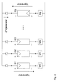
- the proposed structure comprises at least two parallel-associated protection cells, at which their respective photovoltaic generators are connected.
- the protection cell ( Figure 5a ) comprises:
- the device (D) in charge of reducing the voltage of the generator in the event of a reverse connection may be of the diode type, and its anode will be connected to connection point 2 and its cathode to connection point 1.
- the break and/or protection element (M) may be of the fuse, magnetothermal or similar type and must open the circuit corresponding to the cell in the event of experiencing a surge current therethrough.
- Diode (D) withstands the voltage of the generator and is locked (zero current).
- the use of the diode as a voltage reduction element manages to annul the voltage at the terminals of the reverse-connected generator. This allows the break and/or protection device (M 1 -M p ) to be dimensioned for the voltage of the generator.
- FIG. 5b Another preferred embodiment ( Figure 5b ) consists of the same elements of the installation described above but integrates the protection system (M) in the positive pole of the protection cell, which is equivalent to the embodiment described.
Landscapes
- Engineering & Computer Science (AREA)
- Power Engineering (AREA)
- Photovoltaic Devices (AREA)
- Protection Of Static Devices (AREA)
- Emergency Protection Circuit Devices (AREA)
Applications Claiming Priority (1)
| Application Number | Priority Date | Filing Date | Title |
|---|---|---|---|
| ES200801358A ES2345750R (es) | 2008-05-12 | 2008-05-12 | Circuito electrico de proteccion de sistemas fotovoltaicos. |
Publications (3)
| Publication Number | Publication Date |
|---|---|
| EP2120268A2 true EP2120268A2 (de) | 2009-11-18 |
| EP2120268A8 EP2120268A8 (de) | 2010-11-03 |
| EP2120268A3 EP2120268A3 (de) | 2014-08-06 |
Family
ID=41011884
Family Applications (1)
| Application Number | Title | Priority Date | Filing Date |
|---|---|---|---|
| EP09380096.9A Withdrawn EP2120268A3 (de) | 2008-05-12 | 2009-05-07 | Elektrische Schaltung zum Schützen von photovoltaischen Systemen |
Country Status (4)
| Country | Link |
|---|---|
| US (1) | US7969700B2 (de) |
| EP (1) | EP2120268A3 (de) |
| CN (1) | CN101599633A (de) |
| ES (1) | ES2345750R (de) |
Families Citing this family (8)
| Publication number | Priority date | Publication date | Assignee | Title |
|---|---|---|---|---|
| ATE555531T1 (de) * | 2009-08-06 | 2012-05-15 | Sma Solar Technology Ag | Rückstromsensor für parallel geschaltete solarmodule |
| DE102010012294B4 (de) * | 2010-03-23 | 2012-04-26 | Adensis Gmbh | Photovoltaikanlage mit Potentialabsenkung |
| DE102012010083B4 (de) * | 2011-05-23 | 2023-04-27 | Microsemi Corp. | Photovoltaische Sicherheitsabschaltungsvorrichtung |
| US9748769B2 (en) * | 2012-09-21 | 2017-08-29 | Enphase Energy, Inc. | Serially connected micro-inverter system having concertina output voltage control |
| EP2775531A1 (de) * | 2013-03-07 | 2014-09-10 | ABB Oy | Verfahren und Anordnung zum Betrieb eines photovoltaischen Systems und photovoltaisches System |
| US10658833B2 (en) * | 2016-03-23 | 2020-05-19 | Solaredge Technologies Ltd. | Conductor temperature detector |
| DE102017000792B4 (de) * | 2017-01-30 | 2022-08-04 | Mann+Hummel Gmbh | Filterelement, Verfahren zu dessen Herstellung und Luftfilter |
| CN106877816B (zh) * | 2017-03-31 | 2019-09-10 | 阳光电源(上海)有限公司 | 一种光伏组串反接检测方法及装置 |
Family Cites Families (12)
| Publication number | Priority date | Publication date | Assignee | Title |
|---|---|---|---|---|
| JPH06334208A (ja) * | 1993-05-19 | 1994-12-02 | Nec Corp | 太陽発電装置 |
| JPH07177652A (ja) * | 1993-12-17 | 1995-07-14 | Canon Inc | 太陽光発電システムおよび太陽光発電システムの保護方式 |
| JP3406124B2 (ja) * | 1995-07-05 | 2003-05-12 | 関西電力株式会社 | 融雪機能を有する太陽光発電システム |
| JPH09182279A (ja) * | 1995-10-26 | 1997-07-11 | Nitto Kogyo Kk | 太陽光発電システムにおける短絡検出装置 |
| JP2001068706A (ja) * | 1999-08-25 | 2001-03-16 | Sanyo Electric Co Ltd | 太陽電池装置 |
| US6593520B2 (en) * | 2000-02-29 | 2003-07-15 | Canon Kabushiki Kaisha | Solar power generation apparatus and control method therefor |
| WO2003036688A2 (en) * | 2001-10-25 | 2003-05-01 | Sandia Corporation | Alternating current photovoltaic building block |
| US8212138B2 (en) * | 2003-05-16 | 2012-07-03 | The United States Of America As Represented By The Administrator Of National Aeronautics And Space Administration | Reverse bias protected solar array with integrated bypass battery |
| JP2005175370A (ja) * | 2003-12-15 | 2005-06-30 | Oonanba Kk | 太陽電池パネル用端子ボックス |
| EP1946418A2 (de) * | 2005-10-24 | 2008-07-23 | Conergy AG | Schalter-sicherung mit steuerverwaltung für solarzellen |
| DE202006007613U1 (de) * | 2006-05-11 | 2006-08-17 | Beck, Manfred | Fotovoltaikanlage und Brandschutzsicherung hierfür |
| US20090272420A1 (en) * | 2007-10-18 | 2009-11-05 | Searete Llc | Method and system for converting light to electric power |
-
2008
- 2008-05-12 ES ES200801358A patent/ES2345750R/es active Pending
-
2009
- 2009-05-07 EP EP09380096.9A patent/EP2120268A3/de not_active Withdrawn
- 2009-05-12 US US12/453,474 patent/US7969700B2/en not_active Expired - Fee Related
- 2009-05-12 CN CNA2009101419488A patent/CN101599633A/zh active Pending
Also Published As
| Publication number | Publication date |
|---|---|
| US7969700B2 (en) | 2011-06-28 |
| EP2120268A8 (de) | 2010-11-03 |
| CN101599633A (zh) | 2009-12-09 |
| ES2345750A2 (es) | 2010-09-30 |
| US20090279221A1 (en) | 2009-11-12 |
| ES2345750R (es) | 2010-10-13 |
| EP2120268A3 (de) | 2014-08-06 |
Similar Documents
| Publication | Publication Date | Title |
|---|---|---|
| US7969700B2 (en) | Electrical circuit for protecting photovoltaic systems | |
| EP3017520B1 (de) | Solarzellenanordnung | |
| JP6299028B2 (ja) | 光起電ストリングの開放電圧を制限する回路および方法 | |
| EP4404406B1 (de) | Schutzvorrichtung und schutzverfahren für ein fotovoltaisches stromerzeugungssystem und fotovoltaisches stromerzeugungssystem | |
| US12548997B2 (en) | Photovoltaic power generation system, photovoltaic inverter, and direct current combiner box | |
| EP3442116B1 (de) | Anlage zum betreiben von hilfsaggregaten in energieerzeugungsanlagen | |
| US20130221755A1 (en) | Circuit Arrangement for Setting a Potential of a Photovoltaic Generator | |
| CN205509468U (zh) | 汇流箱保护装置 | |
| US8729444B2 (en) | Photovoltaic system with potential reduction | |
| KR20170078547A (ko) | 태양광 발전장치용 안전 접속반 | |
| KR102853630B1 (ko) | 지락 차단에 강인한 태양광 발전 시스템 | |
| US20140217832A1 (en) | Disconnect switches in dc power systems | |
| Zhao et al. | Hybrid DC switch for solar array fault protection | |
| JPH10285965A (ja) | 太陽光発電システム | |
| CN203660567U (zh) | 光伏系统及用于光伏系统的逆变器 | |
| CN220605544U (zh) | 光伏发电系统、光伏逆变器及直流汇流箱 | |
| KR20200130532A (ko) | 아크 및 역전류를 차단하고 온도유지가 가능한 태양광 모듈용 접속함 | |
| CN103595014A (zh) | 一种光伏发电系统保护装置 | |
| KR100871167B1 (ko) | 쏠라셀 보호회로가 구비된 커넥터 | |
| CN117220239A (zh) | 一种光伏发电系统、光伏逆变器及直流汇流箱 | |
| CN106936112A (zh) | 汇流箱保护装置 | |
| HK40006926A (en) | Installation for powering auxiliary equipment in electrical energy generation plants | |
| KR20170078548A (ko) | 태양광 발전장치용 접속반 |
Legal Events
| Date | Code | Title | Description |
|---|---|---|---|
| PUAI | Public reference made under article 153(3) epc to a published international application that has entered the european phase |
Free format text: ORIGINAL CODE: 0009012 |
|
| AK | Designated contracting states |
Kind code of ref document: A2 Designated state(s): AT BE BG CH CY CZ DE DK EE ES FI FR GB GR HR HU IE IS IT LI LT LU LV MC MK MT NL NO PL PT RO SE SI SK TR |
|
| RIN1 | Information on inventor provided before grant (corrected) |
Inventor name: MUGUERZA OLCOZ, LUIS Inventor name: BALDA BELZUNEGUI, JULIAN Inventor name: COLOMA CALAHORRA, JAVIER |
|
| RAP1 | Party data changed (applicant data changed or rights of an application transferred) |
Owner name: INGETEAM POWER TECHNOLOGY, S.A. |
|
| PUAL | Search report despatched |
Free format text: ORIGINAL CODE: 0009013 |
|
| AK | Designated contracting states |
Kind code of ref document: A3 Designated state(s): AT BE BG CH CY CZ DE DK EE ES FI FR GB GR HR HU IE IS IT LI LT LU LV MC MK MT NL NO PL PT RO SE SI SK TR |
|
| AX | Request for extension of the european patent |
Extension state: AL BA RS |
|
| RIC1 | Information provided on ipc code assigned before grant |
Ipc: H01L 31/04 20140101AFI20140701BHEP Ipc: H02H 7/00 20060101ALI20140701BHEP |
|
| STAA | Information on the status of an ep patent application or granted ep patent |
Free format text: STATUS: THE APPLICATION IS DEEMED TO BE WITHDRAWN |
|
| 18D | Application deemed to be withdrawn |
Effective date: 20150207 |