EP2120704B1 - Contraste d'image mr par ultrason - Google Patents
Contraste d'image mr par ultrason Download PDFInfo
- Publication number
- EP2120704B1 EP2120704B1 EP07856185A EP07856185A EP2120704B1 EP 2120704 B1 EP2120704 B1 EP 2120704B1 EP 07856185 A EP07856185 A EP 07856185A EP 07856185 A EP07856185 A EP 07856185A EP 2120704 B1 EP2120704 B1 EP 2120704B1
- Authority
- EP
- European Patent Office
- Prior art keywords
- ultrasound
- magnetic resonance
- pulse
- image
- frequency
- Prior art date
- Legal status (The legal status is an assumption and is not a legal conclusion. Google has not performed a legal analysis and makes no representation as to the accuracy of the status listed.)
- Not-in-force
Links
Images


Classifications
-
- G—PHYSICS
- G01—MEASURING; TESTING
- G01R—MEASURING ELECTRIC VARIABLES; MEASURING MAGNETIC VARIABLES
- G01R33/00—Arrangements or instruments for measuring magnetic variables
- G01R33/20—Arrangements or instruments for measuring magnetic variables involving magnetic resonance
- G01R33/44—Arrangements or instruments for measuring magnetic variables involving magnetic resonance using nuclear magnetic resonance [NMR]
- G01R33/48—NMR imaging systems
- G01R33/4808—Multimodal MR, e.g. MR combined with positron emission tomography [PET], MR combined with ultrasound or MR combined with computed tomography [CT]
- G01R33/4814—MR combined with ultrasound
-
- G—PHYSICS
- G01—MEASURING; TESTING
- G01R—MEASURING ELECTRIC VARIABLES; MEASURING MAGNETIC VARIABLES
- G01R33/00—Arrangements or instruments for measuring magnetic variables
- G01R33/20—Arrangements or instruments for measuring magnetic variables involving magnetic resonance
- G01R33/44—Arrangements or instruments for measuring magnetic variables involving magnetic resonance using nuclear magnetic resonance [NMR]
- G01R33/48—NMR imaging systems
- G01R33/54—Signal processing systems, e.g. using pulse sequences ; Generation or control of pulse sequences; Operator console
- G01R33/56—Image enhancement or correction, e.g. subtraction or averaging techniques, e.g. improvement of signal-to-noise ratio and resolution
- G01R33/563—Image enhancement or correction, e.g. subtraction or averaging techniques, e.g. improvement of signal-to-noise ratio and resolution of moving material, e.g. flow contrast angiography
- G01R33/56358—Elastography
-
- A—HUMAN NECESSITIES
- A61—MEDICAL OR VETERINARY SCIENCE; HYGIENE
- A61B—DIAGNOSIS; SURGERY; IDENTIFICATION
- A61B5/00—Measuring for diagnostic purposes; Identification of persons
- A61B5/0033—Features or image-related aspects of imaging apparatus, e.g. for MRI, optical tomography or impedance tomography apparatus; Arrangements of imaging apparatus in a room
- A61B5/0035—Features or image-related aspects of imaging apparatus, e.g. for MRI, optical tomography or impedance tomography apparatus; Arrangements of imaging apparatus in a room adapted for acquisition of images from more than one imaging mode, e.g. combining MRI and optical tomography
-
- A—HUMAN NECESSITIES
- A61—MEDICAL OR VETERINARY SCIENCE; HYGIENE
- A61B—DIAGNOSIS; SURGERY; IDENTIFICATION
- A61B8/00—Diagnosis using ultrasonic, sonic or infrasonic waves
Definitions
- the invention is directed to a method for generating a contrast-giving effect in the image representation of a magnetic resonance tomography method and / or system in which soft matter is exposed to the influence of a high-frequency pulse field of a magnetic resonance tomography system and ultrasound signals are pulsed coupled into the high-frequency pulse field and irradiated. Furthermore, the invention is directed to the use of a magnetic resonance tomography system. Furthermore, the invention is directed to a device comprising an ultrasound emitter and a magnetic resonance tomography system with such a device.
- NMR Nuclear Magnetic Resonance
- the NMR utilizes the effect that the nuclear spins of a medium or a material in an external magnetic field align themselves to a somewhat larger proportion parallel to this magnetic field than in antiparallel to it.
- HF high-frequency
- FID Free Induction Decay or Hahn Echo
- T 1 tissue-specific variable involved in the imaging of these MRI / MRI imaging techniques
- T 2 spin-spin relocation
- NAR Nuclear Acoustic Resonance
- Another application of the combination of magnetic resonance and ultrasound is according to the WO 01/43640 A2 It is to combine the present in a magnetic resonance tomography both for an MRI method and for an ultrasound method transmitting, receiving and evaluation units together that in the visual representation of the magnetic resonance tomograph both the processed NMR signals and the processed ultrasound Signals are visualized. Also in this case, a mutual influence of the signals or an influence on the image quality is not apparent.
- the invention is the object of the invention to provide a solution that allows influencing the contrast of the image representation of an imaging MRI method.
- this object is achieved in that an ultrasound signal pulse sequence is coupled to and irradiated into an image pulse sequence or sequence generated by the magnetic resonance tomography system such that the movement of the soft matter induced by ultrasound radiation pressure can be represented as an image contrast in the image representation of the magnetic resonance tomography system and / or displayed.
- the invention is therefore based on the knowledge that coupling of the sound to the nuclear spin system is possible by means of pulsed ultrasound and this in superimposition with and influencing the high-frequency pulses of the magnetic resonance tomograph or an NMR system to a modified by the ultrasound irradiation modified image representation of the imaging MR or MRI procedure.
- a high-frequency pulse field is not influencing Ultrasonic wave shown, but it is made an active influence of the exposed in the magnetic field to a high-frequency pulse examined material or matter and then made visible directly in the image display of the MRI. This influence is due to the signal being attenuated by the dynamics introduced by the ultrasound radiation.
- the NMR method or the magnetic resonance tomography method now allows increased recording frequencies thanks to ultrasound. This not only leads to shorter recording times, but also to a better temporal resolution, which in the investigated matter under the influence of the NMR occurring processes in the image representation. It is now the visualization of the induced movement of matter by ultrasonic radiation possible. This leads to contrast representations in the image, which then clearly differentiate ultrasound sonicated areas of matter from non-ultrasonically sonicated areas of matter or make them distinguishable. Due to the ultrasound radiation, a collective movement due to a viscous momentum transfer is introduced into the material or medium exposed to the magnetic resonance tomography, wherein the viscosity of the respective soft matter or liquid greatly influences the range and nature of the ultrasound influence.
- the invention consists in the visualization of the viscous momentum transfer or sound path or ultrasound radiation pressure in a soft matter by coupling a, in particular shielded, ultrasound emitter in the high-frequency field of a magnetic resonance tomograph while adjusting or at least taking into account the motion sensitivity of the tomograph image or its image sequences.
- the invention therefore provides that the sound path and / or the ultrasound radiation pressure and / or a sound-induced momentum transfer in the soft matter is displayed.
- Particularly useful can be used to image the directional motion diffusion sensitive sequences, so that the invention also provides that the sequences of the radio-frequency pulses are diffusion-sensitive sequences.
- the image pulse sequence or sequence (echo sequence) to another bipolar Field gradient in particular between the 90 ° and the 180 ° pulse is extended.
- the contrast-giving effect can be achieved particularly advantageously by selecting the propagation direction of the ultrasound parallel to the diffusion-sensitive gradient, which the invention likewise provides in a further embodiment.
- a gradient preferably a gradient in the direction of the main magnetic field B 0
- a layer is selected and in the selected layer in the remaining directions, preferably in the y- and x-direction, over the phase and the Frequency is a point selection is performed, wherein the ultrasonic pulse is irradiated respectively after the slice selection, which the invention also provides.
- the invention further provides for a shielded ultrasound emitter and / or transmitter to be arranged within the central opening of a magnetic resonance tomograph and coupled into its high-frequency pulse field.
- ultrasound is coupled in via a waveguide into the radiofrequency pulse field of the magnetic resonance tomography system.
- the coupling can be achieved in a particularly favorable manner in that the ultrasound emitter and / or transmitter is coupled in a synchronized manner to the radiofrequency pulse field by means of a radio-frequency antenna.
- the high-frequency pulse signal of the magnetic resonance tomograph is detected with the high-frequency antenna and used for the targeted irradiation of the ultrasonic pulse.
- a control signal of the magnetic resonance tomography system is used.
- a particularly favorable for medical examination positioning of the ultrasound source is given when the ultrasound emitter and / or transmitter is arranged in the region of a radio-frequency coil within the magnetic resonance tomograph or the ultrasound is transported by means of a waveguide in this area.
- the radio-frequency coil is in particular that which is used to transmit the radio-frequency pulses.
- the above object is further achieved by the use of a magnetic resonance tomography system by introducing a shielded ultrasound emitter into the central opening of a magnetic resonance tomograph and coupling the ultrasound emitter into the radiofrequency pulse field of the magnetic resonance tomograph and timed irradiation of ultrasound pulses into the radiofrequency pulse field generated by the magnetic resonance tomography system to produce a high-contrast representation which generated in a soft matter introduced into the examination field of the tomograph induced by ultrasonic radiation movement of matter in the image representation of the magnetic resonance tomography system.
- a device comprising an electromagnetically shielded ultrasound emitter with means for detecting a radiofrequency pulse field used by a magnetic resonance tomograph in operative connection with the ultrasound emitter and with means for synchronized irradiation of ultrasound pulse sequences in its image pulse sequence or sequence.
- This apparatus can be installed easily into any scanner. No intervention, neither in the hardware nor in the software of the magnetic resonance tomograph, is necessary.
- the temporal synchronization takes place via an antenna signal received by an antenna of the device, which captures the high-frequency stray field outside the tomograph.
- the necessary timing of the pulses and the ultrasound pulse generation takes place in a separate electronics, wherein the only connection on the ultrasound head in the tomograph is a non-magnetic coaxial cable.
- the invention also provides a magnetic resonance tomography system which includes a device according to claim 14 and means for displaying a directed movement induced by ultrasound radiation pressure in a volume element of soft matter exposed to the radio-frequency pulse field in the magnetic resonance tomograph of the magnetic resonance tomography system.
- Soft matter is understood to mean biological material, human or animal tissue, fluid and other non-hard matter that is capable of MRI is.
- Ultrasound is understood to mean frequencies between 2 ⁇ 10 4 to 1 ⁇ 10 9 Hz.
- This pulse part initially points in the direction of the movement and is then divided over subsequent impacts in all directions.
- a directional motion is created whose velocity increases with the number of oscillations until it equilibrates with the frictional force.
- the frictional force in liquids is directly proportional to the product of speed and viscosity.
- Another reason for a flow movement is that the compression by the expanding sound waveguide (the respective medium, in in the case of the soft matter of the present invention) has a predetermined direction, while the decompression takes place from all directions due to contraction of the respective medium (soft matter).
- this movement only relates to the volume directly affected by the stroke (a few nm) on the sound conductor and does not affect the more distant areas.
- T * 2 time shows no strong frequency dependence. Influence strength scales with the ultrasound energy introduced into the system and is related to viscosity. Ultrasound triggers a process that persists for a period of time beyond the duration of the ultrasound pulse. There is a collective movement in the sample of soft matter in the micrometer range, in contrast to the only nanometer large sound deflections. This was spatially resolved in a 1.5 T (Tesla) nuclear magnetic resonance tomograph or magnetic resonance tomograph as used in medicine. examined. The terms magnetic resonance tomograph and magnetic resonance tomograph are synonyms.
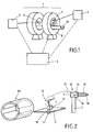
- the magnetic resonance imaging system used essentially comprises a three-part construction, from a standard 1.5T nuclear magnetic resonance tomograph, which is described in US Pat FIG. 1 schematically shown and provided with the reference numeral 1, an ultrasonic emitter and / or transmitter 2 with its control electronics 3 and a coupling element 4, in the present case a high frequency (RF) - antenna, with connected circuit 5 for coupling and coupling of the ultrasonic emitter
- the system and the method are controlled by control units and elements 6 comprising radio-frequency or radio-frequency generators and amplifiers.
- the ultrasonic transmitter 2 used is dimensioned such that not only the waveguide 7 but also the emitter formed as a piezoceramic 9, and thus the ultrasound transmitter and emitter 2 as a whole or as a unit, can be incorporated into the transmitting and receiving coil 8 of the magnetic resonance tomograph 1 , like from the FIG. 1 is apparent. But it is also possible to conduct the sound from the outside via suitable waveguide to the medium, which is not realized in the present embodiment, however ..
- the transmitting and receiving coil 8 is eg a saddle coil, as in the medical application of a magnetic resonance tomograph 1 for Recordings on the patient's head is used.
- FIG. 2 The schematic structure for the measurements with ultrasound on a magnetic resonance tomograph 1 is in FIG. 2 shown schematically.
- the FIG. 2 shows in the left part of a saddle coil 8a (head coil), in the middle part of a base plate 9 with a bore 10 for the sample container 11th and a tripod 12 as a holder for the ultrasonic head 13 and the ultrasonic transmitter and emitter 2.
- the base plate 9, the sample container 11 and the stand 12 are made entirely of Teflon, since this brings only low electrical losses with it no protons in the structure of this Arrangement, so that this arrangement for the magnetic resonance imaging 1 "invisible".
- the saddle coil has a dimension of about 20 x 20 cm, to which the base plate 9 is adapted with its side length of 20 cm.
- the very thin, round 9.45 MHz piezoceramic 14 has a diameter of about 5 mm and is glued within the housing 15 on a 2 mm thick inner wall surface and on the coaxial on the opposite wall surface of the housing 15 outside glued waveguide 7 made of quartz coupled.
- the formed as a quartz rod waveguide 7 has a diameter of 5 mm and a length of 40 mm.
- the housing 15 is made entirely of a Cu-Al alloy metal so as to form an electromagnetic radio frequency (RF) shield for the piezoceramic 14.
- the base of the cuboid housing 15 is 10 x 10 mm.
- This construction brings two decisive advantages.
- the piezoceramic 14 is electromagnetically isolated from the NMR resonant circuit and also can be very good heat dissipated due to the contact to the aluminum housing 15. This allows for higher performance during operation.
- the losses in the sound intensity at the ceramic-aluminum and aluminum-quartz junctions are very small, on the one hand, because the impedance differences between ceramic-aluminum and aluminum-quartz are small, and, on the other hand, the adhesive layers are thin compared to the wavelength, thus providing good transmission is guaranteed.
- Another sensitive site for electromagnetic leaks at Transmitter is the supply line 18. This is guided within the aluminum tube 17 to the transmitter and is thus "invisible" for the NMR resonant circuit.
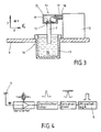
- the base plate 9 In the base plate 9 is centrally the bore 10, in which the to be examined and displayed in the image of the magnetic resonance imaging 1 soft matter 16, in this case a water-containing liquid, with the aid of the surrounding cylindrical sample container of Teflon 11 is introduced, as this from the enlarged and schematic sectional view of FIG. 3 is apparent.
- the stand 12 made of Teflon is mounted on the base plate 9 and connected via a likewise made of a Cu-Al alloy tube 17 which shields an inside running coaxial - connecting cable 18 electromagnetically against high frequency from the outside, with the ultrasonic head 13 , To the connecting cable 18, a high frequency is connected, which is given to the piezoceramic 14 via the connecting cable 18 and a coil 19 for reactive power compensation.
- the base plate 9 provided with the stand 12 and the ultrasonic head 13 is installed centrally in the center of the head coil 8a.
- the head coil 8a with base plate 9, soft material 16 in the sample container 11 and sounder or transducer 13 is - as usual in medical examinations for the patient - driven with the patient stretcher 20 in the center of the MRI scanner 1, where the measurements are performed.
- the control and drive electronics 3 of the ultrasonic transmitter and emitter 2 comprises a trigger unit, a pulse generator, an HF generator and an amplifier.
- the width and the position of the respective ultrasound pulse within the sequence used during the execution of the method according to the invention are set on the trigger unit.
- the Amplitude is generated by means of the generator and the amplifier.
- the frequency generator of the ultrasonic control electronics 3 is externally triggered by a further channel of the trigger unit. In this way, the width of the ultrasound pulse and its position within the respective sequence can be varied as desired.
- the amplitude of the ultrasonic pulse is set on the frequency generator. Since the maximum amplitude in the embodiment is only about 10 V ss to 50 ohms, the signal is amplified by the amplifier to about 40 V ss . but it can also be set or used much higher or higher amplitudes. The amplified signal is then applied to the ultrasound emitter 2 and from there to the waveguide 7.
- the radio-frequency antenna 4 With which the radio-frequency signals (63 MHz at 1.5 T) of the nuclear magnetic resonance tomograph 1 are detected, is additionally fastened on the patient couch 20 outside the tomography magnet.
- the signals detected by the antenna 4 are amplified in a first step with broadband amplifiers. The 90 ° and 180 ° pulses are thus significantly above the noise.
- the high-frequency signals are then largely reduced to their envelope via a rectifier and filter and then converted into a trigger signal with a single-channel discriminator to the pulse logic for the controller 3, 6 of the ultrasound, as shown schematically in FIG FIG. 4 is shown.
- this schematic structure for detecting the high-frequency pulses of the nuclear magnetic resonance tomograph 1 is synchronized with these Coupling and irradiation of the ultrasound in the high-frequency pulse field of the magnetic resonance imaging 1 possible.
- FFT Fast Fourier Transformation
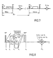
- FIG. 6 shows the location-encoding steps in a cock-echo sequence, where a) encoding in the z-direction b) shows the phase coding of the ⁇ -direction over the field gradient in this direction and thus the definition of the line in the plane; and c) the frequency coding in x-directional mode.
- a field in the plane or the volume element or voxel which takes place by an x-gradient in the selection in this direction.
- the used echo sequence is extended by a further bipolar field gradient between the 90 ° and the 180 ° pulse, as described in US Pat FIG. 8 is shown (standard sequence in tomography). This shows the influence of the movement on the echo under the influence of a bipolar gradient.
- Two volume elements V 1 and V 2 are shown with their phase relative to the environment. The volume element V 1 is stationary and the volume element V 2 moves in the x-direction. Right is in the FIG. 8 the expected echo signal from the two volume elements (voxels) V 1 and V 2 shown qualitatively.
- the further bipolar field gradient causes the protons to have a slightly higher frequency and once a slightly lower frequency depending on the gradient and its location. If the protons are at rest, this fluctuation does nothing in the end. If the protons move, they experience a non-symmetric fluctuation and in this way receive an additional phase, which leads to a reduced signal amplitude in the echo signal, as described in US Pat FIG. 8 is shown for the moving or moving volume element V 2 in the right part of the picture.
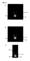
- the following figures 9 to 12 each show images with and without ultrasound irradiation in the imaging sequence or pulse sequence of the magnetic resonance tomograph 1.
- the respective sub-images a), b) and c) each underlying measurements were carried out immediately after one another, without changing the sample ,
- the only difference between the respective underlying measurements a) and b) in each case is merely that one has worked according to the invention with a voltage applied to the ultrasound transmitter and once without the action of ultrasound.
- areas at rest are bright and moving areas are dark.
- the left figure a) shows one when done of the method according to the invention, that is to say using the ultrasound irradiated synchronously in the image sequence of the magnetic resonance tomograph.
- the bipolar field gradient was placed in the direction of the longitudinal axis of the waveguide 7, ie in the sound propagation direction.
- the applied voltage is 50 V ss , which in water (H 2 O) corresponds to a sound pressure of less than 1 bar (measured by the diffraction of visible light at the ultrasonic wave in water).
- the frequency used is 9.45 MHz.
- the nuclear magnetic resonance tomograph 1 measures at a constant magnetic field of 1.5 T, which corresponds to a Lamor frequency of about 63 MHz.
- the gradients are between 5 and 20 mT per meter.
- the image resolution which can be achieved with a gradient in the z-direction of 10-20 mT and an RF pulse length of 1-2 ms, is in the submillimeter range, the motion resolution in the range of ⁇ m.
- the shots of the FIGS. 9 a), 9 b) and 9 c) were obtained with a motion-sensitive NMR sequence.
- the in FIG. 9 a) shown image is an inventive ultrasonic irradiation for 30 ms with an excitation voltage of 40 V ss in the sample basis.
- This channel 21 is in the form of a contrast difference in the representation of the image 9 a) the range of moving soft matter, in this case the moving Water, again.
- the induced movement caused by the irradiated and coupled ultrasound leads to the darker image representation of this area. It is thus the sound path or the ultrasonic radiation pressure or the ultrasound-induced pulse transmission as a contrast difference in the Figure 9 a) made visible and recognizable.
- the channel 21 is formed, which is based on a movement along the applied bipolar gradient is due.
- a gradient in the direction perpendicular to this propagation axis shows no measurable and / or visually presentable and recognizable difference, since no movement is generated in this direction by the irradiated in the high-frequency pulse signal field of the magnetic resonance imaging apparatus 1 ultrasound.
- the Figure 9 b) was recorded without ultrasonic irradiation but under otherwise identical conditions. There is no movement in the brightly displayed liquid 16 and consequently no channel 21.
- the right one Figure 9 c) shows the difference of the gray scale images 9 a) and 9 b) and consequently only the channel 21st
- the FIG. 10 shows representations obtained with a T 2 time sensitive sequence. Also in this case is in the Figure 10 a) to detect a structure 22 under the transducer 13 or below the waveguide 7 when using ultrasound.
- the FIG. 10 shows measurement results obtained with a T 2 weighted sequence in water 16.
- underlying sequence is irradiated ultrasonically synchronized.
- the Figure 10 b) was again recorded without ultrasound and the right Figure 10 c) again shows the difference of the gray value images 10 a) and 10 b).
- FIG. 11 shows images obtained with a T 1 time sensitive sequence.
- a structure 23 is formed, as shown in FIG Figure 11 a) It can be seen that the result of a T 1 - weighted measurement of water (H 2 0) under the influence of ultrasound and the Figure 11 c) the difference of the gray value images 11 a) and 11 b).
- FIGS. 12 a) to 12 c) Again, the influence of the ultrasound and the ability to visualize the thus produced in a soft matter, or in the present case water, viscous momentum transfer in the image representation of a magnetic resonance tomograph 1 in the form of contrast training as a strip 21 or channel 21.
- a glass pane 24 is arranged in the liquid 16, at which the liquid movement or the visualized sound radiation pressure is deflected according to the laws of optics (angle of incidence equal to the angle of reflection).
- the incident on the glass plate 24 Figure 12 a
- the failing FIG. 12b
- the magnetic resonance tomograph 1 can thus be represented in high contrast in the image display of magnetic resonance imaging or magnetic resonance that a collective motion is introduced into the sample of soft matter 16 by the ultrasound and a sound-induced viscous momentum transfer between the matter particles is triggered. It is the sound path in the soft matter or liquid or the ultrasonic radiation pressure in the signal field of the Magnetic resonance tomography or nuclear spin tomography - system on the one hand and the ultrasonic signal field on the other hand, soft matter 16 shown in high contrast. Spatially resolved measurements on different viscous fluids further confirm that the viscosity changes the range and nature of the ultrasound influence. In addition, measurements with measuring sequences (T 1 , T 2 -weighted) used in medicine show a structure 22, 23 caused by the ultrasound. Thus, the spectrum of the contrast possibilities, for example, around the image, can be determined by targeted irradiation of ultrasound during an NMR measurement Parameter viscosity be extended.
- the method found can be used for diagnosis in human medical examinations, since the energy introduced into a medium (soft matter) in the method according to the invention is far below the permitted limits.
- the pressure amplitude P is about 1 bar, which is safe from today's state.
- the principle of the combination of ultrasound and NMR can be implemented.
- NMR nuclear magnetic resonance
- Ultrasound (frequency between 2 x 10 4 to 1 x 10 9 Hz) is the appropriate tool. At frequencies in the megahertz range, the wavelength for sound in liquids is in the range of a few tenths of a millimeter and can thus be used very specifically for local manipulation. Another positive feature is the compatibility of ultrasound for human and animal cells, as long as the acting power is kept low.
- the difference between the magnetizations or the signal amplitudes between measurements with and without sound contain a measure of the strength of the ultrasonic influence. In this case, for the cases of equilibrium and imbalance, an influence of the ultrasound in the total nuclear magnetization of a specimen can be found again.
- Longitudinal sound is a pressure fluctuation that spreads spatially in a medium.
- the time course at a point in space provides the characteristic of the sound or a sound wave sizes. These are the motion amplitude, the velocity amplitude, the pressure amplitude, the sound velocity, the sound characteristic impedance, the sound attenuation that indicates which distance the pressure amplitude has dropped due to the release of energy to an e-tel, and the sound radiation pressure, which is the overpressure prevailing on average in a medium through which a sound wave passes.
- each pressure fluctuation can be assigned a frequency spectrum over its time course. Any pressure fluctuation can be represented by a superposition of amplitude-modulated periodic oscillations.
- the laws of wave mechanics can be applied to the propagation of sound, which is why sound waves are used. Piezo ceramics are particularly suitable for generating sound waves.
- the nucleons are no longer in a fixed location.
- the position of a nucleon can only be described statistically, so that in such media or matter a superposition of the individual nucleon motion and the density fluctuation moving through the respective medium are considered.
- the influence of ultrasound on the nuclear spin ensemble is on the one hand in the local pressure change and on the other hand in a collective movement introduced into the medium / soft matter.
- the pressure difference influences the average shock frequency and the distances between the nuclei.
- the relaxation times T 1 and T 2 are influenced.
- the collective movement leads to a change of position in the sample or in the magnetic field, which influences the T * 2 time analogous to the diffusion, if there are magnetic field inhomogeneities.
- the movement in the irradiated medium is caused by the attenuation at which it is comes to a particular viscous momentum transfer. This leads to a movement along the propagation direction of the sound wave.
- the range of the collective motion depends on the viscosity of the fluid. At very high viscosity, the high number of bursts causes the transmitted pulse to diffuse more quickly than the lower viscosity, where the pulse retains its direction for longer.
- the application of ultrasound influences the nuclear spin ensemble and the magnetization of the respective soft matter.
- the ultrasound influence should be maximum if the frequency of the irradiated ultrasound coincides exactly with the Lamor frequency.
- a measurement sequence with which the entire influence of the ultrasound on the magnetization can be determined and determined is the Hahn-Echo sequence.
- the influence on the dephasing speed is reflected in the line shape of the frequency spectrum, while the influence on relaxation times T 2 and T 1 is combined in the signal amplitude.
- the time for the ultrasound to come in is between the 90 ° and 180 ° pulses. Whether the ultrasound is irradiated before or after the 180 ° pulse makes no difference. Unfavorable would be an irradiation symmetric about the 180 ° pulse, as could possibly cancel effects by the inversion pulse.
- the echo is recorded via the Hahn-Echo sequence.
- the ultrasound is radiated between the 90 ° and the 180 ° pulse.
- the ultrasound is irradiated for example 5 ms after the 90 ° pulse and the sample body or sample container 11 is exposed to the mechanical vibrations.
- the Excitation voltage at the piezoelectric core 14 is for example 40 V ss and the operating time of the transmitter is for example 50 ms.
Landscapes
- Physics & Mathematics (AREA)
- Nuclear Medicine, Radiotherapy & Molecular Imaging (AREA)
- Health & Medical Sciences (AREA)
- Condensed Matter Physics & Semiconductors (AREA)
- Radiology & Medical Imaging (AREA)
- Engineering & Computer Science (AREA)
- General Health & Medical Sciences (AREA)
- High Energy & Nuclear Physics (AREA)
- General Physics & Mathematics (AREA)
- Pulmonology (AREA)
- Theoretical Computer Science (AREA)
- Signal Processing (AREA)
- Vascular Medicine (AREA)
- Magnetic Resonance Imaging Apparatus (AREA)
- Ultra Sonic Daignosis Equipment (AREA)
Claims (14)
- Procédé de production d'un effet formant contraste dans la représentation de l'image d'un procédé et/ou d'un système de tomographie par résonance magnétique, dans lequel une matière douce (16) est exposée à l'influence d'un champ d'impulsions haute fréquence d'une installation de tomographie par résonance magnétique, et des signaux ultrasons sont injectés et envoyés de manière pulsée dans le champ de signaux d'impulsions haute fréquence,
caractérisé en ce que
une séquence d'impulsions de signaux ultrasons est injectée, et envoyée de manière synchronisée, dans une suite ou une séquence d'impulsions d'images produite par l'installation de tomographie par résonance magnétique, de telle sorte que, dans la représentation de l'image de l'installation de tomographie par résonance magnétique, le mouvement de la matière douce (16), induit par la pression du rayonnement ultrason, soit représentable et/ou représenté en tant que contraste d'image (21). - Procédé selon la revendication 1, caractérisé en ce que les séquences des impulsions haute fréquence sont des séquences sensibles à la diffusion.
- Procédé selon l'une des revendications précédentes, caractérisé en ce que la suite ou la séquence d'impulsions d'images est une séquence d'échos de Hahn, qui est élargie d'un gradient de champ bipolaire, en particulier d'entre l'impulsion 90° et l'impulsion 180°.
- Procédé selon l'une des revendications précédentes, caractérisé en ce que la direction de propagation des ultrasons est choisie parallèle au gradient sensible à la diffusion.
- Procédé selon l'une des revendications précédentes, caractérisé en ce que, le long d'un gradient, de préférence d'un gradient dans la direction du champ magnétique principal B0, une couche est sélectionnée, et une sélection de points est mise en oeuvre dans la couche sélectionnée, dans les directions restantes, de préférence dans les directions y et x, via la phase et la fréquence, dans lequel l'impulsion ultrason est respectivement envoyée après la sélection de la couche.
- Procédé selon l'une des revendications précédentes, caractérisé en ce que sont injectés et envoyés des ultrasons avec une fréquence comprise entre 2 et 30 MHz et avec une longueur d'impulsion comprise entre 1 et 50 ms et avec une pression acoustique ≤ 1 bar.
- Procédé selon l'une des revendications précédentes, caractérisé en ce qu'un émetteur d'ultrasons blindé (2) et/ou un transmetteur d'ultrasons est agencé à l'intérieur de l'ouverture centrale d'un tomographe par résonance magnétique (1), et est injecté dans le champ d'impulsions haute fréquence de ce dernier.
- Procédé selon l'une des revendications précédentes, caractérisé en ce que les ultrasons sont injectés, via un guide d'ondes (7), dans le champ d'impulsions haute fréquence de l'installation de tomographie par résonance magnétique.
- Procédé selon l'une des revendications précédentes, caractérisé en ce que l'émetteur d'ultrasons (2) et/ou le transmetteur d'ultrasons sont couplés avec le champ d'impulsions haute fréquence, de manière synchronisée et via une antenne HF (4).
- Procédé selon la revendication 9, caractérisé en ce que, à l'aide de l'antenne HF (4), le signal d'impulsions HF du tomographe par résonance magnétique (1) est détecté et utilisé pour l'envoi ciblé de l'impulsion ultrason.
- Procédé selon l'une des revendications précédentes, caractérisé en ce que, pour le positionnement temporel des ultrasons dans la séquence de représentation de l'image, on utilise un signal de commande de l'installation de tomographie par résonance magnétique.
- Procédé selon l'une des revendications précédentes, caractérisé en ce que l'émetteur d'ultrasons (2) et/ou le transmetteur d'ultrasons est agencé dans la zone d'une bobine haute fréquence (8a) à l'intérieur du tomographe par résonance magnétique (1), ou les ultrasons sont transportés dans cette zone au moyen d'un guide d'ondes.
- Utilisation d'une installation de tomographie par résonance magnétique, par introduction d'un émetteur d'ultrasons blindé (2) dans l'ouverture centrale d'un tomographe par résonance magnétique (1) et injection de l'émetteur d'ultrasons (2) dans le champ d'impulsions haute fréquence du tomographe par résonance magnétique (1), ainsi que par envoi, de manière définie dans le temps, d'impulsions ultrasons dans le champ d'impulsions haute fréquence produit par l'installation de tomographie par résonance magnétique, pour produire une représentation à fort contraste du mouvement de la matière (16) dans la représentation de l'image de l'installation de tomographie par résonance magnétique, lequel mouvement est produit dans une matière douce (16) introduit dans le champ d'examen du tomographe par résonance magnétique (1) et induit par la pression du rayonnement ultrason.
- Installation de tomographie par résonance magnétique comprenant un émetteur ultrason blindé (2), avec des moyens pour la détection d'un champ, utilisé pour former une image, d'impulsions haute fréquence d'un tomographe par résonance magnétique (1) situé en liaison fonctionnelle avec l'émetteur d'ultrasons (2), et avec des moyens pour un envoi synchronisé de séquences d'impulsions ultrasons dans sa suite ou sa séquence d'impulsions d'images, ainsi que des moyens pour représenter un mouvement orienté, induit par la pression de rayonnement ultrason, dans un élément de volume exposé, dans le tomographe par résonance magnétique (1) de l'installation de tomographie par résonance magnétique, au champ d'impulsions haute fréquence, cet élément étant constitué d'une matière douce (16).
Applications Claiming Priority (2)
| Application Number | Priority Date | Filing Date | Title |
|---|---|---|---|
| DE102006058264A DE102006058264A1 (de) | 2006-12-08 | 2006-12-08 | MR-Bildkontrast mittels Ultraschall |
| PCT/EP2007/010002 WO2008067905A1 (fr) | 2006-12-08 | 2007-11-20 | Contraste d'image mr par ultrason |
Publications (2)
| Publication Number | Publication Date |
|---|---|
| EP2120704A1 EP2120704A1 (fr) | 2009-11-25 |
| EP2120704B1 true EP2120704B1 (fr) | 2013-01-16 |
Family
ID=39283925
Family Applications (1)
| Application Number | Title | Priority Date | Filing Date |
|---|---|---|---|
| EP07856185A Not-in-force EP2120704B1 (fr) | 2006-12-08 | 2007-11-20 | Contraste d'image mr par ultrason |
Country Status (3)
| Country | Link |
|---|---|
| EP (1) | EP2120704B1 (fr) |
| DE (1) | DE102006058264A1 (fr) |
| WO (1) | WO2008067905A1 (fr) |
Families Citing this family (1)
| Publication number | Priority date | Publication date | Assignee | Title |
|---|---|---|---|---|
| DE102011085894B4 (de) | 2011-11-08 | 2014-03-27 | Siemens Aktiengesellschaft | Verfahren und elektronische Recheneinrichtung zur Bildgebung und Bildgebungssystem |
Family Cites Families (3)
| Publication number | Priority date | Publication date | Assignee | Title |
|---|---|---|---|---|
| US5307812A (en) * | 1993-03-26 | 1994-05-03 | General Electric Company | Heat surgery system monitored by real-time magnetic resonance profiling |
| US6246895B1 (en) * | 1998-12-18 | 2001-06-12 | Sunnybrook Health Science Centre | Imaging of ultrasonic fields with MRI |
| WO2001043640A2 (fr) * | 1999-12-15 | 2001-06-21 | Koninklijke Philips Electronics N.V. | Systeme d'imagerie diagnostique avec sonde echographique |
-
2006
- 2006-12-08 DE DE102006058264A patent/DE102006058264A1/de not_active Withdrawn
-
2007
- 2007-11-20 WO PCT/EP2007/010002 patent/WO2008067905A1/fr not_active Ceased
- 2007-11-20 EP EP07856185A patent/EP2120704B1/fr not_active Not-in-force
Also Published As
| Publication number | Publication date |
|---|---|
| DE102006058264A1 (de) | 2008-06-12 |
| EP2120704A1 (fr) | 2009-11-25 |
| WO2008067905A1 (fr) | 2008-06-12 |
Similar Documents
| Publication | Publication Date | Title |
|---|---|---|
| DE3937052B4 (de) | Instrumentenkörper für ein medezinisches Instrument zur Untersuchung von Gegenständen wie des menschlichen Körpers | |
| DE69524839T2 (de) | Abbildung der synchronisierten Spinbewegung und der Dehnungswellen mittels magnetischer Resonanz | |
| DE69608181T2 (de) | Verfahren und Gerät für die magnetische Resonanz | |
| DE102009003409B4 (de) | System und Verfahren zur gewebespezifischen MR-Bildgebung von Metaboliten unter Anwendung von spektral-räumlich gebildetem stimulierten Echo | |
| DE3220490A1 (de) | Diagnoseapparat | |
| DE102010013900B4 (de) | Verfahren zur Bildgebung mittels magnetischer Kleinstpartikel sowie Vorrichtung hierfür | |
| DE102012216353B3 (de) | Ansteuerung eines Magnetresonanzsystems zur selektiven Anregung von Teilbereichen | |
| DE19903626A1 (de) | Arterien-Magnetresonanzabbildung mit chemischem Verschiebungsabgleich | |
| EP3378389B1 (fr) | Dispositif de formation d'image sur la base d'une imagerie magnétoscopique et procédé associé | |
| DE102007011807B3 (de) | Sequenz für die Magnet-Resonanz-Bildgebung und Magnet-Resonanz-Gerät hierzu | |
| DE102012205664A1 (de) | Verfahren und Steuervorrichtung zur Ansteuerung eines Magnetresonanzsystems | |
| DE102014213413B4 (de) | Dynamische Felderfassung in einem MRT | |
| DE3908392C2 (fr) | ||
| EP0199202B1 (fr) | Dispositif de résonance de spin nucléaire | |
| DE3539256C2 (de) | Verfahren zur Darstellung der kernmagnetischen Eigenschaften eines zu untersuchenden Objektes | |
| EP2120704B1 (fr) | Contraste d'image mr par ultrason | |
| DE19962847C2 (de) | Magnetresonanz-Bildgebungsverfahren mit Echo-Planar-Bildgebung | |
| DE10219766B4 (de) | Verfahren zur automatischen Vermessung akustischer Resonanzen eines Magnetresonanz-Tomographiegerätes | |
| EP3572824A1 (fr) | Mesure de résonance magnétique insensible à la résistance à l'état bloqué avec un gradient de déphasage | |
| DE19962848A1 (de) | Bildgebungsverfahren | |
| DE102006054599B3 (de) | Verfahren zur selektiven Anregung von Kernspins und Magnet-Resonanz-Gerät | |
| WO2001048501A9 (fr) | Procede de formation d'images par resonance magnetique | |
| DE112020002098T5 (de) | MRT mit Anpassung von Schwingungszuständen | |
| DE19962850B4 (de) | Spektroskopisches Bildgebungsverfahren | |
| DE4103485B4 (de) | Verfahren zur Prüfung von physikalischen und/oder chemischen Eigenschaften von Objekten mittels kernmagnetischer Resonanzspektroskopie |
Legal Events
| Date | Code | Title | Description |
|---|---|---|---|
| PUAI | Public reference made under article 153(3) epc to a published international application that has entered the european phase |
Free format text: ORIGINAL CODE: 0009012 |
|
| 17P | Request for examination filed |
Effective date: 20090706 |
|
| AK | Designated contracting states |
Kind code of ref document: A1 Designated state(s): AT BE BG CH CY CZ DE DK EE ES FI FR GB GR HU IE IS IT LI LT LU LV MC MT NL PL PT RO SE SI SK TR |
|
| DAX | Request for extension of the european patent (deleted) | ||
| 17Q | First examination report despatched |
Effective date: 20100921 |
|
| REG | Reference to a national code |
Ref country code: DE Ref legal event code: R079 Ref document number: 502007011238 Country of ref document: DE Free format text: PREVIOUS MAIN CLASS: A61B0005055000 Ipc: A61B0008000000 |
|
| RIC1 | Information provided on ipc code assigned before grant |
Ipc: A61B 8/00 20060101AFI20120504BHEP Ipc: A61B 5/055 20060101ALI20120504BHEP Ipc: G01R 33/563 20060101ALI20120504BHEP Ipc: G01R 33/48 20060101ALI20120504BHEP |
|
| GRAP | Despatch of communication of intention to grant a patent |
Free format text: ORIGINAL CODE: EPIDOSNIGR1 |
|
| GRAS | Grant fee paid |
Free format text: ORIGINAL CODE: EPIDOSNIGR3 |
|
| GRAA | (expected) grant |
Free format text: ORIGINAL CODE: 0009210 |
|
| AK | Designated contracting states |
Kind code of ref document: B1 Designated state(s): AT BE BG CH CY CZ DE DK EE ES FI FR GB GR HU IE IS IT LI LT LU LV MC MT NL PL PT RO SE SI SK TR |
|
| REG | Reference to a national code |
Ref country code: GB Ref legal event code: FG4D Free format text: NOT ENGLISH |
|
| REG | Reference to a national code |
Ref country code: CH Ref legal event code: EP |
|
| REG | Reference to a national code |
Ref country code: IE Ref legal event code: FG4D Free format text: LANGUAGE OF EP DOCUMENT: GERMAN |
|
| REG | Reference to a national code |
Ref country code: AT Ref legal event code: REF Ref document number: 593425 Country of ref document: AT Kind code of ref document: T Effective date: 20130215 Ref country code: CH Ref legal event code: EP |
|
| REG | Reference to a national code |
Ref country code: DE Ref legal event code: R096 Ref document number: 502007011238 Country of ref document: DE Effective date: 20130314 |
|
| REG | Reference to a national code |
Ref country code: CH Ref legal event code: NV Representative=s name: PATENTANWAELTE SCHAAD, BALASS, MENZL AND PARTN, CH |
|
| REG | Reference to a national code |
Ref country code: NL Ref legal event code: VDEP Effective date: 20130116 |
|
| REG | Reference to a national code |
Ref country code: LT Ref legal event code: MG4D |
|
| PG25 | Lapsed in a contracting state [announced via postgrant information from national office to epo] |
Ref country code: IS Free format text: LAPSE BECAUSE OF FAILURE TO SUBMIT A TRANSLATION OF THE DESCRIPTION OR TO PAY THE FEE WITHIN THE PRESCRIBED TIME-LIMIT Effective date: 20130516 Ref country code: BG Free format text: LAPSE BECAUSE OF FAILURE TO SUBMIT A TRANSLATION OF THE DESCRIPTION OR TO PAY THE FEE WITHIN THE PRESCRIBED TIME-LIMIT Effective date: 20130416 Ref country code: ES Free format text: LAPSE BECAUSE OF FAILURE TO SUBMIT A TRANSLATION OF THE DESCRIPTION OR TO PAY THE FEE WITHIN THE PRESCRIBED TIME-LIMIT Effective date: 20130427 Ref country code: SE Free format text: LAPSE BECAUSE OF FAILURE TO SUBMIT A TRANSLATION OF THE DESCRIPTION OR TO PAY THE FEE WITHIN THE PRESCRIBED TIME-LIMIT Effective date: 20130116 Ref country code: LT Free format text: LAPSE BECAUSE OF FAILURE TO SUBMIT A TRANSLATION OF THE DESCRIPTION OR TO PAY THE FEE WITHIN THE PRESCRIBED TIME-LIMIT Effective date: 20130116 |
|
| PG25 | Lapsed in a contracting state [announced via postgrant information from national office to epo] |
Ref country code: PT Free format text: LAPSE BECAUSE OF FAILURE TO SUBMIT A TRANSLATION OF THE DESCRIPTION OR TO PAY THE FEE WITHIN THE PRESCRIBED TIME-LIMIT Effective date: 20130516 Ref country code: PL Free format text: LAPSE BECAUSE OF FAILURE TO SUBMIT A TRANSLATION OF THE DESCRIPTION OR TO PAY THE FEE WITHIN THE PRESCRIBED TIME-LIMIT Effective date: 20130116 Ref country code: SI Free format text: LAPSE BECAUSE OF FAILURE TO SUBMIT A TRANSLATION OF THE DESCRIPTION OR TO PAY THE FEE WITHIN THE PRESCRIBED TIME-LIMIT Effective date: 20130116 Ref country code: NL Free format text: LAPSE BECAUSE OF FAILURE TO SUBMIT A TRANSLATION OF THE DESCRIPTION OR TO PAY THE FEE WITHIN THE PRESCRIBED TIME-LIMIT Effective date: 20130116 Ref country code: FI Free format text: LAPSE BECAUSE OF FAILURE TO SUBMIT A TRANSLATION OF THE DESCRIPTION OR TO PAY THE FEE WITHIN THE PRESCRIBED TIME-LIMIT Effective date: 20130116 Ref country code: LV Free format text: LAPSE BECAUSE OF FAILURE TO SUBMIT A TRANSLATION OF THE DESCRIPTION OR TO PAY THE FEE WITHIN THE PRESCRIBED TIME-LIMIT Effective date: 20130116 Ref country code: GR Free format text: LAPSE BECAUSE OF FAILURE TO SUBMIT A TRANSLATION OF THE DESCRIPTION OR TO PAY THE FEE WITHIN THE PRESCRIBED TIME-LIMIT Effective date: 20130417 |
|
| PG25 | Lapsed in a contracting state [announced via postgrant information from national office to epo] |
Ref country code: CZ Free format text: LAPSE BECAUSE OF FAILURE TO SUBMIT A TRANSLATION OF THE DESCRIPTION OR TO PAY THE FEE WITHIN THE PRESCRIBED TIME-LIMIT Effective date: 20130116 Ref country code: EE Free format text: LAPSE BECAUSE OF FAILURE TO SUBMIT A TRANSLATION OF THE DESCRIPTION OR TO PAY THE FEE WITHIN THE PRESCRIBED TIME-LIMIT Effective date: 20130116 Ref country code: DK Free format text: LAPSE BECAUSE OF FAILURE TO SUBMIT A TRANSLATION OF THE DESCRIPTION OR TO PAY THE FEE WITHIN THE PRESCRIBED TIME-LIMIT Effective date: 20130116 Ref country code: SK Free format text: LAPSE BECAUSE OF FAILURE TO SUBMIT A TRANSLATION OF THE DESCRIPTION OR TO PAY THE FEE WITHIN THE PRESCRIBED TIME-LIMIT Effective date: 20130116 Ref country code: RO Free format text: LAPSE BECAUSE OF FAILURE TO SUBMIT A TRANSLATION OF THE DESCRIPTION OR TO PAY THE FEE WITHIN THE PRESCRIBED TIME-LIMIT Effective date: 20130116 |
|
| PLBE | No opposition filed within time limit |
Free format text: ORIGINAL CODE: 0009261 |
|
| STAA | Information on the status of an ep patent application or granted ep patent |
Free format text: STATUS: NO OPPOSITION FILED WITHIN TIME LIMIT |
|
| PG25 | Lapsed in a contracting state [announced via postgrant information from national office to epo] |
Ref country code: CY Free format text: LAPSE BECAUSE OF FAILURE TO SUBMIT A TRANSLATION OF THE DESCRIPTION OR TO PAY THE FEE WITHIN THE PRESCRIBED TIME-LIMIT Effective date: 20130116 |
|
| 26N | No opposition filed |
Effective date: 20131017 |
|
| PG25 | Lapsed in a contracting state [announced via postgrant information from national office to epo] |
Ref country code: IT Free format text: LAPSE BECAUSE OF FAILURE TO SUBMIT A TRANSLATION OF THE DESCRIPTION OR TO PAY THE FEE WITHIN THE PRESCRIBED TIME-LIMIT Effective date: 20130116 |
|
| REG | Reference to a national code |
Ref country code: DE Ref legal event code: R097 Ref document number: 502007011238 Country of ref document: DE Effective date: 20131017 |
|
| BERE | Be: lapsed |
Owner name: RHEINISCHE FRIEDRICH-WILHELMS-UNIVERSITAT BONN Effective date: 20131130 |
|
| PG25 | Lapsed in a contracting state [announced via postgrant information from national office to epo] |
Ref country code: MC Free format text: LAPSE BECAUSE OF FAILURE TO SUBMIT A TRANSLATION OF THE DESCRIPTION OR TO PAY THE FEE WITHIN THE PRESCRIBED TIME-LIMIT Effective date: 20130116 |
|
| REG | Reference to a national code |
Ref country code: IE Ref legal event code: MM4A |
|
| PG25 | Lapsed in a contracting state [announced via postgrant information from national office to epo] |
Ref country code: BE Free format text: LAPSE BECAUSE OF NON-PAYMENT OF DUE FEES Effective date: 20131130 |
|
| PG25 | Lapsed in a contracting state [announced via postgrant information from national office to epo] |
Ref country code: IE Free format text: LAPSE BECAUSE OF NON-PAYMENT OF DUE FEES Effective date: 20131120 |
|
| REG | Reference to a national code |
Ref country code: AT Ref legal event code: MM01 Ref document number: 593425 Country of ref document: AT Kind code of ref document: T Effective date: 20131120 |
|
| PG25 | Lapsed in a contracting state [announced via postgrant information from national office to epo] |
Ref country code: AT Free format text: LAPSE BECAUSE OF NON-PAYMENT OF DUE FEES Effective date: 20131120 |
|
| PG25 | Lapsed in a contracting state [announced via postgrant information from national office to epo] |
Ref country code: TR Free format text: LAPSE BECAUSE OF FAILURE TO SUBMIT A TRANSLATION OF THE DESCRIPTION OR TO PAY THE FEE WITHIN THE PRESCRIBED TIME-LIMIT Effective date: 20130116 |
|
| PG25 | Lapsed in a contracting state [announced via postgrant information from national office to epo] |
Ref country code: HU Free format text: LAPSE BECAUSE OF FAILURE TO SUBMIT A TRANSLATION OF THE DESCRIPTION OR TO PAY THE FEE WITHIN THE PRESCRIBED TIME-LIMIT; INVALID AB INITIO Effective date: 20071120 Ref country code: LU Free format text: LAPSE BECAUSE OF NON-PAYMENT OF DUE FEES Effective date: 20131120 |
|
| PG25 | Lapsed in a contracting state [announced via postgrant information from national office to epo] |
Ref country code: MT Free format text: LAPSE BECAUSE OF FAILURE TO SUBMIT A TRANSLATION OF THE DESCRIPTION OR TO PAY THE FEE WITHIN THE PRESCRIBED TIME-LIMIT Effective date: 20130116 |
|
| REG | Reference to a national code |
Ref country code: FR Ref legal event code: PLFP Year of fee payment: 9 |
|
| REG | Reference to a national code |
Ref country code: FR Ref legal event code: PLFP Year of fee payment: 10 |
|
| REG | Reference to a national code |
Ref country code: FR Ref legal event code: PLFP Year of fee payment: 11 |
|
| PGFP | Annual fee paid to national office [announced via postgrant information from national office to epo] |
Ref country code: FR Payment date: 20171124 Year of fee payment: 11 Ref country code: DE Payment date: 20171129 Year of fee payment: 11 |
|
| PGFP | Annual fee paid to national office [announced via postgrant information from national office to epo] |
Ref country code: CH Payment date: 20171124 Year of fee payment: 11 Ref country code: GB Payment date: 20171124 Year of fee payment: 11 |
|
| REG | Reference to a national code |
Ref country code: DE Ref legal event code: R119 Ref document number: 502007011238 Country of ref document: DE |
|
| REG | Reference to a national code |
Ref country code: CH Ref legal event code: PL |
|
| GBPC | Gb: european patent ceased through non-payment of renewal fee |
Effective date: 20181120 |
|
| PG25 | Lapsed in a contracting state [announced via postgrant information from national office to epo] |
Ref country code: CH Free format text: LAPSE BECAUSE OF NON-PAYMENT OF DUE FEES Effective date: 20181130 Ref country code: LI Free format text: LAPSE BECAUSE OF NON-PAYMENT OF DUE FEES Effective date: 20181130 |
|
| PG25 | Lapsed in a contracting state [announced via postgrant information from national office to epo] |
Ref country code: DE Free format text: LAPSE BECAUSE OF NON-PAYMENT OF DUE FEES Effective date: 20190601 Ref country code: FR Free format text: LAPSE BECAUSE OF NON-PAYMENT OF DUE FEES Effective date: 20181130 |
|
| PG25 | Lapsed in a contracting state [announced via postgrant information from national office to epo] |
Ref country code: GB Free format text: LAPSE BECAUSE OF NON-PAYMENT OF DUE FEES Effective date: 20181120 |