EP2121502B1 - Système de déplacement et de stabilisation d'une base mobile - Google Patents
Système de déplacement et de stabilisation d'une base mobile Download PDFInfo
- Publication number
- EP2121502B1 EP2121502B1 EP08719211.8A EP08719211A EP2121502B1 EP 2121502 B1 EP2121502 B1 EP 2121502B1 EP 08719211 A EP08719211 A EP 08719211A EP 2121502 B1 EP2121502 B1 EP 2121502B1
- Authority
- EP
- European Patent Office
- Prior art keywords
- mobile base
- profile
- mobile
- monorail
- segment
- Prior art date
- Legal status (The legal status is an assumption and is not a legal conclusion. Google has not performed a legal analysis and makes no representation as to the accuracy of the status listed.)
- Ceased
Links
Images

Classifications
-
- B—PERFORMING OPERATIONS; TRANSPORTING
- B66—HOISTING; LIFTING; HAULING
- B66F—HOISTING, LIFTING, HAULING OR PUSHING, NOT OTHERWISE PROVIDED FOR, e.g. DEVICES WHICH APPLY A LIFTING OR PUSHING FORCE DIRECTLY TO THE SURFACE OF A LOAD
- B66F9/00—Devices for lifting or lowering bulky or heavy goods for loading or unloading purposes
- B66F9/06—Devices for lifting or lowering bulky or heavy goods for loading or unloading purposes movable, with their loads, on wheels or the like, e.g. fork-lift trucks
- B66F9/07—Floor-to-roof stacking devices, e.g. "stacker cranes", "retrievers"
- B66F9/072—Travelling gear therefor
-
- B—PERFORMING OPERATIONS; TRANSPORTING
- B66—HOISTING; LIFTING; HAULING
- B66F—HOISTING, LIFTING, HAULING OR PUSHING, NOT OTHERWISE PROVIDED FOR, e.g. DEVICES WHICH APPLY A LIFTING OR PUSHING FORCE DIRECTLY TO THE SURFACE OF A LOAD
- B66F9/00—Devices for lifting or lowering bulky or heavy goods for loading or unloading purposes
- B66F9/06—Devices for lifting or lowering bulky or heavy goods for loading or unloading purposes movable, with their loads, on wheels or the like, e.g. fork-lift trucks
- B66F9/075—Constructional features or details
- B66F9/07559—Stabilizing means
Definitions
- This invention concerns the technical sector relative to apparatus and devices for automated handling of objects.
- the invention concerns a system for handling and stabilising a mobile base, for example designed to serve as a platform for a robotic unit for handling and transferring objects.
- ASR automatic storage and retrieval
- the first consists of making the units follow predetermined trajectories which a processor controlling the unit recognises by means of suitable sensors that are capable of detecting a signal produced by a guide arranged on the floor, or embedded in it.
- the signal can for example be of an optical type, and in this case the guide consists of a line obtained with particularly reflective paint; or of an electric type, in which case the corresponding guide consists of a conducting cable embedded in the floor, or of a strip of conductive material arranged on the floor surface.
- the bases are provided with drive wheels and stabiliser devices. Operation of the drive wheels is in general precisely controllable by the unit processor, which can command synchronous rotation to obtain rectilinear motion, differentiated motion to achieve curved trajectories, or, if required, counter-rotation to enable the unit to rotate about its own vertical axis.
- Position stabilisers are usually constituted by pivoting, and possibly shock-absorbing, wheels.
- Controlling these robotic units is a particularly complex and expensive task to achieve, and their positioning may possibly not be sufficiently precise when objects of very small dimensions must be identified, handled and repositioned.
- Another known technique for piloting robotic handling and conveying units makes use of predetermined trajectories constituted by tracks which are constrained to the floor.
- the base of the unit is guided by the tracks and control over movements is limited to adjusting the speed and defining the direction of the movement.
- Units of this type are however obliged to follow the trajectories defined by the tracks.
- Access to storage locations which are arranged facing each other requires the handling organs to be capable of operating on either side of the locations, for example using telescopic small forks or belts, or at least to be provided with a rotating base, capable of orienting the handling organs relative to the direction of the tracks.
- All of the aforesaid entails a high level of complexity for the mechanical organs of the robotic unit, with a consequent increase in production costs.
- curved guide elements having a curve radius of 3-4 metres may be used. This also increases the space which cannot be used for storing the objects.
- Document DE 31 15 479 discloses a transfer arrangement for a rack-loading appliance wherein the rack-loading appliance travels out of a rack aisle onto a turning rail which is arranged in a transfer aisle and is turned about a perpendicular axis for moving the rack-loading appliance along the rack aisle.
- the rack-loading appliance travels over further turning rails up to the desired rack aisle, where it is again turned for entry into the latter.
- the turning rail is driven by the travel motor of the rack-loading appliance by means of a pressure-transfer roller mounted thereon, which in the area of the turning rail interacts with a fixed pressure-transfer rail like a connecting-link guide.
- the pressure-transfer roller passes into an angled area b of the pressure-transfer rail and in the process exerts a lateral pressure on the rack-loading appliance, which as a result is turned with the turning rail.
- the rack-loading appliance continues to travel on the turning rail even during the turning.
- Document EP 0 458 722 describes a system and apparatus for handling and moving boxes, containers or the like from one place to another inside a factory or a warehouse, following instructions that can be provided by an internal or external computer.
- the apparatus includes basically an autoguided vehicle, a manipulator with a clamp specifically designed for controlled handling of containers, the necessary means to control them and a communication system, either to an external computer or to operators.
- a set of apparatus like this one of the invention communicated with the proper control center, could automate the transport operations and the internal management of the warehouse or/and workshop, if the product object of manufacturing and/or storage operations can be transported in or like the containers compatible with the apparatus.
- Document EP 0 276 651 discloses a robot which serves automatically a plurality of machines for winding any kind of wires or yarns.
- This robot is mounted on a wire-guided and/or radio-controlled carriage; it can run on a normal floor and may serve the winding machines B and the spool-supplying and collecting magazines, regardless of their relative positions.
- the robot-mounting carriage When cooperating with the winding machines B, the robot-mounting carriage will move into the correct position with respect to the winding machine to be served, and then will stop.
- the removal of a filled spool and insertion of an empty spool are effected by slides which are associated with supporting brackets, of said robot.
- the robot is provided with an electro-mechanical programmer which controls the lifting movement of the assembly of said brackets, for adjusting their positions to the level of the lower side of the spools of different diameters in the winding machines.
- the programmer is associated with the bracket-carrying structure of the robot, which may be controlled to rotate about its vertical axis, whereby said rotation can occur with the brackets in their upper position, thus reducing the working time of the robot.
- the aim of this invention is to provide a system for moving and stabilising a mobile base of a robotic unit which enables the unit to move easily in the corridors between the shelving, to rotate around itself and also to move between different branches of the storage structure.
- a further aim of the invention is to provide a system for moving and stabilising, which enables complex and modular storage structures to be constructed.
- a further aim of the invention is to stabilise the robotic unit effectively when it has to stop in order to perform precise operations for recognising spaces or objects, and for handling the objects.
- a still further aim of the invention is to provide a system for moving and stabilising which enables various robotic units to coexist in the same storage structure.
- the number 100 refers to a mobile robotic unit for handling and conveying a plurality of objects, for example in an automated shop 200 or in an automated warehouse.
- the handling unit 100 comprises a mobile base 10, provided with a platform 11 which supports organs 110 for recognising and handling the objects.
- the structure of the organs 110 constitutes the subject of separate patent protection, and is described in detail in a corresponding patent application in the name of the same Applicant.
- the vending unit 200 incorporates a system 1 for moving and stabilising the mobile base 10, which system is implemented according to this invention
- a system 1 for moving and stabilising the mobile base 10 which system is implemented according to this invention
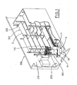
- Figure 1 illustrates a possible configuration of the shop, which is constituted by a unit 210 for receiving and dispensing the objects, by a plurality of storage units 201 formed by shelving 220, which is suitably arranged on the basis of the available space and the possibilities for moving the handling and conveying unit 100, and by the moving and stabilising system 1, which extends longitudinally in relation to the extension of the shelving 220.
- FIG. 1 The example of configuration shown in figure 1 is intentionally rather basic, but the structure of the shelving 220, and consequently of the system for moving 1, can be much more complex and articulated, extending to a number of rows which may be parallel to, or divergent from, one other, or may extend in a grid fashion, according to the size and layout of the premises where they are installed.
- the shelving 220 provides support surfaces 2 for the objects which define a series of housings of different heights, which optimally receive objects having different bulk, rigidity and weight.
- the handling and conveying unit 100 (see also figure 2 ) comprises a mobile, self-stabilising base 10 which is controlled by a computer which allows the unit 100 to access all the support surfaces 2 of the shop and the receiving and dispensing unit 210.
- the position of the objects on the relative support surfaces 2, together with general positional information about the objects and management strategies for stocking the shop and selling the objects, are managed by an external processor using substantially known techniques and modalities, which however go beyond the scope of this invention.
- the system 1 comprises, in particular, one or more modular linear guide elements 5, which are fixedly mounted on a support surface 202 of the shop 200, for example the floor.
- the guide element 5 is designed to guide the mobile base 10 along an operating trajectory concerning the storage units 201, on command of a central processor through a local computerised control unit.
- a single guide element 5 is shown, as the shop 200 floor plan represented is simple.
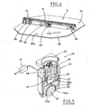
- Each guide element 5 comprises a structural plane 51 (see figures 2 and 3 ) which extends longitudinally, is arranged resting on the floor 202, and provides a substantially level movement surface for the mobile base 10.
- the structural plane 51 in turn comprises an upper layer 51 a made of sheet metal, and a lower layer 52 made of a compressible polymer material having a high friction coefficient.
- the lower layer 52 is preferably constituted by two layers of polymer material having different characteristics.
- An inner layer, which is in contact with the upper layer 51, is less compressible and is better suited to supporting concentrated loads, while an outer layer is more compressible and has a higher friction coefficient, and further, compensates for anomalies in the planarity of the floor 202 upon which it rests.
- the structural plane 51 further comprises a pair of rolling tracks 53, which are arranged longitudinally at the sides of the structural plane 51, and are made with reinforced metallic material to perform functions which will become clear later in the description.
- the linear guide element 5 further comprises a monorail profile 55, constrained longitudinally to the structural plane 51 and designed to guide the mobile base 10 in a movement direction thereof.
- the monorail guide 55 in the embodiment illustrated in the figures, is made using a metal section bar having a quadrangular cross-section, and is centrally arranged on the structural plane 51.
- the upper surface of the monorail guide 55 supports a linear power supply distributor 56, which supplies electric power to the mobile base 10.
- This distributor 56 which is preferably of a substantially known type having drag brushes, supplies power continuously and efficiently.
- the system 1 further comprises one or more rotatable shunting elements 6 (see figure 4 ), which are also arranged resting on the floor 202 and reciprocally connect two or more of the linear guide elements 5 described above. They provide guiding continuity for the mobile base 10, which can engage with them after having left the linear guide elements 5, in order then to be shunted towards another guide element 5, or to be rotated by 180°, and subsequently return to the original guide element 5 oriented facing a shelving located on the opposite side to the guide element 5.
- one or more rotatable shunting elements 6 see figure 4
- They provide guiding continuity for the mobile base 10, which can engage with them after having left the linear guide elements 5, in order then to be shunted towards another guide element 5, or to be rotated by 180°, and subsequently return to the original guide element 5 oriented facing a shelving located on the opposite side to the guide element 5.
- Each shunting element 6 rotates, whether it is empty or carrying the mobile base 10.
- Each shunting element 6 comprises a segment of monorail profile 61 mounted rotatably around a central hub 62 on a portion of structural plane 67, which structural plane 67 is arranged resting on the floor 202.
- the portion of structural plane 67 is provided by a shaped plate of suitably thick sheet metal which, constrained to its surface facing the floor 202, bears a lower layer 67 made of compressible polymer material with a high friction coefficient.
- the lower layer can be made like the lower layer of the structural plane 52 of the above-described linear guide element 5.
- the segment of monorail profile 61 also exhibits a hollow, quadrangular cross-section.
- a gear reducer group 63 is provided, which is mechanically linked to the hub 62 by means of a crown wheel and pinion group, designed to make the monorail profile 61 rotate on the hub 62.
- the gear reducer group 63 rotates the monorail segment 62 when the monorail segment 62 is free, that is when the handling unit 100 is not engaged with it; such rotations become necessary, for example, in order to vary the connections between different linear guide elements 5 leading to the same shunting element 6. If a handling unit is engaged to the shunting element 6, and needs to rotate for any reason, it will preferably do so using its own means, as the rest of the description will make clear.
- the gear reducer 63 is also provided with a positional control device, which is not illustrated since it is of known type, for example an encoder connected to the control processor of the handling unit and/or the external management processor of the entire structure, in order to inform the processors about the exact angular position assumed by the monorail segment 62. This is particularly important when the handling unit is engaged in rotating the shunting element 6. In this case, thanks to the information received from the positional control device of the gear reducer 63, it can at any time be aware of its own angulation with respect to all the linear guide elements leading to the shunting element 6.
- a segment 64 of linear power supply distributor is provided, which provides power to the mobile base when the mobile base is engaged with the shunting element 6, and disengaged from the linear guide elements 5.
- the distributor segment 64 is shaped exactly like the distributor 56 provided in the linear guide element 5, and is continuous with the linear guide element 5 when the shunting element 6 is aligned there-with.
- a pair of sliding ball-bearing groups 65 is mounted, which are arranged with the balls in contact with the floor 202, and which are designed to support the profile 61 and facilitate its movements of rotation.
- An electromagnetic bolt 66 is also provided inside the monorail profile, which bolt 66 is electrically connected to the control unit and can be activated by the control unit to engage, when the profile 61 is in predetermined operating positions, in corresponding holes 66a which are afforded in the portion of structural plane 67.
- the system 1 further comprises drive and positional control organs 20 of the mobile base 10 which are arranged in the lower part of the mobile base 10 and lead the mobile base 10 on the operating trajectories along the guide elements 5 and shunting elements 6.
- the drive and positional control organs comprise a pair of drive wheels 21, mounted on the lower part of the mobile base 10 in symmetrical positions with respect to the axis of rotation of the mobile base.
- the drive wheels 21 are powered independently of each other by means of position-and torque-controlled motors, for example brushless motors, controlled in a known way by the control unit.
- the drive wheels 21 can be activated in the same direction and at the same speed, in either direction, to move the mobile base 10 forwards or backwards; they can be operated in opposite directions to enable the base 10 to rotate about its own axis, for example when the mobile base 10 is on a shunting element 6; or they can be operated with minimal speed differences to control the exact position of the base 10 and compensate for any deviations from the optimal advancement position.
- the optimal position is defined by position control organs, comprising two pairs of guide wheels 23 and sensor means 25.
- the guide wheels 23 are rotatably mounted in pairs on the lower part of the mobile base 10, and are horizontal and idle on respective supports 24, which extend downwardly from the lower surface of the mobile base 10.
- the guide wheels 23 are arranged on opposite sides of the monorail profile 55, and rest against the lateral surfaces of the monorail profile 55.
- the two pairs of guide wheels 23 are conveniently arranged at a distance from each other, respectively in the front part and rear part of the base 10 and aligned with the monorail profile 55, in such a way that they keep the base 10 substantially aligned with the monorail profile 55.
- the sensor means 25 detect any deviations in the position of the mobile base 10 from the optimal position of alignment with the monorail profile 55.
- the sensor means 25 comprise an extensometer which detects the load of the guide wheels 23 on the monorail profile 55, by measuring the deformation of the support 24 of the guide wheels.
- the control unit of the mobile base 10 to correct deviations from the ideal trajectory, simply by modifying the speed of each of the drive wheels in order to minimise the angular error of the trajectory.
- all the mechanical parts of the mobile base 10 to be advantageously designed with dimensional tolerances that are not particularly tight, thus containing design and production costs.
- Further sensors of the photoelectric, laser or other type can be provided to contribute in a known way to better defining the deviations of the base 10 from the optimal position thereof, thus enabling the control unit to compensate for them by acting on the drive wheels 21.
- the system 1 exhibits stabiliser organs 30, designed to stabilise the position of the mobile base 10 during the operations of recognising and handling objects which the robotic unit 100 performs.
- the stabiliser organs 30 are constituted by four lockable feet with ball bearings s arranged on the lower part of the mobile base 10, at the corners thereof.
- Each ball bearing lockable foot 30 (see also figure 5 ) consists of an internally hollow body 31 of a substantially cylindrical shape, which is provided in its upper part with a flange 32 which enables it to be constrained to the lower surface of the mobile base 10.
- a cylindrically symmetrical mobile block 33 is provided, the lower part of which affords a semi-spherical cavity 34.
- the semi-spherical cavity 34 receives a support sphere 35 of large dimensions, which rolls within the cavity 34 with the interposition of a plurality of small-diameter rolling balls 36.
- projecting elements 34a are provided in the internal mobile block 33, which prevent the rolling balls from escaping from the cavity 34.
- the upper part of the mobile block 33 is internally hollow.
- a cylindrically symmetric internal block 37 which is mounted coaxial with the body 31 and with the mobile block 33, is constrained to the upper part of the body 31.
- the lower part of the fixed internal block 37 is slidingly inserted in the hollow upper part 36a of the mobile block 33, thus defining a compensation chamber 40 having variable volume.
- the fixed block 37 further affords a through axial conduit 39 which opens into the compensation chamber 40.
- a compressible coil spring 45 is mounted coaxially with the fixed internal block 37 and operates in contrast with the mobile internal block 33.
- the compensation chamber 40 is designed to receive hydraulic fluid, which is supplied through the axial conduit 39 by an accumulation tank (not illustrated), which supplies the liquid and receives the liquid within itself, respectively as a consequence of increases or diminutions in the volume of the compensation chamber 40.
- an accumulation tank not illustrated
- These variations are due to the excursions of the mobile block 33 caused by corresponding variations of load on the ball-equipped foot 30, by effect of the centre of gravity of the mobile base 10 shifting during the object handling operations.
- the axial conduit 39 fluidly communicates with the accumulation tank with the interposition of a check valve 41, which is illustrated only schematically in figure 5 and is activated by electromagnetic means.
- the check valve is electrically connected to the control unit and can be operated by the control unit to set the volume of the compensation chamber 40. In this way, the position of the mobile internal block 33, and thus the overall height of the foot 30 with the ball bearing are also set.
- the mobile base can be stably blocked in this position, to enable the handling organs to perform the operations of recognising and collecting the objects in an extremely precise way.
- the system 1 is modular so that it can adapt to all the possible dimensional and structural requirements of the premises where the automated shop or store is installed.
- it comprises a plurality of the above-mentioned linear guide elements 5, connected to one another by means of a plurality of shunting elements 6.
- the system of the present invention provides multiple advantages. In the first place it allows contemporaneous use of a number of robotic units on a same storage structure, since the various units can be distributed throughout the nodes of the guide structure by means of the shunting elements 6.
- robotic units can be made to perform handling operations in a very simple and effective way on both sides of the storage structure.
- a further advantage is the remarkable precision which the drive and positional control devices described above provide for guiding and positioning the mobile base.
- Another advantage is that the position of the base guide, and thus that of the robotic unit, can be made particularly stable.
- Another advantage is that the structural plane thus obtained makes it possible to arrange the entire guide structure resting on the floor 202, without damaging the integrity of the floor 202.
Landscapes
- Engineering & Computer Science (AREA)
- Transportation (AREA)
- Structural Engineering (AREA)
- Civil Engineering (AREA)
- Life Sciences & Earth Sciences (AREA)
- Geology (AREA)
- Mechanical Engineering (AREA)
- Manipulator (AREA)
- Warehouses Or Storage Devices (AREA)
- Transplanting Machines (AREA)
Claims (23)
- Un système de déplacement et de stabilisation d'une base mobile, comprenant une base mobile qui fait partie d'une unité robotisée de manipulation (100) pour déplacer des objets dans un magasin automatisé ou un entrepôt automatisé (200) comprenant une pluralité d'unités (201) de stockage des objets, et ladite base mobile (10) comprend une plateforme (11) qui supporte des organes (110) destinés à reconnaître et à manipuler les objets, le système étant caractérisé en ce qu'il comprend :au moins un élément de guidage linéaire (5), modulaire, qui est assujetti à une surface de support (202) du magasin ou entrepôt (200), et qui guide la base mobile (10) le long de trajectoires opérationnelles qui suivent les unités de stockage (201) ; au moins un élément de manoeuvre (6) rotatif, disposé sur la surface de support (202) au niveau d'une extrémité de l'élément de guidage (5) et destiné à relier réciproquement deux ou plus éléments de guidage (5) disposés à un angle prédéfini l'un par rapport à l'autre, de manière à manoeuvrer la base mobile (10) entre divers éléments de guidage linéaire (5), ou pour permettre à la base mobile (10) de venir nouvellement en prise avec l'élément linéaire à une orientation différente ; des organes de traction et de contrôle positionnel (20), disposés dans une partie inférieure de la base mobile (10), qui transportent ladite base mobile (10) sur les éléments de guidage (5) et les éléments de manoeuvre (6), et définissent une position de la base mobile (10) elle-même ; des organes de stabilisation (30), disposés périphériquement dans une partie inférieure de la base mobile (10), qui stabilisent la position de celle-ci pendant les opérations de manipulation d'objets de l'unité robotisée (100) ; la base mobile (10) et l'élément de manoeuvre (6) étant asservis à une unité de contrôle informatisée, qui gère le fonctionnement de ceux-ci selon les exigences opérationnelles du magasin ou entrepôt automatisé, oùl'élément de guidage linéaire (5) comprend : un plan structurel (51), qui est disposé en appui sur la surface de support (202), fournissant à la base mobile (10) une surface de déplacement essentiellement plane, et fournissant aux organes de stabilisation (30) une surface de support ; etcomprend un profilé monorail (55), qui est longitudinalement assujetti au plan structurel (51) et guide la base mobile (10) dans une direction de déplacement de celle-ci.
- Le système selon la revendication 1, caractérisé en ce que le plan structurel (51) comprend au moins une couche inférieure (52) réalisée dans un matériau polymère compressible à haut coefficient de frottement.
- Le système selon la revendication 1, caractérisé en ce que le plan structurel (51) comprend une paire de pistes de roulement (53), qui sont disposées longitudinalement sur des côtés dudit plan structurel (51) et supportent l'action des organes de stabilisation (30).
- Le système selon la revendication 1, caractérisé en ce que le profilé monorail (55) supporte un distributeur d'alimentation électrique linéaire (56) fournissant l'alimentation électrique à la base mobile (10).
- Le système selon la revendication 1, caractérisé en ce que le profilé monorail (55) présente une section essentiellement quadrangulaire.
- Le système selon la revendication 1, caractérisé en ce que l'élément de manoeuvre (6) comprend un segment de profilé monorail (61) disposé horizontalement et monté de façon pivotante au niveau d'un moyeu (62) à axe vertical, ledit segment de profilé monorail (61) reçoit et tourne la base mobile (10) autour dudit axe vertical, sur commande de l'unité de contrôle.
- Le système selon la revendication 6, caractérisé en ce que le segment de profilé monorail (61) comprend en outre un groupe réducteur à engrenage (63), qui est relié mécaniquement au moyeu (62) et définit des rotations d'amplitude prédéfinie de ce même moyeu (62) autour de l'axe vertical susmentionné.
- Le système selon la revendication 7, caractérisé en ce que le groupe réducteur à engrenage (63) est doté de moyens de contrôle positionnel qui surveillent en permanence la position angulaire du segment de profilé monorail (61).
- Le système selon la revendication 6 ou 7, caractérisé en ce que le segment de profilé monorail (61) comprend en outre un segment de distributeur d'alimentation électrique linéaire (64) qui fournit l'alimentation électrique à la base mobile (10) quand cette même base mobile (10) est en prise avec l'élément de manoeuvre (6).
- Le système selon la revendication 6, caractérisé en ce que le segment de profilé monorail (61) comprend, à côté de ses extrémités, une paire de groupes de coulissement à billes (65) qui supportent ledit segment de profilé monorail (61) et facilitent les mouvements de rotation de celui-ci.
- Le système selon la revendication 6, caractérisé en ce qu'au moins un verrou électromagnétique (66), destiné à verrouiller le segment de profilé monorail (61) au niveau de positions opérationnelles prédéfinies, est en outre prévu dans ledit segment de profilé monorail (61).
- Le système selon la revendication 1, caractérisé en ce que l'élément de manoeuvre (6) comprend en outre une portion de plan structurel (67), qui est disposée sous le segment de profilé monorail (61), en appui sur la surface de support (202) et fournissant à la base mobile (10) une surface de déplacement essentiellement plane.
- Le système selon la revendication 12, caractérisé en ce que la portion de plan structurel (67) comprend au moins une couche inférieure (68) réalisée dans un matériau polymère compressible à haut coefficient de frottement.
- Le système selon la revendication 1, caractérisé en ce que les organes de traction et de contrôle positionnel (20) comprennent : une paire de roues motrices (21) qui sont montées sur la partie inférieure de la base mobile (10) dans des positions symétriques par rapport à l'axe de rotation de la base mobile (10) elle-même ; au moins une paire de roues de guidage (23), montées sur la partie inférieure de la base mobile (10) et opérant en contact avec des surfaces latérales de l'élément de guidage linéaire (5), de manière à maintenir la position de la base mobile (10) ; et des moyens capteurs (25), reliés électriquement à l'unité de contrôle et destinés à détecter des écarts de position de la base mobile (10) par rapport à la position optimale de celle-ci.
- Le système selon la revendication 14, caractérisé en ce que les roues motrices sont motorisées indépendamment par des moteurs contrôlés en position et en couple.
- Le système selon la revendication 14, caractérisé en ce que deux paires de roues de guidage (23) sont prévues, chaque paire étant disposée avec les roues les unes en face des autres sur des surfaces opposées de l'élément de guidage (5), les deux paires étant disposées au niveau des parties avant et arrière de la base mobile (10).
- Le système selon la revendication 15 ou 16, caractérisé en ce que chacune des roues de guidage (23) est montée sur un support (24) qui s'étend à partir de la surface inférieure de la base mobile (10), et est dotée d'une rotation libre autour d'un axe vertical.
- Le système selon la revendication 15, caractérisé en ce que les moyens capteurs (25) comprennent pour chacune des roues de guidage au moins un extensomètre, qui détecte des déformations des supports (24) des roues de guidage pour permettre une compensation des écarts par rapport à une trajectoire idéale.
- Le système selon la revendication 1, caractérisé en ce que les organes de stabilisation (30) comprennent une pluralité de pieds presseurs à billes à excursion blocable.
- Le système selon la revendication 19, caractérisé en ce que quatre des pieds presseurs à billes (30) sont prévus au niveau des angles de la base mobile (10).
- Le système selon la revendication 19 ou 20, caractérisé en ce que chacun des pieds presseurs à billes (30) comprend : un corps (31) qui est intérieurement creux, doté supérieurement d'une bride (32) qui en permet la fixation à la surface inférieure de la base mobile (10); un bloc mobile intérieur (33) présentant intérieurement une cavité (34) logeant une bille de support (35) avec une pluralité de billes de roulement (36) interposées, la partie supérieure (36a) du bloc mobile (33) étant intérieurement creuse ; un bloc fixe intérieur (37), qui est monté coaxialement au corps (31) et doté intérieurement d'un conduit axial débouchant (39), la partie inférieure du bloc fixe intérieur (37) étant insérée de façon coulissante dans la partie supérieure creuse (36a), définissant ainsi une chambre de compensation (40), qui reçoit un fluide hydraulique à travers le conduit axial débouchant (39); un ressort à compression (45), qui est monté coaxialement au bloc fixe intérieur (37) et agit en opposition avec le bloc mobile intérieur (33).
- Le système selon la revendication 21, caractérisé en ce que chacun des pieds presseurs à billes (30) comprend en outre un clapet de non-retour (41) mis en communication de fluide avec le conduit axial débouchant (39) et avec un réservoir d'accumulation de fluide hydraulique, ledit clapet de non-retour (41) peut être actionné par l'unité de contrôle pour définir une position du bloc mobile intérieur (33) et stabiliser la base mobile (10).
- Le système selon la revendication 1, caractérisé en ce qu'il comprend une pluralité d'éléments de guidage linéaire (5) réciproquement reliés par une pluralité desdits éléments de manoeuvre (6).
Applications Claiming Priority (2)
| Application Number | Priority Date | Filing Date | Title |
|---|---|---|---|
| IT000154A ITBO20070154A1 (it) | 2007-03-08 | 2007-03-08 | Sistema per la movimentazione e la stabilizzazione di una base mobile |
| PCT/IB2008/000477 WO2008107770A1 (fr) | 2007-03-08 | 2008-03-04 | Système de déplacement et de stabilisation d'une base mobile |
Publications (2)
| Publication Number | Publication Date |
|---|---|
| EP2121502A1 EP2121502A1 (fr) | 2009-11-25 |
| EP2121502B1 true EP2121502B1 (fr) | 2014-05-28 |
Family
ID=39636886
Family Applications (1)
| Application Number | Title | Priority Date | Filing Date |
|---|---|---|---|
| EP08719211.8A Ceased EP2121502B1 (fr) | 2007-03-08 | 2008-03-04 | Système de déplacement et de stabilisation d'une base mobile |
Country Status (5)
| Country | Link |
|---|---|
| US (1) | US8161887B2 (fr) |
| EP (1) | EP2121502B1 (fr) |
| JP (1) | JP5351055B2 (fr) |
| IT (1) | ITBO20070154A1 (fr) |
| WO (1) | WO2008107770A1 (fr) |
Families Citing this family (10)
| Publication number | Priority date | Publication date | Assignee | Title |
|---|---|---|---|---|
| ITBO20070154A1 (it) * | 2007-03-08 | 2008-09-09 | Smv S R L | Sistema per la movimentazione e la stabilizzazione di una base mobile |
| EP3088347B1 (fr) * | 2008-09-08 | 2021-08-04 | Swisslog Evomatic GMBH | Appareil de commande de rayonnage |
| US8849634B2 (en) * | 2012-02-01 | 2014-09-30 | Palo Alto Research Center Incorporation | Method for identifying the maximal packing density of shifting-tiles automated warehouses |
| US10026044B1 (en) | 2012-09-10 | 2018-07-17 | Amazon Technologies, Inc. | System and method for arranging an order |
| US9663293B2 (en) * | 2012-10-08 | 2017-05-30 | Amazon Technologies, Inc. | Replenishing a retail facility |
| US9221471B2 (en) * | 2013-02-20 | 2015-12-29 | Solarcity, Inc. | Monorail vehicle apparatus with gravity-augmented contact load |
| EP3056454A4 (fr) * | 2013-10-11 | 2017-05-17 | Hitachi, Ltd. | Système de robot de transfert |
| TWI743389B (zh) * | 2018-08-30 | 2021-10-21 | 張志峰 | 運輸設備 |
| CN113213084B (zh) * | 2021-05-14 | 2022-06-28 | 湘潭大学 | 一种人工移动机车货箱的装置 |
| CN118025701A (zh) * | 2024-04-12 | 2024-05-14 | 湖北三丰小松物流技术有限公司 | 一种自适应升降导向的四向穿梭车 |
Family Cites Families (22)
| Publication number | Priority date | Publication date | Assignee | Title |
|---|---|---|---|---|
| US3212654A (en) * | 1963-11-21 | 1965-10-19 | Lansing Bagnall Ltd | Apparatus for loading and unloading goods |
| US3255899A (en) * | 1963-12-23 | 1966-06-14 | F F Mengel Co | Material handling apparatus |
| US4007843A (en) * | 1972-07-17 | 1977-02-15 | Rapistan, Incorporated | Multi-aisle warehouse system with mobile lift having control means for an article transfer vehicle |
| US3800963A (en) * | 1972-12-04 | 1974-04-02 | E Holland | Material storage and handling system |
| US4119208A (en) * | 1975-04-16 | 1978-10-10 | Norbert Karl Acker | Arrangement for the movement of objects within the deposit area of shelves |
| US4298305A (en) * | 1978-11-22 | 1981-11-03 | Columbia Machine, Inc. | Method and apparatus for transferring loads |
| JPS564869A (en) * | 1979-06-26 | 1981-01-19 | Taisei Corp | Managing system for commodity of many types, many items and many number of quantities |
| US4505630A (en) * | 1979-12-17 | 1985-03-19 | Besser Company | Article transfer apparatus |
| DE3115479C2 (de) * | 1981-04-16 | 1985-05-09 | Mannesmann AG, 4000 Düsseldorf | Drehvorrichtung für ein Regalförderzeug |
| US4553893A (en) * | 1983-12-05 | 1985-11-19 | Besser Company | Article transfer apparatus |
| IT1208234B (it) * | 1987-01-23 | 1989-06-12 | M P Meccanica Di Precisione Sa | Bine vuote e piene in e da macchine robot programmabile di tipo filogui bobinatrici e da ed in rispettivi dato e o radiocomandato per il cari magazzini di alimentazione e di racco e lo scarico automatico delle bo colta |
| GB2201938B (en) * | 1987-03-11 | 1991-09-04 | Honda Motor Co Ltd | Automated loading/unloading equipment |
| EP0310714B1 (fr) * | 1987-11-30 | 1990-07-25 | Magcon Beheer B.V. | Système de stockage pour palettes |
| JPH0747403B2 (ja) * | 1990-05-22 | 1995-05-24 | インベストロニカ・ソシエダッド・アノニマ | プログラム制御による箱、コンテナ等の操作・移送装置 |
| JPH04333402A (ja) * | 1991-05-01 | 1992-11-20 | Japan Nuclear Fuel Co Ltd<Jnf> | スタッカーストレージ |
| US6042321A (en) * | 1996-07-30 | 2000-03-28 | Westafalia Technologies, Inc. | Automated storage and retrieval system for palletless dairy cases |
| JPH11139126A (ja) * | 1997-11-05 | 1999-05-25 | Murata Mach Ltd | 無人搬送車 |
| JPH11348783A (ja) * | 1998-06-08 | 1999-12-21 | Hitachi Kiden Kogyo Ltd | 走行路の分岐・合流装置 |
| JP3511619B2 (ja) * | 1999-10-28 | 2004-03-29 | 村田機械株式会社 | 有軌道台車システム |
| US6652213B1 (en) * | 2000-09-08 | 2003-11-25 | California Natural Products | Automated warehousing system and method |
| WO2007007354A1 (fr) * | 2005-07-07 | 2007-01-18 | Marco Martelli | Système de gestion général d’entreposage de palettes, véhicules automobiles, etc. |
| ITBO20070154A1 (it) * | 2007-03-08 | 2008-09-09 | Smv S R L | Sistema per la movimentazione e la stabilizzazione di una base mobile |
-
2007
- 2007-03-08 IT IT000154A patent/ITBO20070154A1/it unknown
-
2008
- 2008-03-04 WO PCT/IB2008/000477 patent/WO2008107770A1/fr not_active Ceased
- 2008-03-04 EP EP08719211.8A patent/EP2121502B1/fr not_active Ceased
- 2008-03-04 JP JP2009552290A patent/JP5351055B2/ja not_active Expired - Fee Related
- 2008-03-04 US US12/529,266 patent/US8161887B2/en not_active Expired - Fee Related
Also Published As
| Publication number | Publication date |
|---|---|
| ITBO20070154A1 (it) | 2008-09-09 |
| JP5351055B2 (ja) | 2013-11-27 |
| EP2121502A1 (fr) | 2009-11-25 |
| US20100031845A1 (en) | 2010-02-11 |
| US8161887B2 (en) | 2012-04-24 |
| WO2008107770A1 (fr) | 2008-09-12 |
| JP2010520134A (ja) | 2010-06-10 |
Similar Documents
| Publication | Publication Date | Title |
|---|---|---|
| EP2121502B1 (fr) | Système de déplacement et de stabilisation d'une base mobile | |
| US11661279B2 (en) | Autonomous transports for storage and retrieval systems | |
| US11952214B2 (en) | Automated bot transfer arm drive system | |
| US10280000B2 (en) | Suspension system for autonomous transports | |
| US8425173B2 (en) | Autonomous transports for storage and retrieval systems | |
| CN102341323B (zh) | 储存用设备,尤其是用于该设备的仓库货架和装卸机械 | |
| WO2004103863A1 (fr) | Dispositif et procede dans un systeme de stockage circulaire, et dispositif de transfert dans l'unite de stockage circulaire | |
| US12570469B2 (en) | Systems and methods for providing mobile shuttle load handling systems |
Legal Events
| Date | Code | Title | Description |
|---|---|---|---|
| PUAI | Public reference made under article 153(3) epc to a published international application that has entered the european phase |
Free format text: ORIGINAL CODE: 0009012 |
|
| 17P | Request for examination filed |
Effective date: 20090923 |
|
| AK | Designated contracting states |
Kind code of ref document: A1 Designated state(s): AT BE BG CH CY CZ DE DK EE ES FI FR GB GR HR HU IE IS IT LI LT LU LV MC MT NL NO PL PT RO SE SI SK TR |
|
| DAX | Request for extension of the european patent (deleted) | ||
| 17Q | First examination report despatched |
Effective date: 20130829 |
|
| GRAP | Despatch of communication of intention to grant a patent |
Free format text: ORIGINAL CODE: EPIDOSNIGR1 |
|
| INTG | Intention to grant announced |
Effective date: 20140127 |
|
| GRAS | Grant fee paid |
Free format text: ORIGINAL CODE: EPIDOSNIGR3 |
|
| GRAA | (expected) grant |
Free format text: ORIGINAL CODE: 0009210 |
|
| AK | Designated contracting states |
Kind code of ref document: B1 Designated state(s): AT BE BG CH CY CZ DE DK EE ES FI FR GB GR HR HU IE IS IT LI LT LU LV MC MT NL NO PL PT RO SE SI SK TR |
|
| REG | Reference to a national code |
Ref country code: GB Ref legal event code: FG4D |
|
| REG | Reference to a national code |
Ref country code: CH Ref legal event code: EP |
|
| REG | Reference to a national code |
Ref country code: AT Ref legal event code: REF Ref document number: 670282 Country of ref document: AT Kind code of ref document: T Effective date: 20140615 |
|
| REG | Reference to a national code |
Ref country code: IE Ref legal event code: FG4D |
|
| REG | Reference to a national code |
Ref country code: DE Ref legal event code: R096 Ref document number: 602008032486 Country of ref document: DE Effective date: 20140710 |
|
| REG | Reference to a national code |
Ref country code: CH Ref legal event code: NV Representative=s name: RIEDERER HASLER AND PARTNER PATENTANWAELTE AG, LI |
|
| REG | Reference to a national code |
Ref country code: AT Ref legal event code: MK05 Ref document number: 670282 Country of ref document: AT Kind code of ref document: T Effective date: 20140528 |
|
| REG | Reference to a national code |
Ref country code: NL Ref legal event code: VDEP Effective date: 20140528 |
|
| REG | Reference to a national code |
Ref country code: LT Ref legal event code: MG4D |
|
| PG25 | Lapsed in a contracting state [announced via postgrant information from national office to epo] |
Ref country code: NO Free format text: LAPSE BECAUSE OF FAILURE TO SUBMIT A TRANSLATION OF THE DESCRIPTION OR TO PAY THE FEE WITHIN THE PRESCRIBED TIME-LIMIT Effective date: 20140828 Ref country code: CY Free format text: LAPSE BECAUSE OF FAILURE TO SUBMIT A TRANSLATION OF THE DESCRIPTION OR TO PAY THE FEE WITHIN THE PRESCRIBED TIME-LIMIT Effective date: 20140528 Ref country code: GR Free format text: LAPSE BECAUSE OF FAILURE TO SUBMIT A TRANSLATION OF THE DESCRIPTION OR TO PAY THE FEE WITHIN THE PRESCRIBED TIME-LIMIT Effective date: 20140829 Ref country code: FI Free format text: LAPSE BECAUSE OF FAILURE TO SUBMIT A TRANSLATION OF THE DESCRIPTION OR TO PAY THE FEE WITHIN THE PRESCRIBED TIME-LIMIT Effective date: 20140528 Ref country code: LT Free format text: LAPSE BECAUSE OF FAILURE TO SUBMIT A TRANSLATION OF THE DESCRIPTION OR TO PAY THE FEE WITHIN THE PRESCRIBED TIME-LIMIT Effective date: 20140528 |
|
| PG25 | Lapsed in a contracting state [announced via postgrant information from national office to epo] |
Ref country code: LV Free format text: LAPSE BECAUSE OF FAILURE TO SUBMIT A TRANSLATION OF THE DESCRIPTION OR TO PAY THE FEE WITHIN THE PRESCRIBED TIME-LIMIT Effective date: 20140528 Ref country code: SE Free format text: LAPSE BECAUSE OF FAILURE TO SUBMIT A TRANSLATION OF THE DESCRIPTION OR TO PAY THE FEE WITHIN THE PRESCRIBED TIME-LIMIT Effective date: 20140528 Ref country code: AT Free format text: LAPSE BECAUSE OF FAILURE TO SUBMIT A TRANSLATION OF THE DESCRIPTION OR TO PAY THE FEE WITHIN THE PRESCRIBED TIME-LIMIT Effective date: 20140528 Ref country code: HR Free format text: LAPSE BECAUSE OF FAILURE TO SUBMIT A TRANSLATION OF THE DESCRIPTION OR TO PAY THE FEE WITHIN THE PRESCRIBED TIME-LIMIT Effective date: 20140528 |
|
| PG25 | Lapsed in a contracting state [announced via postgrant information from national office to epo] |
Ref country code: PT Free format text: LAPSE BECAUSE OF FAILURE TO SUBMIT A TRANSLATION OF THE DESCRIPTION OR TO PAY THE FEE WITHIN THE PRESCRIBED TIME-LIMIT Effective date: 20140929 |
|
| PG25 | Lapsed in a contracting state [announced via postgrant information from national office to epo] |
Ref country code: DK Free format text: LAPSE BECAUSE OF FAILURE TO SUBMIT A TRANSLATION OF THE DESCRIPTION OR TO PAY THE FEE WITHIN THE PRESCRIBED TIME-LIMIT Effective date: 20140528 Ref country code: RO Free format text: LAPSE BECAUSE OF FAILURE TO SUBMIT A TRANSLATION OF THE DESCRIPTION OR TO PAY THE FEE WITHIN THE PRESCRIBED TIME-LIMIT Effective date: 20140528 Ref country code: CZ Free format text: LAPSE BECAUSE OF FAILURE TO SUBMIT A TRANSLATION OF THE DESCRIPTION OR TO PAY THE FEE WITHIN THE PRESCRIBED TIME-LIMIT Effective date: 20140528 Ref country code: ES Free format text: LAPSE BECAUSE OF FAILURE TO SUBMIT A TRANSLATION OF THE DESCRIPTION OR TO PAY THE FEE WITHIN THE PRESCRIBED TIME-LIMIT Effective date: 20140528 Ref country code: BE Free format text: LAPSE BECAUSE OF FAILURE TO SUBMIT A TRANSLATION OF THE DESCRIPTION OR TO PAY THE FEE WITHIN THE PRESCRIBED TIME-LIMIT Effective date: 20140528 Ref country code: SK Free format text: LAPSE BECAUSE OF FAILURE TO SUBMIT A TRANSLATION OF THE DESCRIPTION OR TO PAY THE FEE WITHIN THE PRESCRIBED TIME-LIMIT Effective date: 20140528 Ref country code: EE Free format text: LAPSE BECAUSE OF FAILURE TO SUBMIT A TRANSLATION OF THE DESCRIPTION OR TO PAY THE FEE WITHIN THE PRESCRIBED TIME-LIMIT Effective date: 20140528 |
|
| PG25 | Lapsed in a contracting state [announced via postgrant information from national office to epo] |
Ref country code: NL Free format text: LAPSE BECAUSE OF FAILURE TO SUBMIT A TRANSLATION OF THE DESCRIPTION OR TO PAY THE FEE WITHIN THE PRESCRIBED TIME-LIMIT Effective date: 20140528 Ref country code: PL Free format text: LAPSE BECAUSE OF FAILURE TO SUBMIT A TRANSLATION OF THE DESCRIPTION OR TO PAY THE FEE WITHIN THE PRESCRIBED TIME-LIMIT Effective date: 20140528 |
|
| REG | Reference to a national code |
Ref country code: DE Ref legal event code: R097 Ref document number: 602008032486 Country of ref document: DE |
|
| PLBE | No opposition filed within time limit |
Free format text: ORIGINAL CODE: 0009261 |
|
| STAA | Information on the status of an ep patent application or granted ep patent |
Free format text: STATUS: NO OPPOSITION FILED WITHIN TIME LIMIT |
|
| 26N | No opposition filed |
Effective date: 20150303 |
|
| REG | Reference to a national code |
Ref country code: DE Ref legal event code: R097 Ref document number: 602008032486 Country of ref document: DE Effective date: 20150303 |
|
| PG25 | Lapsed in a contracting state [announced via postgrant information from national office to epo] |
Ref country code: SI Free format text: LAPSE BECAUSE OF FAILURE TO SUBMIT A TRANSLATION OF THE DESCRIPTION OR TO PAY THE FEE WITHIN THE PRESCRIBED TIME-LIMIT Effective date: 20140528 |
|
| PG25 | Lapsed in a contracting state [announced via postgrant information from national office to epo] |
Ref country code: MC Free format text: LAPSE BECAUSE OF FAILURE TO SUBMIT A TRANSLATION OF THE DESCRIPTION OR TO PAY THE FEE WITHIN THE PRESCRIBED TIME-LIMIT Effective date: 20140528 Ref country code: LU Free format text: LAPSE BECAUSE OF FAILURE TO SUBMIT A TRANSLATION OF THE DESCRIPTION OR TO PAY THE FEE WITHIN THE PRESCRIBED TIME-LIMIT Effective date: 20150304 |
|
| REG | Reference to a national code |
Ref country code: FR Ref legal event code: PLFP Year of fee payment: 9 |
|
| PG25 | Lapsed in a contracting state [announced via postgrant information from national office to epo] |
Ref country code: IS Free format text: LAPSE BECAUSE OF FAILURE TO SUBMIT A TRANSLATION OF THE DESCRIPTION OR TO PAY THE FEE WITHIN THE PRESCRIBED TIME-LIMIT Effective date: 20140528 |
|
| PG25 | Lapsed in a contracting state [announced via postgrant information from national office to epo] |
Ref country code: MT Free format text: LAPSE BECAUSE OF FAILURE TO SUBMIT A TRANSLATION OF THE DESCRIPTION OR TO PAY THE FEE WITHIN THE PRESCRIBED TIME-LIMIT Effective date: 20140528 |
|
| REG | Reference to a national code |
Ref country code: FR Ref legal event code: PLFP Year of fee payment: 10 |
|
| PG25 | Lapsed in a contracting state [announced via postgrant information from national office to epo] |
Ref country code: BG Free format text: LAPSE BECAUSE OF FAILURE TO SUBMIT A TRANSLATION OF THE DESCRIPTION OR TO PAY THE FEE WITHIN THE PRESCRIBED TIME-LIMIT Effective date: 20140528 Ref country code: HU Free format text: LAPSE BECAUSE OF FAILURE TO SUBMIT A TRANSLATION OF THE DESCRIPTION OR TO PAY THE FEE WITHIN THE PRESCRIBED TIME-LIMIT; INVALID AB INITIO Effective date: 20080304 |
|
| PG25 | Lapsed in a contracting state [announced via postgrant information from national office to epo] |
Ref country code: TR Free format text: LAPSE BECAUSE OF FAILURE TO SUBMIT A TRANSLATION OF THE DESCRIPTION OR TO PAY THE FEE WITHIN THE PRESCRIBED TIME-LIMIT Effective date: 20140528 |
|
| REG | Reference to a national code |
Ref country code: FR Ref legal event code: PLFP Year of fee payment: 11 |
|
| PGFP | Annual fee paid to national office [announced via postgrant information from national office to epo] |
Ref country code: IE Payment date: 20190220 Year of fee payment: 12 |
|
| PGFP | Annual fee paid to national office [announced via postgrant information from national office to epo] |
Ref country code: DE Payment date: 20190913 Year of fee payment: 12 Ref country code: IT Payment date: 20190830 Year of fee payment: 12 Ref country code: FR Payment date: 20190820 Year of fee payment: 12 |
|
| PGFP | Annual fee paid to national office [announced via postgrant information from national office to epo] |
Ref country code: GB Payment date: 20190820 Year of fee payment: 12 |
|
| PGFP | Annual fee paid to national office [announced via postgrant information from national office to epo] |
Ref country code: CH Payment date: 20190827 Year of fee payment: 12 |
|
| REG | Reference to a national code |
Ref country code: DE Ref legal event code: R119 Ref document number: 602008032486 Country of ref document: DE |
|
| REG | Reference to a national code |
Ref country code: CH Ref legal event code: PL |
|
| PG25 | Lapsed in a contracting state [announced via postgrant information from national office to epo] |
Ref country code: IE Free format text: LAPSE BECAUSE OF NON-PAYMENT OF DUE FEES Effective date: 20200304 Ref country code: FR Free format text: LAPSE BECAUSE OF NON-PAYMENT OF DUE FEES Effective date: 20200331 Ref country code: DE Free format text: LAPSE BECAUSE OF NON-PAYMENT OF DUE FEES Effective date: 20201001 Ref country code: LI Free format text: LAPSE BECAUSE OF NON-PAYMENT OF DUE FEES Effective date: 20200331 Ref country code: CH Free format text: LAPSE BECAUSE OF NON-PAYMENT OF DUE FEES Effective date: 20200331 |
|
| GBPC | Gb: european patent ceased through non-payment of renewal fee |
Effective date: 20200304 |
|
| PG25 | Lapsed in a contracting state [announced via postgrant information from national office to epo] |
Ref country code: GB Free format text: LAPSE BECAUSE OF NON-PAYMENT OF DUE FEES Effective date: 20200304 |
|
| PG25 | Lapsed in a contracting state [announced via postgrant information from national office to epo] |
Ref country code: IT Free format text: LAPSE BECAUSE OF NON-PAYMENT OF DUE FEES Effective date: 20200304 |