EP2122117B1 - Ensemble fente à verrouillage activé par pression - Google Patents
Ensemble fente à verrouillage activé par pression Download PDFInfo
- Publication number
- EP2122117B1 EP2122117B1 EP08709444A EP08709444A EP2122117B1 EP 2122117 B1 EP2122117 B1 EP 2122117B1 EP 08709444 A EP08709444 A EP 08709444A EP 08709444 A EP08709444 A EP 08709444A EP 2122117 B1 EP2122117 B1 EP 2122117B1
- Authority
- EP
- European Patent Office
- Prior art keywords
- slot
- lock
- assembly
- lug
- move
- Prior art date
- Legal status (The legal status is an assumption and is not a legal conclusion. Google has not performed a legal analysis and makes no representation as to the accuracy of the status listed.)
- Not-in-force
Links
Images


Classifications
-
- E—FIXED CONSTRUCTIONS
- E21—EARTH OR ROCK DRILLING; MINING
- E21B—EARTH OR ROCK DRILLING; OBTAINING OIL, GAS, WATER, SOLUBLE OR MELTABLE MATERIALS OR A SLURRY OF MINERALS FROM WELLS
- E21B23/00—Apparatus for displacing, setting, locking, releasing or removing tools, packers or the like in boreholes or wells
- E21B23/004—Indexing systems for guiding relative movement between telescoping parts of downhole tools
- E21B23/006—"J-slot" systems, i.e. lug and slot indexing mechanisms
-
- E—FIXED CONSTRUCTIONS
- E21—EARTH OR ROCK DRILLING; MINING
- E21B—EARTH OR ROCK DRILLING; OBTAINING OIL, GAS, WATER, SOLUBLE OR MELTABLE MATERIALS OR A SLURRY OF MINERALS FROM WELLS
- E21B23/00—Apparatus for displacing, setting, locking, releasing or removing tools, packers or the like in boreholes or wells
- E21B23/04—Apparatus for displacing, setting, locking, releasing or removing tools, packers or the like in boreholes or wells operated by fluid means, e.g. actuated by explosion
- E21B23/0412—Apparatus for displacing, setting, locking, releasing or removing tools, packers or the like in boreholes or wells operated by fluid means, e.g. actuated by explosion characterised by pressure chambers, e.g. vacuum chambers
-
- E—FIXED CONSTRUCTIONS
- E21—EARTH OR ROCK DRILLING; MINING
- E21B—EARTH OR ROCK DRILLING; OBTAINING OIL, GAS, WATER, SOLUBLE OR MELTABLE MATERIALS OR A SLURRY OF MINERALS FROM WELLS
- E21B23/00—Apparatus for displacing, setting, locking, releasing or removing tools, packers or the like in boreholes or wells
- E21B23/04—Apparatus for displacing, setting, locking, releasing or removing tools, packers or the like in boreholes or wells operated by fluid means, e.g. actuated by explosion
- E21B23/0418—Apparatus for displacing, setting, locking, releasing or removing tools, packers or the like in boreholes or wells operated by fluid means, e.g. actuated by explosion specially adapted for locking the tools in landing nipples or recesses
-
- E—FIXED CONSTRUCTIONS
- E21—EARTH OR ROCK DRILLING; MINING
- E21B—EARTH OR ROCK DRILLING; OBTAINING OIL, GAS, WATER, SOLUBLE OR MELTABLE MATERIALS OR A SLURRY OF MINERALS FROM WELLS
- E21B23/00—Apparatus for displacing, setting, locking, releasing or removing tools, packers or the like in boreholes or wells
- E21B23/04—Apparatus for displacing, setting, locking, releasing or removing tools, packers or the like in boreholes or wells operated by fluid means, e.g. actuated by explosion
- E21B23/042—Apparatus for displacing, setting, locking, releasing or removing tools, packers or the like in boreholes or wells operated by fluid means, e.g. actuated by explosion using a single piston or multiple mechanically interconnected pistons
Definitions
- the present invention relates to locking apparatus for downhole tools, and more particularly, to a pressure activated locking slot assembly.
- a mandrel is held in the run-in-hole position by interaction of a lug with a J-slot
- To move the tool out of the run-in-hole position generally involves the application of torque and longitudinal force.
- Such an arrangement can be problematic in offshore or highly deviated sections of a well bore, where dragging forces on the tool string may create difficulty in estimating the proper torque to apply at the surface to obtain the desirable torque at the J-slot.
- a continuous J-slot wraps all the way around the mandrel and typically has two lugs, so that the direction of torque applied need not be reversed in order to actuate. Rather, the tool may simply be picked up and put back down to cycle.
- a problem may arise when running such a tool into an offshore or highly deviated well bore. Dragging of the tool string on the well bore may cause the mandrel move relatively upwardly and rotate with respect to the drag block assembly sufficiently to result in premature actuation of the J-slot assembly. If such premature actuation occurs, subsequent downward load on the tool string may rupture the tool elements, or the tool elements may be damaged by dragging along the well bore. In addition, premature actuation may result in the tool string jamming in the well bore.
- US 3,494,418 which is considered the clesest prior art, discloses an apparatus releasably coupling telescoping tubular members together in a well bore.
- US 5,381,862 discloses a coiled tubing operated full opening completion tool system for use in a well bore.
- the present invention relates to locking apparatus for downhole tools, and more particularly, to a pressure activated locking slot assembly.
- the invention provides a locking slot assembly defined by claim 1.
- the invention provides a downhole tool assembly defined by claim 9.
- the invention provides a method defined by claim 16. Further features are defined in the dependent claims.
- a locking slot assembly comprising: a slot; a lug configured to move within the slot; and a lock configured to prevent the lug from moving within the slot until a triggering event occurs; wherein the lock is further configured to allow the lug to move within the slot after the triggering event has occurred, so long as a predetermined condition is maintained.
- the triggering event is the application of a predetermined pressure
- the predetermined condition is a minimum pressure.
- the looking slot assembly further comprises an inner mandrel disposed at least partially within the lock; and a fluid chamber disposed between the lock and the inner mandrel. The fluid chamber is configured to expand upon application of the predetermined pressure, moving the lock and allowing the lug to move within the slot.
- a downhole tool assembly comprising: a sleeve having a slot; a lug rotator ring configured to move axially relative to the sleeve, the rotator ring having a lug configured to move within the slot; and a lock configured to prevent the lug from moving within the slot until a predetermined pressure is applied; and wherein the lock is further configured to allow the lug to move within the slot after the predetermined pressure has been applied, so long as a minimum pressure is maintained.
- the downhole tool assembly further comprises: an inner mandrel disposed at least partially within the lock; and a fluid chamber disposed between the lock and the inner mandrel. The fluid chamber is configured to expand upon application of the predetermined pressure, moving the lock and allowing the lug to move within the slot.
- a method of activating a downhole tool assembly as described above comprising: providing the downhole tool assembly in a well bore; applying a predetermined pressure to the downhole tool assembly; and moving the downhole tool assembly upward.
- a downhole tool assembly comprising a sleeve having a slot, a lug rotator ring configured to move axially relative to the sleeve, the rotator ring having a lug configured to move within the slot, and a lock configured to prevent the lug from moving within the slot until a predetermined pressure is applied, is described.
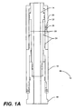
- Figure 1A is a side cross-sectional view showing one embodiment according to the present invention.
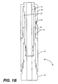
- Figure 1B is a side cross-sectional view of the embodiment illustrated in Fig. 1A , showing an unlocked position.
- Figure 2A is a side cross-sectional view showing another embodiment according to the present invention.
- Figure 2B is a side cross-sectional view of the embodiment illustrated in Fig. 2A , showing an unlocked position.
- Figure 3A is a side view showing one embodiment according to the present invention.
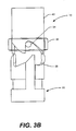
- Figure 3B is a side view of the embodiment illustrated in Fig. 3A , showing an unlocked position.
- locking slot assembly 10 is disposed adjacent to a lower end of a tool 12 (shown in Figure 2A ), which is of a kind known in the art, such as a valve, a packer, or any tool requiring different positions.
- Tool 12 may connect to a tool string (not shown) and the entire tool string may be positioned in a well bore.
- the well bore may be defined by a casing (not shown) and may be vertical, or the well bore may be deviated to any degree.
- Locking slot assembly 10 is illustrated below the tool 12.
- Tool 12 may include, or be attached to, an inner, actuating mandrel 14, which may be connected to the tool string.
- Locking slot assembly may include the actuating mandrel 14, attached at a lower end to bottom adapter 16.
- Actuating mandrel 14 and at least a portion of bottom adapter 16 may be situated within a fluid chamber case 18 and/or a lock 20.
- the fluid chamber case 18 and the lock 20 may be removably attached, fixedly attached, or even integrally formed with one another. Alternatively fluid chamber case 18 and lock 20 may be separate.
- At least one fluid chamber 22 may be situated between actuating mandrel 14 and lock 20. Fluid chamber 22 may be sealed via one or more seals 24, along with a rupture disk 26 situated in the lock 20. Air at atmospheric pressure may initially fill the fluid chamber 22. As the tool 12 is lowered into the well bore, hydrostatic pressure outside the tool 12 increases. Once the hydrostatic pressure reaches a predetermined value, the rupture disk 26 may rupture. After the rupture disk 26 has ruptured, the fluid outside the tool 12 will enter the tool 12 through a port 28 formed therein. The resulting increased pressure within the fluid chamber 22 will cause the fluid chamber 22 to expand (as shown in Figure 1B ). This expansion causes the longitudinal movement of the lock 20 with respect to the actuating mandrel 14, thus "unlocking" the locking slot assembly 10.
- Figures 3A and 3B which will be discussed below, further show the locked position and unlocked position respectively.
- FIG. 2A and 2B shown therein is an alternate embodiment of the locking slot assembly 10.
- This embodiment has no rupture disk 26. Instead, one or more shear pins 30 to prevent the lock 20 from moving until adequate pressure is present.
- a spring 32 may be included to keep the locking slot assembly 10 in an unlocked position. While the spring 32 shown is a coil spring, the spring 32 may be any biasing member. Likewise, the shear pin 30 may be a screw, spring, or any other shearable member.
- the embodiment of Figures 2A and 2B functions similarly to the embodiment of Figures 1A and 1B .
- An increase in pressure causes the lock 20 to move longitudinally with respect to the actuating mandrel 14, resulting in the unlocking of the locking slot assembly 10 (as shown in Figure 2B ).
- one or more lugs 34 may extend from a lug rotator ring 36 into a continuous slot 38 in a sleeve 40, thus providing locking assembly 10.
- pressure may cause the lock 20 to become unlocked.
- a locking portion 42 of the lock 20 occupies space within the slot 38, keeping the lugs 34 in a run-in-hole position, and preventing the lugs 34 from moving relative to the slot 38.
- the locking portion 42 moves out of the slot 38, allowing the lugs 34 to move relative to the slot 38 if there is an upward or downward force acting on the sleeve 40.
- the lock 20 In the run-in-hole, locked position, the lock 20 is in an upward position, in which lugs 34 are engaged with locking portion 42 of the lock 20. As the tool string is lowered into well bore, the locking slot assembly 10 will remain in the locked position shown in Figures 1A , 2A , and 3A , with the lock 20 preventing relative longitudinal movement of the lug rotator ring 36 with respect to the sleeve 40.
- the locking slot assembly 10 may be actuated, allowing the lug rotator ring 36 to move longitudinally with respect to the sleeve 40.
- the tool 12 may be set by pushing downward on the tool string, which lowers lug 34.
- the embodiment shown uses a j-slot, and in particular, shows a continuous J-slot.
- setting the tool may involve pushing downward on the tool string multiple times.
- the tool 12 may be set by up and down motion alone. This may prevent the operator from cycling through the slot and setting the tool 12 prematurely.
- the tool string is simply pulled upwardly out of the well bore. This will cause the lug 34 to re-engage the slot 38. Additionally, as the pressure outside the tool 12, and thus, the pressure within the fluid chamber 22 is reduced, the lock 20 may move back into the locked position, preventing any subsequent relative movement of the lug rotator ring 36 with respect to the sleeve 40.
- the lock 20 may be configured to allow the lug 34 to move within the slot after the triggering event has occurred, so long as a predetermined condition is maintained.
- the triggering event may be a timer reaching a predetermined value
- the predetermined condition may be that the timer has not yet reached a second predetermined value. Therefore, the present invention is well adapted to attain the ends and advantages mentioned. Furthermore, no limitations are intended to the details of construction or design herein shown, other than as described in the claims below.
Landscapes
- Geology (AREA)
- Life Sciences & Earth Sciences (AREA)
- Engineering & Computer Science (AREA)
- Mining & Mineral Resources (AREA)
- Environmental & Geological Engineering (AREA)
- Fluid Mechanics (AREA)
- Physics & Mathematics (AREA)
- General Life Sciences & Earth Sciences (AREA)
- Geochemistry & Mineralogy (AREA)
- Earth Drilling (AREA)
- Filling Or Discharging Of Gas Storage Vessels (AREA)
- Safety Valves (AREA)
- Portable Nailing Machines And Staplers (AREA)
- Processing Of Stones Or Stones Resemblance Materials (AREA)
Abstract
Claims (17)
- Ensemble à fente de verrouillage (10) comprenant:une fente (38) ;un ergot (34) configuré de façon à se déplacer à l'intérieur de la fente (38) ; etun verrou (20) configuré de façon à empêcher l'ergot (34) de se déplacer à l'intérieur de la fente (38) jusqu'à ce qu'un évènement de déclenchement se produise ;dans lequel le verrou (20) est configuré en outre de façon à permettre à l'ergot (34) de se déplacer à l'intérieur de la fente (38) après que l'évènement de déclenchement se soit produit, à condition qu'une condition prédéterminée soit maintenue,dans lequel l'évènement de déclenchement est l'application d'une pression prédéterminée,et dans lequel la condition prédéterminée est une pression minimum ;caractérisé en ce que l'ensemble à fente de verrouillage (10) comprend en outre :un mandrin interne (14) disposé au moins partiellement à l'intérieur du verrou (20) ;et une chambre à fluide (22) disposée entre le verrou (20) et le mandrin interne (14) ;dans lequel la chambre à fluide (22) est configurée de façon à augmenter de volume lors de l'application de la pression prédéterminée, déplaçant le verrou (20) et permettant à l'ergot (34) de se déplacer à l'intérieur de la fente (38).
- Ensemble à fente de verrouillage (10) selon la revendication 1, dans lequel la fente (38) comprend une fente en J.
- Ensemble à fente de verrouillage (10) selon la revendication 2, dans lequel la fente en J est une fente en J continue.
- Ensemble à fente de verrouillage (10) selon la revendication 1, dans lequel le verrou (20) comprend un ou plusieurs disques de rupture (26) configurés de façon à se rompre à la pression prédéterminée, permettant à l'ergot (34) de se déplacer à l'intérieur de la fente (38).
- Ensemble à fente de verrouillage (10) selon la revendication 1, dans lequel le verrou (20) comprend une ou plusieurs goupilles de cisaillement (30) configurées de façon à se cisailler à la pression prédéterminée, permettant à l'ergot (34) de se déplacer à l'intérieur de la fente (38).
- Ensemble à fente de verrouillage (10) selon la revendication 1, dans lequel le verrou (20) est configuré en outre de façon à empêcher encore une fois à l'ergot (34) de se déplacer à l'intérieur de la fente (38) si la pression minimum n'est pas maintenue.
- Ensemble à fente de verrouillage (10) selon la revendication 1, dans lequel la pression prédéterminée est une pression hydrostatique.
- Ensemble à fente de verrouillage (10) selon la revendication 1, dans lequel la pression minimum est une pression hydrostatique.
- Ensemble outil de fond de trou comprenant:un manchon (40) ayant une fente (38) ; ;une bague de rotation d'ergot (36) configurée de façon à se déplacer axialement par rapport au manchon (40), cette bague de rotation (36) ayant un ergot (34) configuré de façon à se déplacer à l'intérieur de la fente (38) ; etun verrou (20) configuré de façon à empêcher l'ergot de se déplacer à l'intérieur de la fente jusqu'à ce qu'une pression prédéterminée soit appliquée ; etdans lequel le verrou (20) est configuré en outre de façon à permettre à l'ergot (34) de se déplacer à l'intérieur de la fente (38) après que la pression prédéterminée a été appliquée, à condition qu'une pression minimum soit maintenue,caractérisé en ce que l'ensemble outil de fond de trou comprend en outre :un mandrin interne (14) disposé au moins partiellement à l'intérieur du verrou (20) ;et une chambre à fluide (22) disposée entre le verrou (20) et le mandrin interne (14),dans lequel la chambre à fluide (22) est configurée de façon à augmenter de volume lors de l'application de la pression prédéterminée, déplaçant le verrou (20) et permettant à l'ergot (34) de se déplacer à l'intérieur de la fente (38).
- Ensemble de fond de trou selon la revendication 9, dans lequel la fente (38) comprend une fente en J.
- Ensemble de fond de trou selon la revendication 10, dans lequel la fente en J est une fente en J continue.
- Ensemble de fond de trou selon la revendication 9, dans lequel le verrou (20) comprend un ou plusieurs disques de rupture (26) configurés de façon à se rompre à la pression prédéterminée, permettant à l'ergot (34) de se déplacer à l'intérieur de la fente (38).
- Ensemble de fond de trou selon la revendication 9, dans lequel le verrou (20) comprend une ou plusieurs goupilles de cisaillement (30) configurées de façon à se cisailler à la pression prédéterminée, permettant à l'ergot (34) de se déplacer à l'intérieur de la fente (38).
- Ensemble de fond de trou selon la revendication 9, dans lequel le verrou (20) est configuré en outre de façon à empêcher encore une fois à l'ergot (34) de se déplacer à l'intérieur de la fente (38) si la pression minimum n'est pas maintenue.
- Ensemble de fond de trou selon la revendication 9, dans lequel la pression prédéterminée est une pression hydrostatique.
- Procédé d'activation d'un ensemble outil de fond de trou selon la revendication 9, ce procédé comprenant:la fourniture d'un outil de fond de trou dans un puits de forage ;l'application d'une pression prédéterminée sur l'ensemble outil de fond de trou ; etle déplacement de l'ensemble outil de fond de trou vers le haut.
- Procédé d'activation d'un ensemble outil de fond de trou selon la revendication 16, ce procédé comprenant en outre:le déplacement de l'ensemble outil de fond de trou vers le bas.
Applications Claiming Priority (2)
| Application Number | Priority Date | Filing Date | Title |
|---|---|---|---|
| US11/678,067 US20080202766A1 (en) | 2007-02-23 | 2007-02-23 | Pressure Activated Locking Slot Assembly |
| PCT/GB2008/000557 WO2008102117A1 (fr) | 2007-02-23 | 2008-02-18 | Ensemble fente à verrouillage activé par pression |
Publications (2)
| Publication Number | Publication Date |
|---|---|
| EP2122117A1 EP2122117A1 (fr) | 2009-11-25 |
| EP2122117B1 true EP2122117B1 (fr) | 2012-08-08 |
Family
ID=39416232
Family Applications (1)
| Application Number | Title | Priority Date | Filing Date |
|---|---|---|---|
| EP08709444A Not-in-force EP2122117B1 (fr) | 2007-02-23 | 2008-02-18 | Ensemble fente à verrouillage activé par pression |
Country Status (5)
| Country | Link |
|---|---|
| US (3) | US20080202766A1 (fr) |
| EP (1) | EP2122117B1 (fr) |
| BR (1) | BRPI0806456B1 (fr) |
| CA (1) | CA2677570C (fr) |
| WO (1) | WO2008102117A1 (fr) |
Families Citing this family (32)
| Publication number | Priority date | Publication date | Assignee | Title |
|---|---|---|---|---|
| US7900698B2 (en) * | 2007-08-13 | 2011-03-08 | Baker Hughes Incorporated | Downhole wet-mate connector debris exclusion system |
| US8276677B2 (en) * | 2008-11-26 | 2012-10-02 | Baker Hughes Incorporated | Coiled tubing bottom hole assembly with packer and anchor assembly |
| US8668016B2 (en) | 2009-08-11 | 2014-03-11 | Halliburton Energy Services, Inc. | System and method for servicing a wellbore |
| US8668012B2 (en) | 2011-02-10 | 2014-03-11 | Halliburton Energy Services, Inc. | System and method for servicing a wellbore |
| US8695710B2 (en) | 2011-02-10 | 2014-04-15 | Halliburton Energy Services, Inc. | Method for individually servicing a plurality of zones of a subterranean formation |
| US8276675B2 (en) | 2009-08-11 | 2012-10-02 | Halliburton Energy Services Inc. | System and method for servicing a wellbore |
| US8272443B2 (en) | 2009-11-12 | 2012-09-25 | Halliburton Energy Services Inc. | Downhole progressive pressurization actuated tool and method of using the same |
| US8839871B2 (en) | 2010-01-15 | 2014-09-23 | Halliburton Energy Services, Inc. | Well tools operable via thermal expansion resulting from reactive materials |
| US8474533B2 (en) | 2010-12-07 | 2013-07-02 | Halliburton Energy Services, Inc. | Gas generator for pressurizing downhole samples |
| US8893811B2 (en) | 2011-06-08 | 2014-11-25 | Halliburton Energy Services, Inc. | Responsively activated wellbore stimulation assemblies and methods of using the same |
| US8869886B2 (en) * | 2011-07-28 | 2014-10-28 | Halliburton Energy Services, Inc. | Method to restrict the number of cycles in a continuous j-slot in a downhole tool |
| US8899334B2 (en) | 2011-08-23 | 2014-12-02 | Halliburton Energy Services, Inc. | System and method for servicing a wellbore |
| US8662178B2 (en) | 2011-09-29 | 2014-03-04 | Halliburton Energy Services, Inc. | Responsively activated wellbore stimulation assemblies and methods of using the same |
| US9133682B2 (en) | 2012-04-11 | 2015-09-15 | MIT Innovation Sdn Bhd | Apparatus and method to remotely control fluid flow in tubular strings and wellbore annulus |
| EP2836673A4 (fr) | 2012-04-11 | 2016-06-01 | MIT Innovation Sdn Bhd | Appareil et procédé de commande à distance de l'écoulement de fluide dans les colonnes de production et espaces annulaires |
| US8991509B2 (en) | 2012-04-30 | 2015-03-31 | Halliburton Energy Services, Inc. | Delayed activation activatable stimulation assembly |
| US9784070B2 (en) | 2012-06-29 | 2017-10-10 | Halliburton Energy Services, Inc. | System and method for servicing a wellbore |
| US9260930B2 (en) | 2012-08-30 | 2016-02-16 | Halliburton Energy Services, Inc. | Pressure testing valve and method of using the same |
| US9169705B2 (en) | 2012-10-25 | 2015-10-27 | Halliburton Energy Services, Inc. | Pressure relief-assisted packer |
| US9334710B2 (en) | 2013-01-16 | 2016-05-10 | Halliburton Energy Services, Inc. | Interruptible pressure testing valve |
| US9279310B2 (en) | 2013-01-22 | 2016-03-08 | Halliburton Energy Services, Inc. | Pressure testing valve and method of using the same |
| US9260940B2 (en) | 2013-01-22 | 2016-02-16 | Halliburton Energy Services, Inc. | Pressure testing valve and method of using the same |
| US9587486B2 (en) | 2013-02-28 | 2017-03-07 | Halliburton Energy Services, Inc. | Method and apparatus for magnetic pulse signature actuation |
| US9726009B2 (en) | 2013-03-12 | 2017-08-08 | Halliburton Energy Services, Inc. | Wellbore servicing tools, systems and methods utilizing near-field communication |
| US9284817B2 (en) | 2013-03-14 | 2016-03-15 | Halliburton Energy Services, Inc. | Dual magnetic sensor actuation assembly |
| US9752414B2 (en) | 2013-05-31 | 2017-09-05 | Halliburton Energy Services, Inc. | Wellbore servicing tools, systems and methods utilizing downhole wireless switches |
| US20150075770A1 (en) | 2013-05-31 | 2015-03-19 | Michael Linley Fripp | Wireless activation of wellbore tools |
| CN104533334A (zh) * | 2014-11-06 | 2015-04-22 | 中国石油集团长城钻探工程有限公司 | 一种可旋转井口连接装置 |
| AU2014412711B2 (en) | 2014-11-25 | 2018-05-31 | Halliburton Energy Services, Inc. | Wireless activation of wellbore tools |
| US20160168944A1 (en) * | 2014-12-11 | 2016-06-16 | Schlumberger Technology Corporation | Setting Sleeve |
| AU2018428043B2 (en) * | 2018-06-13 | 2023-11-23 | Halliburton Energy Services, Inc. | Setting mechanical barriers in a single run |
| US11585155B2 (en) * | 2021-06-04 | 2023-02-21 | Baker Hughes Oilfield Operations Llc | Mill, downhole tool with mill, method and system |
Family Cites Families (14)
| Publication number | Priority date | Publication date | Assignee | Title |
|---|---|---|---|---|
| US3494418A (en) * | 1968-05-31 | 1970-02-10 | Schlumberger Technology Corp | Well bore apparatus |
| US3814182A (en) * | 1973-03-13 | 1974-06-04 | Halliburton Co | Oil well testing apparatus |
| US4718494A (en) * | 1985-12-30 | 1988-01-12 | Schlumberger Technology Corporation | Methods and apparatus for selectively controlling fluid communication between a pipe string and a well bore annulus |
| FR2647500B1 (fr) * | 1989-05-24 | 1996-08-09 | Schlumberger Prospection | Appareil d'essai d'un puits de forage petrolier et procede correspondant |
| US4953617A (en) * | 1989-10-19 | 1990-09-04 | Baker Hughes Incorporated | Apparatus for setting and retrieving a bridge plug from a subterranean well |
| US4989672A (en) * | 1990-02-05 | 1991-02-05 | Halliburton Company | Packer locking apparatus |
| EP0539040A3 (en) * | 1991-10-21 | 1993-07-21 | Halliburton Company | Downhole casing valve |
| US5381862A (en) * | 1993-08-27 | 1995-01-17 | Halliburton Company | Coiled tubing operated full opening completion tool system |
| US5984014A (en) * | 1997-12-01 | 1999-11-16 | Halliburton Energy Services, Inc. | Pressure responsive well tool with intermediate stage pressure position |
| NO309540B1 (no) * | 1998-10-05 | 2001-02-12 | Subsurface Technology As | Pensinnretning som sekvensielt leder én hydraulisk fluidström til to eller flere uavhengig opererte hydrauliske enheter |
| US6367552B1 (en) * | 1999-11-30 | 2002-04-09 | Halliburton Energy Services, Inc. | Hydraulically metered travel joint |
| US6550541B2 (en) * | 2000-05-12 | 2003-04-22 | Schlumberger Technology Corporation | Valve assembly |
| US6776239B2 (en) * | 2001-03-12 | 2004-08-17 | Schlumberger Technology Corporation | Tubing conveyed fracturing tool and method |
| US7337852B2 (en) * | 2005-05-19 | 2008-03-04 | Halliburton Energy Services, Inc. | Run-in and retrieval device for a downhole tool |
-
2007
- 2007-02-23 US US11/678,067 patent/US20080202766A1/en not_active Abandoned
-
2008
- 2008-02-18 EP EP08709444A patent/EP2122117B1/fr not_active Not-in-force
- 2008-02-18 BR BRPI0806456-3A patent/BRPI0806456B1/pt not_active IP Right Cessation
- 2008-02-18 WO PCT/GB2008/000557 patent/WO2008102117A1/fr not_active Ceased
- 2008-02-18 CA CA2677570A patent/CA2677570C/fr active Active
-
2009
- 2009-10-30 US US12/609,756 patent/US7878255B2/en active Active
-
2010
- 2010-12-27 US US12/978,747 patent/US8146673B2/en active Active
Also Published As
| Publication number | Publication date |
|---|---|
| US7878255B2 (en) | 2011-02-01 |
| CA2677570C (fr) | 2014-04-08 |
| US8146673B2 (en) | 2012-04-03 |
| BRPI0806456A2 (pt) | 2011-09-06 |
| WO2008102117A1 (fr) | 2008-08-28 |
| EP2122117A1 (fr) | 2009-11-25 |
| US20100044056A1 (en) | 2010-02-25 |
| US20110088914A1 (en) | 2011-04-21 |
| BRPI0806456B1 (pt) | 2018-03-27 |
| CA2677570A1 (fr) | 2008-08-28 |
| US20080202766A1 (en) | 2008-08-28 |
Similar Documents
| Publication | Publication Date | Title |
|---|---|---|
| EP2122117B1 (fr) | Ensemble fente à verrouillage activé par pression | |
| CA2120484C (fr) | Systeme de filtre a gravier | |
| CA2614403C (fr) | Systeme et procede d'actionnement d'outils de puits de forage | |
| US7426964B2 (en) | Release mechanism for downhole tool | |
| US5551512A (en) | Running tool | |
| AU2013315760B2 (en) | Multi-piston hydrostatic setting tool with locking feature and a single lock for multiple pistons | |
| AU2013315765B2 (en) | Multi-piston hydrostatic setting tool with locking feature and pressure balanced pistons | |
| WO2012047475A2 (fr) | Actionneur hydraulique de vanne-barrière avec caractéristique de force combinée d'ouverture de la vanne | |
| US5636694A (en) | Hydraulic power stroker for shifting of sliding sleeves | |
| CA2910772C (fr) | Mecanisme de verrouillage d'un outil souterrain soluble | |
| AU2013315763B2 (en) | Multi-piston hydrostatic setting tool with locking feature outside actuation chambers for multiple pistons | |
| CA3232815A1 (en) | Releasable anchor |
Legal Events
| Date | Code | Title | Description |
|---|---|---|---|
| PUAI | Public reference made under article 153(3) epc to a published international application that has entered the european phase |
Free format text: ORIGINAL CODE: 0009012 |
|
| 17P | Request for examination filed |
Effective date: 20090805 |
|
| AK | Designated contracting states |
Kind code of ref document: A1 Designated state(s): AT BE BG CH CY CZ DE DK EE ES FI FR GB GR HR HU IE IS IT LI LT LU LV MC MT NL NO PL PT RO SE SI SK TR |
|
| 17Q | First examination report despatched |
Effective date: 20100331 |
|
| DAX | Request for extension of the european patent (deleted) | ||
| GRAP | Despatch of communication of intention to grant a patent |
Free format text: ORIGINAL CODE: EPIDOSNIGR1 |
|
| GRAS | Grant fee paid |
Free format text: ORIGINAL CODE: EPIDOSNIGR3 |
|
| GRAA | (expected) grant |
Free format text: ORIGINAL CODE: 0009210 |
|
| AK | Designated contracting states |
Kind code of ref document: B1 Designated state(s): AT BE BG CH CY CZ DE DK EE ES FI FR GB GR HR HU IE IS IT LI LT LU LV MC MT NL NO PL PT RO SE SI SK TR |
|
| REG | Reference to a national code |
Ref country code: GB Ref legal event code: FG4D |
|
| REG | Reference to a national code |
Ref country code: CH Ref legal event code: EP Ref country code: AT Ref legal event code: REF Ref document number: 569901 Country of ref document: AT Kind code of ref document: T Effective date: 20120815 |
|
| REG | Reference to a national code |
Ref country code: IE Ref legal event code: FG4D |
|
| REG | Reference to a national code |
Ref country code: DE Ref legal event code: R096 Ref document number: 602008017789 Country of ref document: DE Effective date: 20121004 |
|
| REG | Reference to a national code |
Ref country code: NL Ref legal event code: T3 |
|
| REG | Reference to a national code |
Ref country code: AT Ref legal event code: MK05 Ref document number: 569901 Country of ref document: AT Kind code of ref document: T Effective date: 20120808 |
|
| REG | Reference to a national code |
Ref country code: NO Ref legal event code: T2 Effective date: 20120808 |
|
| REG | Reference to a national code |
Ref country code: LT Ref legal event code: MG4D Effective date: 20120808 |
|
| PG25 | Lapsed in a contracting state [announced via postgrant information from national office to epo] |
Ref country code: CY Free format text: LAPSE BECAUSE OF FAILURE TO SUBMIT A TRANSLATION OF THE DESCRIPTION OR TO PAY THE FEE WITHIN THE PRESCRIBED TIME-LIMIT Effective date: 20120808 Ref country code: FI Free format text: LAPSE BECAUSE OF FAILURE TO SUBMIT A TRANSLATION OF THE DESCRIPTION OR TO PAY THE FEE WITHIN THE PRESCRIBED TIME-LIMIT Effective date: 20120808 Ref country code: AT Free format text: LAPSE BECAUSE OF FAILURE TO SUBMIT A TRANSLATION OF THE DESCRIPTION OR TO PAY THE FEE WITHIN THE PRESCRIBED TIME-LIMIT Effective date: 20120808 Ref country code: LT Free format text: LAPSE BECAUSE OF FAILURE TO SUBMIT A TRANSLATION OF THE DESCRIPTION OR TO PAY THE FEE WITHIN THE PRESCRIBED TIME-LIMIT Effective date: 20120808 Ref country code: HR Free format text: LAPSE BECAUSE OF FAILURE TO SUBMIT A TRANSLATION OF THE DESCRIPTION OR TO PAY THE FEE WITHIN THE PRESCRIBED TIME-LIMIT Effective date: 20120808 Ref country code: IS Free format text: LAPSE BECAUSE OF FAILURE TO SUBMIT A TRANSLATION OF THE DESCRIPTION OR TO PAY THE FEE WITHIN THE PRESCRIBED TIME-LIMIT Effective date: 20121208 |
|
| PG25 | Lapsed in a contracting state [announced via postgrant information from national office to epo] |
Ref country code: BE Free format text: LAPSE BECAUSE OF FAILURE TO SUBMIT A TRANSLATION OF THE DESCRIPTION OR TO PAY THE FEE WITHIN THE PRESCRIBED TIME-LIMIT Effective date: 20120808 Ref country code: GR Free format text: LAPSE BECAUSE OF FAILURE TO SUBMIT A TRANSLATION OF THE DESCRIPTION OR TO PAY THE FEE WITHIN THE PRESCRIBED TIME-LIMIT Effective date: 20121109 Ref country code: PT Free format text: LAPSE BECAUSE OF FAILURE TO SUBMIT A TRANSLATION OF THE DESCRIPTION OR TO PAY THE FEE WITHIN THE PRESCRIBED TIME-LIMIT Effective date: 20121210 Ref country code: PL Free format text: LAPSE BECAUSE OF FAILURE TO SUBMIT A TRANSLATION OF THE DESCRIPTION OR TO PAY THE FEE WITHIN THE PRESCRIBED TIME-LIMIT Effective date: 20120808 Ref country code: SI Free format text: LAPSE BECAUSE OF FAILURE TO SUBMIT A TRANSLATION OF THE DESCRIPTION OR TO PAY THE FEE WITHIN THE PRESCRIBED TIME-LIMIT Effective date: 20120808 Ref country code: SE Free format text: LAPSE BECAUSE OF FAILURE TO SUBMIT A TRANSLATION OF THE DESCRIPTION OR TO PAY THE FEE WITHIN THE PRESCRIBED TIME-LIMIT Effective date: 20120808 Ref country code: LV Free format text: LAPSE BECAUSE OF FAILURE TO SUBMIT A TRANSLATION OF THE DESCRIPTION OR TO PAY THE FEE WITHIN THE PRESCRIBED TIME-LIMIT Effective date: 20120808 |
|
| PG25 | Lapsed in a contracting state [announced via postgrant information from national office to epo] |
Ref country code: CZ Free format text: LAPSE BECAUSE OF FAILURE TO SUBMIT A TRANSLATION OF THE DESCRIPTION OR TO PAY THE FEE WITHIN THE PRESCRIBED TIME-LIMIT Effective date: 20120808 Ref country code: DK Free format text: LAPSE BECAUSE OF FAILURE TO SUBMIT A TRANSLATION OF THE DESCRIPTION OR TO PAY THE FEE WITHIN THE PRESCRIBED TIME-LIMIT Effective date: 20120808 Ref country code: EE Free format text: LAPSE BECAUSE OF FAILURE TO SUBMIT A TRANSLATION OF THE DESCRIPTION OR TO PAY THE FEE WITHIN THE PRESCRIBED TIME-LIMIT Effective date: 20120808 Ref country code: RO Free format text: LAPSE BECAUSE OF FAILURE TO SUBMIT A TRANSLATION OF THE DESCRIPTION OR TO PAY THE FEE WITHIN THE PRESCRIBED TIME-LIMIT Effective date: 20120808 Ref country code: ES Free format text: LAPSE BECAUSE OF FAILURE TO SUBMIT A TRANSLATION OF THE DESCRIPTION OR TO PAY THE FEE WITHIN THE PRESCRIBED TIME-LIMIT Effective date: 20121119 |
|
| PG25 | Lapsed in a contracting state [announced via postgrant information from national office to epo] |
Ref country code: SK Free format text: LAPSE BECAUSE OF FAILURE TO SUBMIT A TRANSLATION OF THE DESCRIPTION OR TO PAY THE FEE WITHIN THE PRESCRIBED TIME-LIMIT Effective date: 20120808 |
|
| PLBE | No opposition filed within time limit |
Free format text: ORIGINAL CODE: 0009261 |
|
| STAA | Information on the status of an ep patent application or granted ep patent |
Free format text: STATUS: NO OPPOSITION FILED WITHIN TIME LIMIT |
|
| 26N | No opposition filed |
Effective date: 20130510 |
|
| PG25 | Lapsed in a contracting state [announced via postgrant information from national office to epo] |
Ref country code: BG Free format text: LAPSE BECAUSE OF FAILURE TO SUBMIT A TRANSLATION OF THE DESCRIPTION OR TO PAY THE FEE WITHIN THE PRESCRIBED TIME-LIMIT Effective date: 20121108 |
|
| REG | Reference to a national code |
Ref country code: DE Ref legal event code: R097 Ref document number: 602008017789 Country of ref document: DE Effective date: 20130510 |
|
| PG25 | Lapsed in a contracting state [announced via postgrant information from national office to epo] |
Ref country code: MC Free format text: LAPSE BECAUSE OF NON-PAYMENT OF DUE FEES Effective date: 20130228 |
|
| REG | Reference to a national code |
Ref country code: CH Ref legal event code: PL |
|
| PG25 | Lapsed in a contracting state [announced via postgrant information from national office to epo] |
Ref country code: LI Free format text: LAPSE BECAUSE OF NON-PAYMENT OF DUE FEES Effective date: 20130228 Ref country code: CH Free format text: LAPSE BECAUSE OF NON-PAYMENT OF DUE FEES Effective date: 20130228 |
|
| REG | Reference to a national code |
Ref country code: FR Ref legal event code: ST Effective date: 20131031 |
|
| REG | Reference to a national code |
Ref country code: IE Ref legal event code: MM4A |
|
| REG | Reference to a national code |
Ref country code: DE Ref legal event code: R119 Ref document number: 602008017789 Country of ref document: DE Effective date: 20130903 |
|
| PG25 | Lapsed in a contracting state [announced via postgrant information from national office to epo] |
Ref country code: IE Free format text: LAPSE BECAUSE OF NON-PAYMENT OF DUE FEES Effective date: 20130218 Ref country code: FR Free format text: LAPSE BECAUSE OF NON-PAYMENT OF DUE FEES Effective date: 20130228 Ref country code: DE Free format text: LAPSE BECAUSE OF NON-PAYMENT OF DUE FEES Effective date: 20130903 |
|
| PGFP | Annual fee paid to national office [announced via postgrant information from national office to epo] |
Ref country code: IT Payment date: 20140214 Year of fee payment: 7 |
|
| PG25 | Lapsed in a contracting state [announced via postgrant information from national office to epo] |
Ref country code: MT Free format text: LAPSE BECAUSE OF FAILURE TO SUBMIT A TRANSLATION OF THE DESCRIPTION OR TO PAY THE FEE WITHIN THE PRESCRIBED TIME-LIMIT Effective date: 20120808 |
|
| PG25 | Lapsed in a contracting state [announced via postgrant information from national office to epo] |
Ref country code: TR Free format text: LAPSE BECAUSE OF FAILURE TO SUBMIT A TRANSLATION OF THE DESCRIPTION OR TO PAY THE FEE WITHIN THE PRESCRIBED TIME-LIMIT Effective date: 20120808 |
|
| PG25 | Lapsed in a contracting state [announced via postgrant information from national office to epo] |
Ref country code: LU Free format text: LAPSE BECAUSE OF NON-PAYMENT OF DUE FEES Effective date: 20130218 Ref country code: HU Free format text: LAPSE BECAUSE OF FAILURE TO SUBMIT A TRANSLATION OF THE DESCRIPTION OR TO PAY THE FEE WITHIN THE PRESCRIBED TIME-LIMIT; INVALID AB INITIO Effective date: 20080218 |
|
| PG25 | Lapsed in a contracting state [announced via postgrant information from national office to epo] |
Ref country code: IT Free format text: LAPSE BECAUSE OF NON-PAYMENT OF DUE FEES Effective date: 20150218 |
|
| P01 | Opt-out of the competence of the unified patent court (upc) registered |
Effective date: 20230530 |
|
| PGFP | Annual fee paid to national office [announced via postgrant information from national office to epo] |
Ref country code: GB Payment date: 20231205 Year of fee payment: 17 |
|
| PGFP | Annual fee paid to national office [announced via postgrant information from national office to epo] |
Ref country code: NL Payment date: 20240123 Year of fee payment: 17 |
|
| PGFP | Annual fee paid to national office [announced via postgrant information from national office to epo] |
Ref country code: NO Payment date: 20240125 Year of fee payment: 17 |
|
| REG | Reference to a national code |
Ref country code: NL Ref legal event code: MM Effective date: 20250301 |
|
| PG25 | Lapsed in a contracting state [announced via postgrant information from national office to epo] |
Ref country code: NO Free format text: LAPSE BECAUSE OF NON-PAYMENT OF DUE FEES Effective date: 20250228 |
|
| GBPC | Gb: european patent ceased through non-payment of renewal fee |
Effective date: 20250218 |
|
| PG25 | Lapsed in a contracting state [announced via postgrant information from national office to epo] |
Ref country code: NL Free format text: LAPSE BECAUSE OF NON-PAYMENT OF DUE FEES Effective date: 20250301 |
|
| PG25 | Lapsed in a contracting state [announced via postgrant information from national office to epo] |
Ref country code: GB Free format text: LAPSE BECAUSE OF NON-PAYMENT OF DUE FEES Effective date: 20250218 |