EP2122189B1 - Arbre a joint homocinetique pour vehicule - Google Patents
Arbre a joint homocinetique pour vehicule Download PDFInfo
- Publication number
- EP2122189B1 EP2122189B1 EP08708982A EP08708982A EP2122189B1 EP 2122189 B1 EP2122189 B1 EP 2122189B1 EP 08708982 A EP08708982 A EP 08708982A EP 08708982 A EP08708982 A EP 08708982A EP 2122189 B1 EP2122189 B1 EP 2122189B1
- Authority
- EP
- European Patent Office
- Prior art keywords
- connecting shaft
- star
- constant
- velocity joint
- shaft
- Prior art date
- Legal status (The legal status is an assumption and is not a legal conclusion. Google has not performed a legal analysis and makes no representation as to the accuracy of the status listed.)
- Active
Links
Images
Classifications
-
- F—MECHANICAL ENGINEERING; LIGHTING; HEATING; WEAPONS; BLASTING
- F16—ENGINEERING ELEMENTS AND UNITS; GENERAL MEASURES FOR PRODUCING AND MAINTAINING EFFECTIVE FUNCTIONING OF MACHINES OR INSTALLATIONS; THERMAL INSULATION IN GENERAL
- F16D—COUPLINGS FOR TRANSMITTING ROTATION; CLUTCHES; BRAKES
- F16D3/00—Yielding couplings, i.e. with means permitting movement between the connected parts during the drive
- F16D3/16—Universal joints in which flexibility is produced by means of pivots or sliding or rolling connecting parts
- F16D3/20—Universal joints in which flexibility is produced by means of pivots or sliding or rolling connecting parts one coupling part entering a sleeve of the other coupling part and connected thereto by sliding or rolling members
-
- F—MECHANICAL ENGINEERING; LIGHTING; HEATING; WEAPONS; BLASTING
- F16—ENGINEERING ELEMENTS AND UNITS; GENERAL MEASURES FOR PRODUCING AND MAINTAINING EFFECTIVE FUNCTIONING OF MACHINES OR INSTALLATIONS; THERMAL INSULATION IN GENERAL
- F16D—COUPLINGS FOR TRANSMITTING ROTATION; CLUTCHES; BRAKES
- F16D3/00—Yielding couplings, i.e. with means permitting movement between the connected parts during the drive
- F16D3/16—Universal joints in which flexibility is produced by means of pivots or sliding or rolling connecting parts
- F16D3/20—Universal joints in which flexibility is produced by means of pivots or sliding or rolling connecting parts one coupling part entering a sleeve of the other coupling part and connected thereto by sliding or rolling members
- F16D3/202—Universal joints in which flexibility is produced by means of pivots or sliding or rolling connecting parts one coupling part entering a sleeve of the other coupling part and connected thereto by sliding or rolling members one coupling part having radially projecting pins, e.g. tripod joints
- F16D3/205—Universal joints in which flexibility is produced by means of pivots or sliding or rolling connecting parts one coupling part entering a sleeve of the other coupling part and connected thereto by sliding or rolling members one coupling part having radially projecting pins, e.g. tripod joints the pins extending radially outwardly from the coupling part
- F16D3/2055—Universal joints in which flexibility is produced by means of pivots or sliding or rolling connecting parts one coupling part entering a sleeve of the other coupling part and connected thereto by sliding or rolling members one coupling part having radially projecting pins, e.g. tripod joints the pins extending radially outwardly from the coupling part having three pins, i.e. true tripod joints
-
- F—MECHANICAL ENGINEERING; LIGHTING; HEATING; WEAPONS; BLASTING
- F16—ENGINEERING ELEMENTS AND UNITS; GENERAL MEASURES FOR PRODUCING AND MAINTAINING EFFECTIVE FUNCTIONING OF MACHINES OR INSTALLATIONS; THERMAL INSULATION IN GENERAL
- F16D—COUPLINGS FOR TRANSMITTING ROTATION; CLUTCHES; BRAKES
- F16D3/00—Yielding couplings, i.e. with means permitting movement between the connected parts during the drive
- F16D3/16—Universal joints in which flexibility is produced by means of pivots or sliding or rolling connecting parts
- F16D3/20—Universal joints in which flexibility is produced by means of pivots or sliding or rolling connecting parts one coupling part entering a sleeve of the other coupling part and connected thereto by sliding or rolling members
- F16D3/22—Universal joints in which flexibility is produced by means of pivots or sliding or rolling connecting parts one coupling part entering a sleeve of the other coupling part and connected thereto by sliding or rolling members the rolling members being balls, rollers, or the like, guided in grooves or sockets in both coupling parts
- F16D3/223—Universal joints in which flexibility is produced by means of pivots or sliding or rolling connecting parts one coupling part entering a sleeve of the other coupling part and connected thereto by sliding or rolling members the rolling members being balls, rollers, or the like, guided in grooves or sockets in both coupling parts the rolling members being guided in grooves in both coupling parts
-
- F—MECHANICAL ENGINEERING; LIGHTING; HEATING; WEAPONS; BLASTING
- F16—ENGINEERING ELEMENTS AND UNITS; GENERAL MEASURES FOR PRODUCING AND MAINTAINING EFFECTIVE FUNCTIONING OF MACHINES OR INSTALLATIONS; THERMAL INSULATION IN GENERAL
- F16D—COUPLINGS FOR TRANSMITTING ROTATION; CLUTCHES; BRAKES
- F16D3/00—Yielding couplings, i.e. with means permitting movement between the connected parts during the drive
- F16D3/16—Universal joints in which flexibility is produced by means of pivots or sliding or rolling connecting parts
- F16D3/20—Universal joints in which flexibility is produced by means of pivots or sliding or rolling connecting parts one coupling part entering a sleeve of the other coupling part and connected thereto by sliding or rolling members
- F16D3/22—Universal joints in which flexibility is produced by means of pivots or sliding or rolling connecting parts one coupling part entering a sleeve of the other coupling part and connected thereto by sliding or rolling members the rolling members being balls, rollers, or the like, guided in grooves or sockets in both coupling parts
- F16D3/223—Universal joints in which flexibility is produced by means of pivots or sliding or rolling connecting parts one coupling part entering a sleeve of the other coupling part and connected thereto by sliding or rolling members the rolling members being balls, rollers, or the like, guided in grooves or sockets in both coupling parts the rolling members being guided in grooves in both coupling parts
- F16D2003/22313—Details of the inner part of the core or means for attachment of the core on the shaft
-
- F—MECHANICAL ENGINEERING; LIGHTING; HEATING; WEAPONS; BLASTING
- F16—ENGINEERING ELEMENTS AND UNITS; GENERAL MEASURES FOR PRODUCING AND MAINTAINING EFFECTIVE FUNCTIONING OF MACHINES OR INSTALLATIONS; THERMAL INSULATION IN GENERAL
- F16D—COUPLINGS FOR TRANSMITTING ROTATION; CLUTCHES; BRAKES
- F16D2250/00—Manufacturing; Assembly
Definitions
- the present invention is a constant velocity universal joint for a motor vehicle, which is particularly suitable as a drive shaft for a front wheel drive motor vehicle.
- a widely used embodiment comprises an external constant velocity joint for non-rotatable connection with a drive wheel of the motor vehicle, wherein the constant velocity joint comprises an outer spherical shell and an inner spherical star, between which balls are arranged.
- the constant velocity universal joint shaft comprises an inner sliding joint, which is provided for the rotationally fixed connection with a differential gear.
- the sliding joint has a tulip which forms a plurality of raceways which are extended in the longitudinal direction and are equally distributed along the inner circumference.
- the sliding joint comprises a tripod star, which forms a plurality of pins, wherein each track of the tulip is associated with a pin of the tripod star. Roller bearings are introduced into the raceways of the tulip, in the inner ring engage the pins of the tripod star.
- the constant velocity joint allows angling between the input and output shafts of 35 ° and above, whereby the synchronization of the drive shaft and output shaft is ensured.
- the constant velocity joint does not provide length compensation between the input and output shafts.
- the sliding joint allows angling between the input and output shafts in a similar angular range with simultaneous synchronization of drive and output shaft, but it also provides a length compensation between drive and output shaft ready, which can be in the range of a few centimeters.
- connection between the Tripodestern of the Verschegelegelenks and the connecting shaft is carried out according to the prior art as non-rotatable and in the axial direction and rotation as possible backlash-free connection.
- a connection via a spline in question in which the tripod is determined by means of a press fit on the connecting shaft.
- Object of the present invention is therefore to provide a constant velocity universal joint shaft, which overcomes the newly occurred NVH problems.
- an object of the present invention to provide a method with which a constant velocity universal joint for a motor vehicle can be produced, which overcomes the aforementioned problems.
- a constant velocity universal joint according to the invention for a motor vehicle comprises a constant velocity joint with an outer spherical shell and an inner spherical star, between which a plurality of Kugeh is inserted.
- the constant velocity universal joint shaft includes a sliding joint having a tulip forming a plurality of longitudinally extended raceways equally distributed along the inner circumference.
- the sliding joint further comprises a tripod star, which forms pegs, each peg being associated with a raceway of the tulip.
- the constant velocity universal joint shaft comprises a connecting universal shaft which is non-rotatably connected to the ball star of the constant velocity joint and the tripod star of the sliding joint.
- the constant velocity universal joint according to the invention corresponds to the previously known from the prior art propeller shafts.
- the invention provides that the angular play between connecting shaft and tulip of the sliding joint is between 0.3 ° and 1.4 °.
- connection between connecting shaft and ball star of the constant velocity joint or connecting shaft and tripod of the sliding joint is preferably formed as a spline, as this type of non-rotatable connections manufacturing advantages.
- alternative non-rotatable connection types are possible and possibly technically useful, for example, the production of a shaft-hub connection between connecting shaft and ball star or tripod to form a connection structure with a polygonal cross-section.
- the inventive constant velocity universal joint shaft if the angular play between the connecting shaft and tulip Vemchiebegelenks greater than 0.6 °.
- non-rotatable connection between the ball star or tripod and connecting shaft is designed as a spline with involute flanks, notched edges or wedge flanks.
- the angular play between the connecting shaft and ball socket of the constant velocity joint is less than 0.6 °, but preferably 0.3 ° or less.
- the rotationally fixed connection between the ball star and connecting shaft are performed virtually no play, so that the above-mentioned angular play is determined essentially by the angular play of the constant velocity joint.
- a stop element may for example be formed as a securing ring, which engages in a groove which is formed on the connecting shaft.
- NVH characteristics of the constant velocity universal joint shaft according to the invention can be improved again when a damping element is provided on the connecting shaft, which dampens the axial movement of the ball star of the constant velocity joint on the connecting shaft.
- a damping element for example, annular damper elements made of polymeric materials having elastomeric properties proved.
- the NVH properties of the constant velocity universal joint shaft according to the invention can be positively influenced if the diameter of the connecting shaft is increased with unchanged dimensions of the Cileichlaufgclenkwelle, in particular the constant velocity joint and the Verschegelgelenks and the length of the connecting shaft. Particularly good results with respect to the NVH behavior could be obtained if the diameter of the connecting shaft was at least 35% of the outer diameter of the ball star, preferably also above it.
- the constant velocity universal joint according to the invention also has the advantageous NVH properties according to the invention, even with smaller outer diameters of the connecting shaft.
- the sliding seat of the ball star to be produced according to the connection shaft can be characterized by the fact that the axial force required for displacing the ball star on the connecting shaft is less than 500 kN. Values of less than 100 kN are preferred here, and values which have proven to be advantageous in practical testing have also proven to be advantageous the specified values, in particular in the range of 100 N. In the context of the present invention, however, an interference fit is understood to mean that the axial force required to displace the ball star on the connecting shaft is 500 kN or more.
- the angular clearance between the connecting shaft and the tulip of the sliding joint which is set during the production of a rotationally fixed connection between tripod esters and connecting shaft, is greater than 0.6 °.
- a corresponding sliding seat of the ball star must be generated on the connecting shaft, which can be achieved, for example, by suitable pretreatment of the internal and / or external toothing when using a spline.
- the connecting shaft and the ball star can be provided with a spline, which is provided with such a dimension and tolerance that it essentially causes a backlash-free seating of the ball star on the connecting shaft both in the axial direction and in the direction of rotation.
- the inner or outer toothing z. B. be treated by sandblasting suitable, so that the original press fit of the ball star on the connecting shaft in terms of the aforementioned displacement forces to a sliding seat.
- the resulting angular play between connecting shaft and ball socket of the constant velocity joint is less than 0.6 °, preferably 0.3 ° or less. Since the non-rotatable connection will usually be configured without play in the direction of rotation as far as possible, this means that in the context of the method according to the invention balanced joints are to be selected whose angular play is in the specified tolerance range. Likewise, in the context of the method according to the invention, sliding joints are generally to be selected whose angular play lies in the indicated angular range according to the invention, in particular in the preferred angular range.
- the method according to the invention can advantageously be further developed such that a damping element is arranged on the connecting shaft for damping the axial movement of the ball star on the connecting shaft.
- the arrangement of the damping element can be done for example in connection with the production of the rotationally fixed connection between the ball star and the connecting shaft.
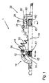
- the single figure of the application illustrates a constant velocity joint shaft 1 according to the invention for a motor vehicle.
- the constant velocity universal joint 1 has, on the outside, a constant velocity joint 10, which comprises an outer spherical shell 12 and an inner spherical star 14. Between ball shell 12 and ball star 14 a plurality of bearing balls 16 is arranged, which are trapped in a ball cage 18. On the outside, the constant velocity joint 10 is provided with external teeth for connection to the suspension of a (steered) drive wheel.
- the construction of the constant velocity joint corresponds to that of the previously known from the prior art constant velocity joints.
- the inside end of the constant velocity universal joint shaft 1 according to the invention is formed by a sliding joint 20, which has a tulip 22.
- a sliding joint 20 which has a tulip 22.
- a Tripodestern 26 is arranged, which in turn forms a plurality of bearing pin 28, wherein each track 24 of the tulip 22 is associated with a pin 28 of the Tripodesterns 26.
- Each journal 28 carries a rolling bearing 30, which is inserted with its outer ring in a raceway 24. In this case, the rolling bearing 30 in the receiving track 24 is displaceable in the axial direction.
- the bearing pin 28 and the inner rings of the rolling bearing 30 are designed so that the rolling bearings 30 can perform a tilting movement against the longitudinal axis of the bearing pin 28.
- various suitable constructions are already known from the prior art.
- a spherical configuration of the journal 28 is here (in deviation from the FIG. 1 ), wherein the inner surface of the inner ring of the rolling bearing 30 is designed to be complementary, so that the rolling bearing 30 can perform a tilting movement on the bearing journal 28 carrying it.
- a corresponding construction is for example from the DE 103 25 116 which is also attributable to the assignee of the present application.
- the rolling bearings 30 are then designed so that the inner ring of the rolling bearing 30 can perform a tilting movement relative to the outer ring of the rolling bearing 30. Both embodiments are fundamentally suitable for use in the context of an inventive constant velocity universal joint shaft.
- the constant velocity universal joint comprises a connecting shaft 40 which is rotatably connected on the one hand with the ball star 14 of the constant velocity joint 10 and on the other hand, the Tripodestern 26 of Verschiebegelenks 20.
- the connecting shaft 40 has at its two ends on external teeth, which engage in complementary formed internal gears on the inner circumference of the ball star 14 of the constant velocity joint 10 and the Tripodesterns 26 of the sliding joint
- the seat of the ball star 14 is now formed on the outside end of the connecting shaft 40 in the axial direction as a sliding seat.
- an axial force of less than 500 kN, in particular less than 100 kN has to be expended. It is particularly preferred if the axial force required for displacing the ball star 14 is in the range of a few hundred Newton, in particular in the region of 100 N.
- Particularly suitable splines have proven to the realization of the sliding seat of the ball star 14 on the connecting shaft 10 involute.
- the constant velocity joint 10 has an angular play of 0.3 ° or less, it has been found that the NVH properties of the constant velocity universal joint 1 according to the invention are better, the less the angular clearance of the constant velocity joint 10.
- a constant velocity joint 10 is selected in the manufacture of the constant velocity universal joint 1 according to the invention, the angular play is within the specified limits.
- the connecting shaft 40 also forms a fitting toothing 42, which is received on the inner circumference of the tripod star 26 by a complementary toothing.
- a rotationally fixed connection between Tripodestern 26 and connecting shaft 40 is realized, which is virtually free of play, both in the axial direction and in the direction of rotation.
- a securing element 50 is provided at the inner end of the connecting shaft 40, which secures the Tripodestern 26 on the end of the connecting shaft 40.
- the securing element 50 may be formed, for example, as a securing ring, which engages in a running on the outer circumference of the connecting shaft 40 groove.
- a further improvement in the operational safety of the constant velocity universal joint shaft 1 according to the invention can be achieved, although the ball star 14 of the constant velocity joint 10 is secured on the outer end of the connecting shaft 40 by means of a suitable securing element 50, which in turn can be configured as a locking ring.
- NVH properties of the constant velocity universal joint according to the invention can also be further improved if the relative movement of the ball star 14 of the constant velocity joint 10 and the connecting shaft 40 by insertion of a damping element 50 zw ischen ball star 14 and connecting shaft 40 is attenuated.
- this damping element may consist of an elastomer and be arranged immediately adjacent to the arranged to secure the ball star 14 on the outer end of the connecting shaft 40 securing element 50.
- the sliding seat of the ball star 14 on the outer end of the connecting shaft 40 in the axial direction can be realized, for example, by forming ball studs 14 and connecting shaft 40 a spline with involute flanks whose dimensions are dimensioned so that without further processing of the splines a press fit of the ball star 14 the outer end of the connecting shaft 40 would result. Subsequently, then the external teeth of the outer end of the connecting shaft 40 or the internal toothing of the ball star 14 or both teeth of a treatment z. B. be subjected by sandblasting, resulting in a sliding seat in the sense of the present application.
- a method for producing a constant velocity joint shaft 1 with the properties according to the invention generally comprises the selection of Vemchiebegelenken 10 with an angular play, which is within the specified range. Moreover, it includes the selection of a connecting shaft 40 and a ball star 14, in which a sliding seat of the ball star 14 is realized with the specified properties. Again, a corresponding selection step will usually be carried out in the context of the method according to the invention.
Landscapes
- Engineering & Computer Science (AREA)
- General Engineering & Computer Science (AREA)
- Mechanical Engineering (AREA)
- Shafts, Cranks, Connecting Bars, And Related Bearings (AREA)
- Arrangement And Driving Of Transmission Devices (AREA)
- Testing Of Devices, Machine Parts, Or Other Structures Thereof (AREA)
Claims (20)
- Arbre à joint homocinétique (1) pour un véhicule automobile, présentant les caractéristiques suivantes :a. un joint homocinétique (10) comprenant une coque sphérique (12) située à l'extérieur et un croisillon sphérique (14) situé à l'intérieur,b. un joint coulissant (20) ayant une tulipe (22) formant une pluralité de chemins de roulement (24) s'étendant longitudinalement et répartis uniformément suivant la circonférence intérieure, ainsi qu'une étoile formant plusieurs tenons (28), à chacun des chemins de roulement (24) de ladite tulipe (22) étant associé un tenon (28) de ladite étoile, etc. un arbre de liaison (40) qui est solidaire en rotation :i. dudit croisillon sphérique (14) du joint homocinétique (10), la liaison solidaire en rotation entre ledit croisillon sphérique (14) et ledit arbre de liaison (40) formant un ajustement appuyé dans la direction axiale, etii. de ladite étoile du joint coulissant (20),caractérisé par le fait qued. la force axiale nécessaire à déplacer ledit croisillon sphérique (14) sur ledit arbre de liaison (40) est inférieure à 500 kN, de préférence inférieure à 100 kN, et quee. le jeu angulaire entre ledit arbre de liaison (40) et ladite tulipe du joint coulissant est compris entre 0,3° et 1,4°, et queladite étoile est une étoile tripode (26).
- Arbre à joint homocinétique (1) selon la revendication 1, caractérisé par le fait que la liaison solidaire en rotation entre ledit arbre de liaison (40) et ledit croisillon sphérique et/ou ledit arbre de liaison (40) et ladite étoile tripode (26) est réalisée sous forme d'une denture d'ajustement (42).
- Arbre à joint homocinétique (1) selon la revendication 1, caractérisé par le fait que le jeu angulaire entre ledit arbre de liaison (40) et ladite tulipe (22) du joint coulissant (20) est supérieur à 0,6°.
- Arbre à joint homocinétique (1) selon la revendication 2, caractérisé par le fait que ladite denture d'ajustement (42) entre ledit arbre de liaison (40) et ledit croisillon sphérique présente des flancs en développante.
- Arbre à joint homocinétique (1) selon la revendication 2, caractérisé par le fait que ladite denture d'ajustement (42) entre ledit arbre de liaison (40) et ledit croisillon sphérique (14) présente des flancs angulaires ou des flancs parallèles.
- Arbre à joint homocinétique (1) selon la revendication 1, caractérisé par le fait que le jeu angulaire entre ledit arbre de liaison (40) et la coque sphérique (12) du joint homocinétique (1) est inférieur à 0,6°, de préférence il fait 0,3° ou moins.
- Arbre à joint homocinétique (1) selon la revendication 1, caractérisé par le fait que le mouvement axial du croisillon sphérique (14) sur ledit arbre de liaison (40) est limité par un élément de sécurité (50).
- Arbre à joint homocinétique (1) selon la revendication 1, caractérisé par le fait que l'on prévoit un élément amortisseur (52) pour amortir le mouvement axial du croisillon sphérique (14) sur ledit arbre de liaison (40).
- Arbre à joint homocinétique (1) selon la revendication 1, caractérisé par le fait que le diamètre extérieur de l'arbre de liaison (40) fait au moins 35 % du diamètre extérieur du croisillon sphérique.
- Procédé de fabrication d'un arbre à joint homocinétique (1) pour un véhicule automobile, comprenant les étapes de procédé suivantes :a. fournir un joint homocinétique (10) comprenant une coque sphérique (12) située à l'extérieur et un croisillon sphérique (14) situé à l'intérieur,b. fournir un joint coulissant (20) ayant une tulipe (22) formant une pluralité de chemins de roulement (24) s'étendant longitudinalement et répartis uniformément suivant la circonférence intérieure, ainsi qu'une étoile tripode (26) formant plusieurs tenons (28), à chacun des chemins de roulement (24) de ladite tulipe (22) étant associé un tenon (28) de ladite étoile tripode (26), etc. fournir un arbre de liaison (40),d. réaliser une liaison solidaire en rotation entre ledit croisillon sphérique (14) et ledit arbre de liaison (40), la liaison solidaire en rotation formant un ajustement appuyé dans la direction axiale et la force axiale nécessaire à déplacer ledit croisillon sphérique (14) sur ledit arbre de liaison (40) étant inférieure à 500 kN, de préférence inférieure à 100 kN,e. réaliser une liaison solidaire en rotation entre ladite étoile tripode (26) et ledit arbre de liaison (40), le jeu angulaire entre ledit arbre de liaison (40) et ladite tulipe (22) du joint coulissant (20) étant compris entre 0,3° et 1,4°.
- Procédé selon la revendication 10, caractérisé par le fait que la liaison solidaire en rotation entre ladite étoile tripode (26) et l'arbre de liaison (40) est pour l'essentiel exempte de jeu dans la direction axiale et dans la direction de rotation.
- Procédé selon la revendication 10, caractérisé par le fait que l'ajustement appuyé du croisillon sphérique (14) sur l'arbre de liaison (40) est pour l'essentiel exempt de jeu dans la direction de rotation.
- Procédé selon la revendication 10, caractérisé par le fait que la liaison solidaire en rotation entre ledit arbre de liaison (40) et ledit croisillon sphérique (14) et/ou ledit arbre de liaison (40) et ladite étoile tripode (26) est réalisée comme denture d'ajustement.
- Procédé selon la revendication 10, caractérisé par le fait que le jeu angulaire entre ledit arbre de liaison (40) et ladite tulipe (22) du joint coulissant (20) est supérieur à 0,6°.
- Procédé selon la revendication 13, caractérisé par le fait que ladite denture d'ajustement (42) entre ledit arbre de liaison (40) et ledit croisillon sphérique (14) présente des flancs en développante.
- Procédé selon la revendication 13, caractérisé par le fait que ladite denture d'ajustement (42) entre ledit arbre de liaison (40) et ledit croisillon sphérique (14) présente des flancs angulaires ou des flancs parallèles.
- Procédé selon la revendication 10, caractérisé par le fait que le jeu angulaire entre ledit arbre de liaison (40) et la coque sphérique (12) du joint homocinétique (1) est inférieur à 0,6°, de préférence il fait 0,3° ou moins.
- Procédé selon la revendication 10, caractérisé par le fait que pour limiter le mouvement axial du croisillon sphérique (14) sur ledit arbre de liaison (40), un élément de sécurité (50) est disposé sur ledit arbre de liaison (40).
- Procédé selon la revendication 10, caractérisé par le fait que pour amortir le mouvement axial du croisillon sphérique sur ledit arbre de liaison, un élément amortisseur est disposé sur l'arbre de liaison.
- Procédé selon la revendication 10, caractérisé par le fait que le diamètre extérieur de l'arbre de liaison (40) fourni fait au moins 35 % du diamètre extérieur du croisillon sphérique (14).
Applications Claiming Priority (2)
| Application Number | Priority Date | Filing Date | Title |
|---|---|---|---|
| DE102007008057A DE102007008057A1 (de) | 2007-02-15 | 2007-02-15 | Gleichlaufgelenkwelle für ein Kfz |
| PCT/EP2008/051782 WO2008098983A1 (fr) | 2007-02-15 | 2008-02-14 | Arbre à joint homocinétique pour véhicule |
Publications (2)
| Publication Number | Publication Date |
|---|---|
| EP2122189A1 EP2122189A1 (fr) | 2009-11-25 |
| EP2122189B1 true EP2122189B1 (fr) | 2011-11-23 |
Family
ID=39362529
Family Applications (1)
| Application Number | Title | Priority Date | Filing Date |
|---|---|---|---|
| EP08708982A Active EP2122189B1 (fr) | 2007-02-15 | 2008-02-14 | Arbre a joint homocinetique pour vehicule |
Country Status (4)
| Country | Link |
|---|---|
| EP (1) | EP2122189B1 (fr) |
| AT (1) | ATE534835T1 (fr) |
| DE (1) | DE102007008057A1 (fr) |
| WO (1) | WO2008098983A1 (fr) |
Family Cites Families (5)
| Publication number | Priority date | Publication date | Assignee | Title |
|---|---|---|---|---|
| USRE30606E (en) * | 1978-11-13 | 1981-05-12 | Telescoping universal joints | |
| DE3128682A1 (de) * | 1981-07-21 | 1983-02-10 | Gelenkwellenbau Gmbh, 4300 Essen | "gelenkwelle" |
| DE10220836A1 (de) * | 2002-05-08 | 2004-04-15 | Girguis, Sobhy Labib, Dipl.-Ing. | Gleichlaufschiebegelenk |
| DE10325116A1 (de) | 2003-06-02 | 2005-01-13 | Visteon Global Technologies, Inc., Dearborn | Gleichlaufdrehgelenk |
| JP4584090B2 (ja) * | 2005-09-15 | 2010-11-17 | Ntn株式会社 | 複合型等速自在継手 |
-
2007
- 2007-02-15 DE DE102007008057A patent/DE102007008057A1/de not_active Withdrawn
-
2008
- 2008-02-14 WO PCT/EP2008/051782 patent/WO2008098983A1/fr not_active Ceased
- 2008-02-14 AT AT08708982T patent/ATE534835T1/de active
- 2008-02-14 EP EP08708982A patent/EP2122189B1/fr active Active
Also Published As
| Publication number | Publication date |
|---|---|
| EP2122189A1 (fr) | 2009-11-25 |
| ATE534835T1 (de) | 2011-12-15 |
| DE102007008057A1 (de) | 2008-08-21 |
| WO2008098983A1 (fr) | 2008-08-21 |
Similar Documents
| Publication | Publication Date | Title |
|---|---|---|
| DE3636243C2 (fr) | ||
| DE102007016427B4 (de) | Lageranordnung einer über ein Drehgelenk antreibbaren Radnabe eines Kraftfahrzeuges | |
| DE3239121C2 (de) | Lagerungsanordnung einer über ein Gleichlaufdrehgelenk antreibbaren Radnabe | |
| WO2008148373A1 (fr) | Dispositif de liaison solidaire en rotation d'un pivot d'une transmission, avec un corps articulé d'une articulation de transmission d'un arbre de commande | |
| DE19606858C2 (de) | Wellenkupplung | |
| EP1910100A1 (fr) | Systeme de palier de roue a denture droite | |
| DE4217414C2 (de) | Achslager, insbesondere Radachslager für Kraftfahrzeuge | |
| EP2427667A2 (fr) | Joint homocinétique et arbre de transmission | |
| DE102004008538B4 (de) | Differential mit einer Bolzenbefestigungsbaugruppe | |
| DE29616432U1 (de) | Gelenkwelle mit Verbindungswelle | |
| DE2721098A1 (de) | Universalgelenk | |
| EP3819136B1 (fr) | Unité de roulement de roue pour un véhicule à moteur et procédé de fabrication d'une unité de roulement de roue | |
| DE4022692A1 (de) | Verfahren zur herstellung einer antriebswelle mit einstueckig angeformten gelenkkomponenten | |
| DE4310008A1 (de) | Drehmomentübertragende Gelenkanbindung für Antriebswellen oder mehrteilige Kardanwellen von Kraftfahrzeugen | |
| EP2288818A1 (fr) | Joint tripode pour arbre à cardan d'un véhicule automobile et arbre à cardan | |
| DE102018216910A1 (de) | Übersetzungsgetriebe für ein Fahrzeug mit einer Elektromaschine | |
| EP2122189A1 (fr) | Arbre a joint homocinetique pour vehicule | |
| WO2013149774A1 (fr) | Ensemble moyeu de roue et joint rotatif | |
| DE102017219546A1 (de) | Zahnradanordnung | |
| DE202017101823U1 (de) | Tonnenkupplung, insbesondere für eine Seiltrommelgelenkverbindung eines Hubwerks | |
| DE3615858A1 (de) | Radantrieb fuer kraftfahrzeuge | |
| DE102021102412A1 (de) | Riemenscheibenentkoppler mit zweiteiliger Nabe sowie Herstellungsverfahren für Nabe | |
| WO2024179908A1 (fr) | Arbre d'entraînement | |
| DE102022121959A1 (de) | Verfahren zur Herstellung einer Gelenkwellenanordnung sowie eine Gelenkwellenanordnung | |
| DE102014018226A1 (de) | Gleichlaufgelenk für eine Gelenkwelle, insbesondere eines Antriebsstrangs eines Kraftwagens |
Legal Events
| Date | Code | Title | Description |
|---|---|---|---|
| PUAI | Public reference made under article 153(3) epc to a published international application that has entered the european phase |
Free format text: ORIGINAL CODE: 0009012 |
|
| 17P | Request for examination filed |
Effective date: 20090817 |
|
| AK | Designated contracting states |
Kind code of ref document: A1 Designated state(s): AT BE BG CH CY CZ DE DK EE ES FI FR GB GR HR HU IE IS IT LI LT LU LV MC MT NL NO PL PT RO SE SI SK TR |
|
| RIN1 | Information on inventor provided before grant (corrected) |
Inventor name: FELCHNER, CHRISTIAN Inventor name: SCHWAB, MARCO Inventor name: HOEKS, LUIS |
|
| DAX | Request for extension of the european patent (deleted) | ||
| 17Q | First examination report despatched |
Effective date: 20100727 |
|
| RIN1 | Information on inventor provided before grant (corrected) |
Inventor name: SCHWAB, MARCO Inventor name: FELCHNER, CHRISTIAN Inventor name: HOEKS, LUIS |
|
| RAP1 | Party data changed (applicant data changed or rights of an application transferred) |
Owner name: NEAPCO EUROPE GMBH |
|
| GRAP | Despatch of communication of intention to grant a patent |
Free format text: ORIGINAL CODE: EPIDOSNIGR1 |
|
| GRAS | Grant fee paid |
Free format text: ORIGINAL CODE: EPIDOSNIGR3 |
|
| GRAA | (expected) grant |
Free format text: ORIGINAL CODE: 0009210 |
|
| AK | Designated contracting states |
Kind code of ref document: B1 Designated state(s): AT BE BG CH CY CZ DE DK EE ES FI FR GB GR HR HU IE IS IT LI LT LU LV MC MT NL NO PL PT RO SE SI SK TR |
|
| REG | Reference to a national code |
Ref country code: GB Ref legal event code: FG4D Free format text: NOT ENGLISH |
|
| REG | Reference to a national code |
Ref country code: CH Ref legal event code: EP |
|
| REG | Reference to a national code |
Ref country code: IE Ref legal event code: FG4D Free format text: LANGUAGE OF EP DOCUMENT: GERMAN |
|
| REG | Reference to a national code |
Ref country code: NL Ref legal event code: VDEP Effective date: 20111123 |
|
| REG | Reference to a national code |
Ref country code: DE Ref legal event code: R096 Ref document number: 502008005666 Country of ref document: DE Effective date: 20120308 |
|
| LTIE | Lt: invalidation of european patent or patent extension |
Effective date: 20111123 |
|
| PG25 | Lapsed in a contracting state [announced via postgrant information from national office to epo] |
Ref country code: LT Free format text: LAPSE BECAUSE OF FAILURE TO SUBMIT A TRANSLATION OF THE DESCRIPTION OR TO PAY THE FEE WITHIN THE PRESCRIBED TIME-LIMIT Effective date: 20111123 Ref country code: IS Free format text: LAPSE BECAUSE OF FAILURE TO SUBMIT A TRANSLATION OF THE DESCRIPTION OR TO PAY THE FEE WITHIN THE PRESCRIBED TIME-LIMIT Effective date: 20120323 Ref country code: NO Free format text: LAPSE BECAUSE OF FAILURE TO SUBMIT A TRANSLATION OF THE DESCRIPTION OR TO PAY THE FEE WITHIN THE PRESCRIBED TIME-LIMIT Effective date: 20120223 |
|
| PGFP | Annual fee paid to national office [announced via postgrant information from national office to epo] |
Ref country code: FR Payment date: 20120403 Year of fee payment: 5 |
|
| PG25 | Lapsed in a contracting state [announced via postgrant information from national office to epo] |
Ref country code: NL Free format text: LAPSE BECAUSE OF FAILURE TO SUBMIT A TRANSLATION OF THE DESCRIPTION OR TO PAY THE FEE WITHIN THE PRESCRIBED TIME-LIMIT Effective date: 20111123 Ref country code: LV Free format text: LAPSE BECAUSE OF FAILURE TO SUBMIT A TRANSLATION OF THE DESCRIPTION OR TO PAY THE FEE WITHIN THE PRESCRIBED TIME-LIMIT Effective date: 20111123 Ref country code: GR Free format text: LAPSE BECAUSE OF FAILURE TO SUBMIT A TRANSLATION OF THE DESCRIPTION OR TO PAY THE FEE WITHIN THE PRESCRIBED TIME-LIMIT Effective date: 20120224 Ref country code: HR Free format text: LAPSE BECAUSE OF FAILURE TO SUBMIT A TRANSLATION OF THE DESCRIPTION OR TO PAY THE FEE WITHIN THE PRESCRIBED TIME-LIMIT Effective date: 20111123 Ref country code: SE Free format text: LAPSE BECAUSE OF FAILURE TO SUBMIT A TRANSLATION OF THE DESCRIPTION OR TO PAY THE FEE WITHIN THE PRESCRIBED TIME-LIMIT Effective date: 20111123 Ref country code: SI Free format text: LAPSE BECAUSE OF FAILURE TO SUBMIT A TRANSLATION OF THE DESCRIPTION OR TO PAY THE FEE WITHIN THE PRESCRIBED TIME-LIMIT Effective date: 20111123 Ref country code: PT Free format text: LAPSE BECAUSE OF FAILURE TO SUBMIT A TRANSLATION OF THE DESCRIPTION OR TO PAY THE FEE WITHIN THE PRESCRIBED TIME-LIMIT Effective date: 20120323 |
|
| REG | Reference to a national code |
Ref country code: IE Ref legal event code: FD4D |
|
| PG25 | Lapsed in a contracting state [announced via postgrant information from national office to epo] |
Ref country code: CY Free format text: LAPSE BECAUSE OF FAILURE TO SUBMIT A TRANSLATION OF THE DESCRIPTION OR TO PAY THE FEE WITHIN THE PRESCRIBED TIME-LIMIT Effective date: 20111123 |
|
| PGFP | Annual fee paid to national office [announced via postgrant information from national office to epo] |
Ref country code: GB Payment date: 20120322 Year of fee payment: 5 |
|
| PG25 | Lapsed in a contracting state [announced via postgrant information from national office to epo] |
Ref country code: IE Free format text: LAPSE BECAUSE OF FAILURE TO SUBMIT A TRANSLATION OF THE DESCRIPTION OR TO PAY THE FEE WITHIN THE PRESCRIBED TIME-LIMIT Effective date: 20111123 Ref country code: DK Free format text: LAPSE BECAUSE OF FAILURE TO SUBMIT A TRANSLATION OF THE DESCRIPTION OR TO PAY THE FEE WITHIN THE PRESCRIBED TIME-LIMIT Effective date: 20111123 Ref country code: CZ Free format text: LAPSE BECAUSE OF FAILURE TO SUBMIT A TRANSLATION OF THE DESCRIPTION OR TO PAY THE FEE WITHIN THE PRESCRIBED TIME-LIMIT Effective date: 20111123 Ref country code: SK Free format text: LAPSE BECAUSE OF FAILURE TO SUBMIT A TRANSLATION OF THE DESCRIPTION OR TO PAY THE FEE WITHIN THE PRESCRIBED TIME-LIMIT Effective date: 20111123 Ref country code: EE Free format text: LAPSE BECAUSE OF FAILURE TO SUBMIT A TRANSLATION OF THE DESCRIPTION OR TO PAY THE FEE WITHIN THE PRESCRIBED TIME-LIMIT Effective date: 20111123 Ref country code: BG Free format text: LAPSE BECAUSE OF FAILURE TO SUBMIT A TRANSLATION OF THE DESCRIPTION OR TO PAY THE FEE WITHIN THE PRESCRIBED TIME-LIMIT Effective date: 20120223 |
|
| BERE | Be: lapsed |
Owner name: NEAPCO EUROPE G.M.B.H. Effective date: 20120228 |
|
| PG25 | Lapsed in a contracting state [announced via postgrant information from national office to epo] |
Ref country code: IT Free format text: LAPSE BECAUSE OF FAILURE TO SUBMIT A TRANSLATION OF THE DESCRIPTION OR TO PAY THE FEE WITHIN THE PRESCRIBED TIME-LIMIT Effective date: 20111123 Ref country code: RO Free format text: LAPSE BECAUSE OF FAILURE TO SUBMIT A TRANSLATION OF THE DESCRIPTION OR TO PAY THE FEE WITHIN THE PRESCRIBED TIME-LIMIT Effective date: 20111123 Ref country code: PL Free format text: LAPSE BECAUSE OF FAILURE TO SUBMIT A TRANSLATION OF THE DESCRIPTION OR TO PAY THE FEE WITHIN THE PRESCRIBED TIME-LIMIT Effective date: 20111123 |
|
| PG25 | Lapsed in a contracting state [announced via postgrant information from national office to epo] |
Ref country code: MC Free format text: LAPSE BECAUSE OF NON-PAYMENT OF DUE FEES Effective date: 20120229 |
|
| PLBE | No opposition filed within time limit |
Free format text: ORIGINAL CODE: 0009261 |
|
| REG | Reference to a national code |
Ref country code: CH Ref legal event code: PL |
|
| STAA | Information on the status of an ep patent application or granted ep patent |
Free format text: STATUS: NO OPPOSITION FILED WITHIN TIME LIMIT |
|
| 26N | No opposition filed |
Effective date: 20120824 |
|
| PG25 | Lapsed in a contracting state [announced via postgrant information from national office to epo] |
Ref country code: LI Free format text: LAPSE BECAUSE OF NON-PAYMENT OF DUE FEES Effective date: 20120229 Ref country code: CH Free format text: LAPSE BECAUSE OF NON-PAYMENT OF DUE FEES Effective date: 20120229 |
|
| REG | Reference to a national code |
Ref country code: DE Ref legal event code: R097 Ref document number: 502008005666 Country of ref document: DE Effective date: 20120824 |
|
| PG25 | Lapsed in a contracting state [announced via postgrant information from national office to epo] |
Ref country code: BE Free format text: LAPSE BECAUSE OF NON-PAYMENT OF DUE FEES Effective date: 20120228 |
|
| PG25 | Lapsed in a contracting state [announced via postgrant information from national office to epo] |
Ref country code: ES Free format text: LAPSE BECAUSE OF FAILURE TO SUBMIT A TRANSLATION OF THE DESCRIPTION OR TO PAY THE FEE WITHIN THE PRESCRIBED TIME-LIMIT Effective date: 20120305 |
|
| PG25 | Lapsed in a contracting state [announced via postgrant information from national office to epo] |
Ref country code: FI Free format text: LAPSE BECAUSE OF FAILURE TO SUBMIT A TRANSLATION OF THE DESCRIPTION OR TO PAY THE FEE WITHIN THE PRESCRIBED TIME-LIMIT Effective date: 20111123 |
|
| PG25 | Lapsed in a contracting state [announced via postgrant information from national office to epo] |
Ref country code: MT Free format text: LAPSE BECAUSE OF FAILURE TO SUBMIT A TRANSLATION OF THE DESCRIPTION OR TO PAY THE FEE WITHIN THE PRESCRIBED TIME-LIMIT Effective date: 20111123 |
|
| GBPC | Gb: european patent ceased through non-payment of renewal fee |
Effective date: 20130214 |
|
| REG | Reference to a national code |
Ref country code: FR Ref legal event code: ST Effective date: 20131031 |
|
| PG25 | Lapsed in a contracting state [announced via postgrant information from national office to epo] |
Ref country code: GB Free format text: LAPSE BECAUSE OF NON-PAYMENT OF DUE FEES Effective date: 20130214 Ref country code: FR Free format text: LAPSE BECAUSE OF NON-PAYMENT OF DUE FEES Effective date: 20130228 |
|
| REG | Reference to a national code |
Ref country code: AT Ref legal event code: MM01 Ref document number: 534835 Country of ref document: AT Kind code of ref document: T Effective date: 20130214 |
|
| PG25 | Lapsed in a contracting state [announced via postgrant information from national office to epo] |
Ref country code: TR Free format text: LAPSE BECAUSE OF FAILURE TO SUBMIT A TRANSLATION OF THE DESCRIPTION OR TO PAY THE FEE WITHIN THE PRESCRIBED TIME-LIMIT Effective date: 20111123 |
|
| PG25 | Lapsed in a contracting state [announced via postgrant information from national office to epo] |
Ref country code: LU Free format text: LAPSE BECAUSE OF NON-PAYMENT OF DUE FEES Effective date: 20120214 Ref country code: AT Free format text: LAPSE BECAUSE OF NON-PAYMENT OF DUE FEES Effective date: 20130214 |
|
| PG25 | Lapsed in a contracting state [announced via postgrant information from national office to epo] |
Ref country code: HU Free format text: LAPSE BECAUSE OF FAILURE TO SUBMIT A TRANSLATION OF THE DESCRIPTION OR TO PAY THE FEE WITHIN THE PRESCRIBED TIME-LIMIT Effective date: 20080214 |
|
| REG | Reference to a national code |
Ref country code: DE Ref legal event code: R082 Ref document number: 502008005666 Country of ref document: DE Representative=s name: LOHMANNS, BERNARD, DIPL.-PHYS., DE |
|
| PGFP | Annual fee paid to national office [announced via postgrant information from national office to epo] |
Ref country code: DE Payment date: 20260224 Year of fee payment: 19 |