EP2123193A1 - Schienenanordnung - Google Patents
Schienenanordnung Download PDFInfo
- Publication number
- EP2123193A1 EP2123193A1 EP09151398A EP09151398A EP2123193A1 EP 2123193 A1 EP2123193 A1 EP 2123193A1 EP 09151398 A EP09151398 A EP 09151398A EP 09151398 A EP09151398 A EP 09151398A EP 2123193 A1 EP2123193 A1 EP 2123193A1
- Authority
- EP
- European Patent Office
- Prior art keywords
- slide rail
- retaining
- mounting mechanism
- retaining member
- intermediate member
- Prior art date
- Legal status (The legal status is an assumption and is not a legal conclusion. Google has not performed a legal analysis and makes no representation as to the accuracy of the status listed.)
- Granted
Links
- 230000008878 coupling Effects 0.000 description 2
- 238000010168 coupling process Methods 0.000 description 2
- 238000005859 coupling reaction Methods 0.000 description 2
- 230000000717 retained effect Effects 0.000 description 2
- 230000000712 assembly Effects 0.000 description 1
- 238000000429 assembly Methods 0.000 description 1
- 238000000034 method Methods 0.000 description 1
- 230000003014 reinforcing effect Effects 0.000 description 1
Images


Classifications
-
- A—HUMAN NECESSITIES
- A47—FURNITURE; DOMESTIC ARTICLES OR APPLIANCES; COFFEE MILLS; SPICE MILLS; SUCTION CLEANERS IN GENERAL
- A47B—TABLES; DESKS; OFFICE FURNITURE; CABINETS; DRAWERS; GENERAL DETAILS OF FURNITURE
- A47B88/00—Drawers for tables, cabinets or like furniture; Guides for drawers
- A47B88/40—Sliding drawers; Slides or guides therefor
- A47B88/423—Fastening devices for slides or guides
- A47B88/43—Fastening devices for slides or guides at cabinet side
-
- H—ELECTRICITY
- H05—ELECTRIC TECHNIQUES NOT OTHERWISE PROVIDED FOR
- H05K—PRINTED CIRCUITS; CASINGS OR CONSTRUCTIONAL DETAILS OF ELECTRIC APPARATUS; MANUFACTURE OF ASSEMBLAGES OF ELECTRICAL COMPONENTS
- H05K7/00—Constructional details common to different types of electric apparatus
- H05K7/14—Mounting supporting structure in casing or on frame or rack
- H05K7/1485—Servers; Data center rooms, e.g. 19-inch computer racks
- H05K7/1488—Cabinets therefor, e.g. chassis or racks or mechanical interfaces between blades and support structures
- H05K7/1489—Cabinets therefor, e.g. chassis or racks or mechanical interfaces between blades and support structures characterized by the mounting of blades therein, e.g. brackets, rails, trays
Definitions
- the present invention relates to slide rail assemblies, and more particularly to a slide rail assembly including a mounting mechanism and a slide rail capable of being retained to a chassis with the mounting mechanism.
- a typical slide rail assembly for a server chassis and a rack includes an outer slide rail mounted to the rack, an inner slide rail mounted to the chassis, and an intermediate slide rail mounted between the outer and inner slide rails.
- the intermediate slide rail is extendable relative to the outer slide rail
- the inner slide rail is extendable relative to the intermediate slide rail, thus the chassis can be extended a distance out from the rack.
- the inner rail is secured to a side of the chassis with a plurality of screws. Therefore, a tool such as a screwdriver is needed for installing and detaching the slide rail, and the processes are tedious and time consuming.
- FIG. 1 is an exploded, isometric view of a mounting mechanism according to an embodiment of the present invention
- FIG. 2 is similar to FIG. 1 , but shown from another aspect
- FIG. 3 is an assembled view of the mounting mechanism of FIG.1 ;
- FIG. 4 is another assembled view of the mounting mechanism of FIG.1 ;
- FIG. 5 is a sectional view of FIG. 4 taken along the line V-V;
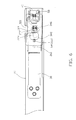
- FIG. 6 is a lateral view of FIG. 3 ;
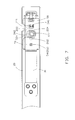
- FIG. 7 is a lateral view of FIG. 4 .
- a mounting mechanism in an embodiment of the present invention is provided for mounting a slide rail 20 to a chassis 10.
- the mounting mechanism includes a retaining member 30 coupled to the slide rail 20, a releasing member 40 rotatably coupled to the retaining member 30, and an intermediate member 50 slidably attached to the slide rail 20.
- the chassis 10 includes an anchor member 12 extending from a sidewall thereof.
- the anchor member 12 is a mushroom-shaped post, and includes a cap 122 and a shank 124 with a diameter smaller than that of the cap 122.
- the slide rail 20 includes a pair of flanges 21 extending from opposite edges towards the same direction.
- a mounting slot 22 is defined in the slide rail 20.
- the mounting slot 22 includes an accessing portion 222 and a fixing portion 224 communicating with the accessing portion 222.
- a plurality of protrusions 27 extends from the slide rail 20.
- Two positioning holes 261 and 262 are defined in the slide rail 20 and arranged along a longitudinal direction of the slide rail 20. The positioning hole 262 is located closer to the mounting slot 22 than to the positioning hole 261.
- the retaining member 30 is a resilient plate and includes a mounting portion 32 and a locking portion 34 extending from an end of the mounting portion 32.
- a plurality of coupling holes 322 is defined in a far end of the mounting portion 32 relative to the locking portion 34.
- Two flanges extend from opposite side edges of the locking portion 34 for reinforcing the locking portion 34.
- a pivoting portion 344 which includes a pair of offset hollowed cylinders, is formed on a far end of the locking portion 34 relative to the mounting portion 32.
- a notch 347 is defined in the locking portion 34 adjacent to the pivoting portion 344.
- the locking portion 34 also includes an interference avoiding hole 342 defined in the middle thereof, and a tab 346 formed thereon between the interference avoiding hole 342 and the notch 347.
- the releasing member 40 is generally B-shaped, and includes a pivoting shaft 42, an operating portion 44, and a resisting portion 46 disposed at opposite sides of the pivoting shaft 42.
- the resisting portion 46 includes a resisting pole 464, and a first arm 462 and a second arm 466 perpendicularly extending from opposite ends of the resisting pole 464.
- the second arm 466 connects to the operating portion 44 and is slightly bent, and therefore the operating portion 44, the pivoting shaft 42 and the resisting portion 46 are un-coplanar.
- the intermediate member 50 is a planar sheet.
- a substantially V-shaped cutout 52 is defined in the intermediate member 50 near a side edge.
- the cutout 52 includes a gateway 522 and a receiving portion 524 communicating with the gateway 522.
- the intermediate member 50 includes a cone-shaped locating portion 54 protruding therefrom and a retaining hole 56 defined therein.
- the locating portion 54 and the retaining hole 56 are arranged at opposite sides of the cutout 52, respectively.
- a bulge 58 is formed from an edge of the intermediate member 50 near the retaining hole 56.
- the intermediate member 50 abuts against the slide rail 20 and is slidably restricted between the two flanges 21.
- the locating portion 54 engages with the positioning hole 262 of the slide rail 20.
- the gateway 522 of cutout 52 is aligned with the accessing portion 222 of the mounting slot 22.
- the shaft 42 of the releasing member 40 passes through the pivoting portion 32 of the retaining member 30.
- the protrusions 27 of the slide rail 20 are correspondingly fixed in the coupling holes 34 of the retaining member 30 to attach the mounting portion 32 to the slide rail 20.
- the mounting portion 32 and the locking portion 34 of the retaining member 30 respectively abut against the slide rail 20 and the intermediate member 50.
- the tab 346 just extends into the cutout 52 of the intermediate member 50 and the mounting slot 22 of the slide rail 20.
- the operating portion 44 of the releasing member 40 engages with the retaining member 30 and is aligned with the notch 347.
- the resisting pole 464 of the releasing member 40 engages with the slide rail 20.
- the chassis 10 is moved to fit the shank 124 of the anchor member 12 into the mounting slot 22.
- the anchor member 12 slides down along the accessing portion 222 of the mounting slot 22, then slides leftward (shown in FIG. 6 ) along the fixing portion 224 of the mounting slot 22.
- the cap 122 of the anchor member 12 engages with the retaining member 30 and urges the locking portion 34 of the retaining member 30 to move away from the slide rail 20.
- the retaining member 30 is restored.
- the shank 124 of the anchor member 12 engages with a left rim of the cutout 52 of the intermediate member 50 to cause the intermediate member 50 to slide leftwards.
- the locating portion 54 disengages from the positioning hole 262 and slides to engage with the positioning hole 261.
- the tab 346 of the retaining member 30 extends into the retaining hole 56 to prevent the intermediate member 50 from sliding. Therefore, the shank 124 of the anchor member 12 is retained in the fixing portion 224 of the mounting slot 22.
- the slide rail 20 is secured to the chassis 10.
- a finger is extended to the notch 347 to manipulate the operating portion 44 of the releasing member 40 to move away from the retaining member 30. Therefore, the releasing member 40 is pivoted about the shaft 42 to resist the resisting pole 464 against the slide rail 20.
- the locking portion 34 of the retaining member 30 is raised from the slide rail 20.
- the tab 346 of the retaining member 30 disengages from the retaining hole 56 of the intermediate member 50.
- the releasing member 50 is pivoted until the first arm 462 and the second arm 466 slantingly engage with the end edge of the retaining member 30. Now, the intermediate member 50 is allowed to slide relative to the slide rail 20.
- the chassis 10 is moved to slide the shank 124 of the anchor member 12 rightward (shown in FIG. 7 ) along the fixing portion 224 of the mounting slot 22.
- the intermediate member 50 is urged to slide rightward by the shank 124 of the anchor member 12.
- the locating portion 54 disengages from the positioning hole 261 and slides to engage with the positioning hole 261.
- the shank 124 of the anchor member 12 slides up along the accessing portion 222 of the mounting slot 22 to exit from the mounting slot.22.
- the slide rail 20 is detached from the chassis 20.
- the locking portion 34 of the retaining member 30 should be restored. Otherwise, another rail (such as an intermediate slide rail) may interfere with and damage the retaining member 30 when the slide rail 20 slides therein.
- another rail such as an intermediate slide rail
- the bulge 58 engages with the resisting pole 464 of the releasing member 40.
- the releasing member 40 is urged to pivot to disengage the first arm 462 and the second arm 466 from the end edge of the retain member 30, so that the retaining member 30 is restored as long as the slide rail 20 is detached from the chassis 10.
Landscapes
- Engineering & Computer Science (AREA)
- Computer Hardware Design (AREA)
- General Engineering & Computer Science (AREA)
- Microelectronics & Electronic Packaging (AREA)
- Drawers Of Furniture (AREA)
- Moving Of Heads (AREA)
- Insulated Conductors (AREA)
- Seats For Vehicles (AREA)
Applications Claiming Priority (1)
| Application Number | Priority Date | Filing Date | Title |
|---|---|---|---|
| CN2008103017598A CN101587368B (zh) | 2008-05-23 | 2008-05-23 | 滑轨装置 |
Publications (2)
| Publication Number | Publication Date |
|---|---|
| EP2123193A1 true EP2123193A1 (de) | 2009-11-25 |
| EP2123193B1 EP2123193B1 (de) | 2011-01-05 |
Family
ID=41064596
Family Applications (1)
| Application Number | Title | Priority Date | Filing Date |
|---|---|---|---|
| EP09151398A Not-in-force EP2123193B1 (de) | 2008-05-23 | 2009-01-27 | Schienenanordnung |
Country Status (6)
| Country | Link |
|---|---|
| US (1) | US7871139B2 (de) |
| EP (1) | EP2123193B1 (de) |
| JP (1) | JP5363189B2 (de) |
| CN (1) | CN101587368B (de) |
| AT (1) | ATE493909T1 (de) |
| DE (1) | DE602009000517D1 (de) |
Cited By (3)
| Publication number | Priority date | Publication date | Assignee | Title |
|---|---|---|---|---|
| EP2417873A1 (de) * | 2010-08-09 | 2012-02-15 | King Slide Works Co., Ltd. | Schiebeanordnung |
| EP2550899A1 (de) * | 2011-07-27 | 2013-01-30 | King Slide Works Co., Ltd. | Installationsvorrichtung für eine Schiebeanordnung |
| CN106820680A (zh) * | 2015-12-03 | 2017-06-13 | 川湖科技股份有限公司 | 快拆式滑轨组件 |
Families Citing this family (22)
| Publication number | Priority date | Publication date | Assignee | Title |
|---|---|---|---|---|
| CN101522007B (zh) * | 2008-02-29 | 2012-12-19 | 鸿富锦精密工业(深圳)有限公司 | 滑轨固定装置 |
| US8162416B2 (en) * | 2008-12-15 | 2012-04-24 | Bush Industries, Inc. | Anti-tip system for adjacent drawers |
| CN101854789B (zh) * | 2010-04-23 | 2013-04-03 | 雅固拉国际精密工业(苏州)有限公司 | 一种用于服务器机箱的锁定装置 |
| CN102378541B (zh) * | 2010-08-20 | 2014-06-11 | 川湖科技股份有限公司 | 具有快速安装构造的滑轨总成 |
| US20120063709A1 (en) * | 2010-09-10 | 2012-03-15 | King Slide Works Co., Ltd. | Slide assembly |
| EP2446779B1 (de) * | 2010-11-02 | 2013-07-24 | King Slide Works Co., Ltd. | Schnellkupplung von Laufschiene |
| US8622492B2 (en) | 2011-06-17 | 2014-01-07 | King Slide Works Co., Ltd. | Positioning mechanism for quick release device of slide assembly |
| US8562085B2 (en) | 2011-08-08 | 2013-10-22 | King Slide Works Co. Ltd. | Installation device for slide assembly |
| CN103185069B (zh) * | 2011-12-27 | 2015-05-20 | 川湖科技股份有限公司 | 托架与滑轨的支撑构造 |
| US8366217B1 (en) * | 2012-01-23 | 2013-02-05 | King Slide Works Co., Ltd. | Installation device for slide assembly |
| US9642279B2 (en) * | 2015-03-12 | 2017-05-02 | King Slide Works Co., Ltd. | Rail mounting structure |
| US10015902B2 (en) * | 2015-08-28 | 2018-07-03 | Quanta Computer Inc. | Integrated moveable and lockable rail |
| TWI548369B (zh) * | 2015-10-06 | 2016-09-11 | King Slide Works Co Ltd | 用於滑軌總成的安裝配件 |
| TWI568381B (zh) * | 2015-12-21 | 2017-02-01 | 川湖科技股份有限公司 | 滑軌總成及其導引機構 |
| TWI594711B (zh) * | 2016-05-31 | 2017-08-11 | 川湖科技股份有限公司 | 滑軌裝置 |
| TWI600394B (zh) | 2016-07-19 | 2017-10-01 | 川湖科技股份有限公司 | 應用在機架系統的滑軌總成 |
| CN107684257B (zh) * | 2017-09-20 | 2024-07-26 | 东莞市帝格五金制品有限公司 | 一种用于抽屉的快装结构及抽屉 |
| TWI676099B (zh) * | 2017-11-01 | 2019-11-01 | 仁寶電腦工業股份有限公司 | 連動機構及電子裝置 |
| CN111142625B (zh) * | 2018-11-05 | 2021-08-24 | 纬联电子科技(中山)有限公司 | 固定架组与服务器 |
| CN109567447A (zh) * | 2018-11-09 | 2019-04-05 | 合肥全爱家居制造有限公司 | 一种具有缓冲功能可降噪的抽屉用滑轨 |
| CN113286475B (zh) * | 2020-02-19 | 2022-06-28 | 纬联电子科技(中山)有限公司 | 理线架与机箱 |
| CN118034464A (zh) * | 2022-11-14 | 2024-05-14 | 纬联电子科技(中山)有限公司 | 壳体组件与包括其的电子装置 |
Citations (4)
| Publication number | Priority date | Publication date | Assignee | Title |
|---|---|---|---|---|
| US5439284A (en) * | 1992-11-10 | 1995-08-08 | Grass Ag | Drawer with detachable connection of drawer casing and drawer rail |
| US20040174103A1 (en) * | 2003-03-07 | 2004-09-09 | Jun-Long Yang | Undetachable drawer rail |
| DE202006008564U1 (de) * | 2005-06-24 | 2006-08-24 | King Slide Works Co., Ltd., Lu-Chu Hsiang | Positionierung einer dreiteiligen Auszugschiene |
| US20070164644A1 (en) * | 2006-01-19 | 2007-07-19 | Shih-Long Hwang | Locating structure for a slide assembly |
Family Cites Families (15)
| Publication number | Priority date | Publication date | Assignee | Title |
|---|---|---|---|---|
| JPS5986148U (ja) * | 1982-12-02 | 1984-06-11 | 日本アキユライド株式会社 | スライドレ−ルにおける抽斗等の取付装置 |
| US6373707B1 (en) * | 2000-06-02 | 2002-04-16 | Astec International Limited | Module mounting slide clamp mechanism |
| US6588866B2 (en) * | 2001-04-27 | 2003-07-08 | Intel Corporation | Slide rail attachment |
| US6938967B2 (en) * | 2001-12-12 | 2005-09-06 | Pentair Electronic Packaging Co. | Telescoping slide assembly |
| CN2590455Y (zh) * | 2002-12-12 | 2003-12-10 | 川湖工厂股份有限公司 | 滑轨的固定结构 |
| US7364245B2 (en) * | 2002-12-18 | 2008-04-29 | Pentair Electronic Packaging Company | Lateral alignment device |
| US6979067B2 (en) * | 2003-05-30 | 2005-12-27 | Central Industrial Supply Company | Cam lock with torsion spring for a drawer slide |
| US7382623B2 (en) * | 2003-06-11 | 2008-06-03 | Dell Products L.P. | Method and system for coupling a chassis to a rail |
| GB2410678B (en) * | 2004-02-09 | 2007-01-31 | King Slide Works Co Ltd | Positioning device for a multi-section slide track assembly of drawers |
| TWI256295B (en) * | 2005-07-22 | 2006-06-11 | King Slide Works Co Ltd | Quick-mount mechanism for telescoping slide |
| US7481504B2 (en) * | 2005-11-23 | 2009-01-27 | King Slide Works Co., Ltd. | Mount latch structure for a telescoping slide |
| JP3119211U (ja) * | 2005-12-02 | 2006-02-16 | 川湖科技股▲分▼有限公司 | スライドレールの設置掛合構造 |
| CN100515276C (zh) * | 2006-06-23 | 2009-07-22 | 鸿富锦精密工业(深圳)有限公司 | 滑轨定位装置 |
| US7571968B2 (en) * | 2006-11-09 | 2009-08-11 | Central Industrial Supply Company | Front release lock with disconnect lock for a drawer slide |
| US7513581B1 (en) * | 2007-06-07 | 2009-04-07 | Central Industrial Supply Company | Chassis lock for a drawer slide |
-
2008
- 2008-05-23 CN CN2008103017598A patent/CN101587368B/zh not_active Expired - Fee Related
- 2008-09-01 US US12/202,328 patent/US7871139B2/en not_active Expired - Fee Related
-
2009
- 2009-01-27 EP EP09151398A patent/EP2123193B1/de not_active Not-in-force
- 2009-01-27 AT AT09151398T patent/ATE493909T1/de not_active IP Right Cessation
- 2009-01-27 DE DE602009000517T patent/DE602009000517D1/de active Active
- 2009-05-19 JP JP2009121073A patent/JP5363189B2/ja not_active Expired - Fee Related
Patent Citations (4)
| Publication number | Priority date | Publication date | Assignee | Title |
|---|---|---|---|---|
| US5439284A (en) * | 1992-11-10 | 1995-08-08 | Grass Ag | Drawer with detachable connection of drawer casing and drawer rail |
| US20040174103A1 (en) * | 2003-03-07 | 2004-09-09 | Jun-Long Yang | Undetachable drawer rail |
| DE202006008564U1 (de) * | 2005-06-24 | 2006-08-24 | King Slide Works Co., Ltd., Lu-Chu Hsiang | Positionierung einer dreiteiligen Auszugschiene |
| US20070164644A1 (en) * | 2006-01-19 | 2007-07-19 | Shih-Long Hwang | Locating structure for a slide assembly |
Cited By (4)
| Publication number | Priority date | Publication date | Assignee | Title |
|---|---|---|---|---|
| EP2417873A1 (de) * | 2010-08-09 | 2012-02-15 | King Slide Works Co., Ltd. | Schiebeanordnung |
| EP2550899A1 (de) * | 2011-07-27 | 2013-01-30 | King Slide Works Co., Ltd. | Installationsvorrichtung für eine Schiebeanordnung |
| CN106820680A (zh) * | 2015-12-03 | 2017-06-13 | 川湖科技股份有限公司 | 快拆式滑轨组件 |
| CN106820680B (zh) * | 2015-12-03 | 2018-11-09 | 川湖科技股份有限公司 | 快拆式滑轨组件 |
Also Published As
| Publication number | Publication date |
|---|---|
| CN101587368B (zh) | 2011-11-09 |
| DE602009000517D1 (de) | 2011-02-17 |
| ATE493909T1 (de) | 2011-01-15 |
| CN101587368A (zh) | 2009-11-25 |
| EP2123193B1 (de) | 2011-01-05 |
| US7871139B2 (en) | 2011-01-18 |
| JP5363189B2 (ja) | 2013-12-11 |
| JP2009279410A (ja) | 2009-12-03 |
| US20090289155A1 (en) | 2009-11-26 |
Similar Documents
| Publication | Publication Date | Title |
|---|---|---|
| US7871139B2 (en) | Slide rail assembly | |
| US8047620B2 (en) | Mounting mechanism for retaining a slide rail to a chassis | |
| US7864522B1 (en) | Hard disk drive holder | |
| US7848099B1 (en) | Hard disk drive holder | |
| US8403436B2 (en) | Slide rail assembly | |
| US8246129B2 (en) | Carrier | |
| US20090294621A1 (en) | Slide rail assembly | |
| US20090255099A1 (en) | Latch apparatus | |
| US8411429B2 (en) | Mounting apparatus for disk drive | |
| US10292496B2 (en) | Bracket device | |
| US20110017894A1 (en) | Mounting mechanism for retaining slide rail to chassis | |
| US8118377B2 (en) | Computer enclosure | |
| US8118267B2 (en) | Mounting mechanism for retaining slide rail to chassis | |
| US8641313B1 (en) | Latch for securing a compute node in a component storage rack | |
| US8154863B2 (en) | Data storage device assembly | |
| US7495909B1 (en) | Mounting device for data storage device | |
| EP3119171A1 (de) | Gleitschienenanordnung | |
| US20080303398A1 (en) | Slider assembly | |
| EP3451809B1 (de) | Klammervorrichtung | |
| US7108429B2 (en) | Releasing mechanism of an optical module from a host board | |
| US11744032B2 (en) | Carrying structure and server | |
| US20090213540A1 (en) | Fixing apparatus for functional module | |
| US8474769B2 (en) | Mounting apparatus for back panel | |
| US7447044B2 (en) | Fixing mechanism for printed circuit board | |
| US7447046B2 (en) | Mounting apparatus for drive bracket |
Legal Events
| Date | Code | Title | Description |
|---|---|---|---|
| PUAI | Public reference made under article 153(3) epc to a published international application that has entered the european phase |
Free format text: ORIGINAL CODE: 0009012 |
|
| AK | Designated contracting states |
Kind code of ref document: A1 Designated state(s): AT BE BG CH CY CZ DE DK EE ES FI FR GB GR HR HU IE IS IT LI LT LU LV MC MK MT NL NO PL PT RO SE SI SK TR |
|
| AX | Request for extension of the european patent |
Extension state: AL BA RS |
|
| GRAP | Despatch of communication of intention to grant a patent |
Free format text: ORIGINAL CODE: EPIDOSNIGR1 |
|
| 17P | Request for examination filed |
Effective date: 20100518 |
|
| AKX | Designation fees paid |
Designated state(s): AT BE BG CH CY CZ DE DK EE ES FI FR GB GR HR HU IE IS IT LI LT LU LV MC MK MT NL NO PL PT RO SE SI SK TR |
|
| GRAS | Grant fee paid |
Free format text: ORIGINAL CODE: EPIDOSNIGR3 |
|
| GRAA | (expected) grant |
Free format text: ORIGINAL CODE: 0009210 |
|
| RIN1 | Information on inventor provided before grant (corrected) |
Inventor name: ZHOU, HAI-CHENC/O HONG FU JIN PRECISION INDUSTRY Inventor name: YU, MO-MINGC/O HONG FU JIN PRECISION INDUSTRY |
|
| AK | Designated contracting states |
Kind code of ref document: B1 Designated state(s): AT BE BG CH CY CZ DE DK EE ES FI FR GB GR HR HU IE IS IT LI LT LU LV MC MK MT NL NO PL PT RO SE SI SK TR |
|
| REG | Reference to a national code |
Ref country code: GB Ref legal event code: FG4D |
|
| REG | Reference to a national code |
Ref country code: CH Ref legal event code: EP |
|
| REG | Reference to a national code |
Ref country code: IE Ref legal event code: FG4D |
|
| REF | Corresponds to: |
Ref document number: 602009000517 Country of ref document: DE Date of ref document: 20110217 Kind code of ref document: P |
|
| REG | Reference to a national code |
Ref country code: DE Ref legal event code: R096 Ref document number: 602009000517 Country of ref document: DE Effective date: 20110217 |
|
| REG | Reference to a national code |
Ref country code: NL Ref legal event code: VDEP Effective date: 20110105 |
|
| PG25 | Lapsed in a contracting state [announced via postgrant information from national office to epo] |
Ref country code: SI Free format text: LAPSE BECAUSE OF FAILURE TO SUBMIT A TRANSLATION OF THE DESCRIPTION OR TO PAY THE FEE WITHIN THE PRESCRIBED TIME-LIMIT Effective date: 20110105 |
|
| LTIE | Lt: invalidation of european patent or patent extension |
Effective date: 20110105 |
|
| PG25 | Lapsed in a contracting state [announced via postgrant information from national office to epo] |
Ref country code: ES Free format text: LAPSE BECAUSE OF FAILURE TO SUBMIT A TRANSLATION OF THE DESCRIPTION OR TO PAY THE FEE WITHIN THE PRESCRIBED TIME-LIMIT Effective date: 20110416 Ref country code: LV Free format text: LAPSE BECAUSE OF FAILURE TO SUBMIT A TRANSLATION OF THE DESCRIPTION OR TO PAY THE FEE WITHIN THE PRESCRIBED TIME-LIMIT Effective date: 20110105 Ref country code: SE Free format text: LAPSE BECAUSE OF FAILURE TO SUBMIT A TRANSLATION OF THE DESCRIPTION OR TO PAY THE FEE WITHIN THE PRESCRIBED TIME-LIMIT Effective date: 20110105 Ref country code: PT Free format text: LAPSE BECAUSE OF FAILURE TO SUBMIT A TRANSLATION OF THE DESCRIPTION OR TO PAY THE FEE WITHIN THE PRESCRIBED TIME-LIMIT Effective date: 20110505 Ref country code: LT Free format text: LAPSE BECAUSE OF FAILURE TO SUBMIT A TRANSLATION OF THE DESCRIPTION OR TO PAY THE FEE WITHIN THE PRESCRIBED TIME-LIMIT Effective date: 20110105 Ref country code: IS Free format text: LAPSE BECAUSE OF FAILURE TO SUBMIT A TRANSLATION OF THE DESCRIPTION OR TO PAY THE FEE WITHIN THE PRESCRIBED TIME-LIMIT Effective date: 20110505 Ref country code: NO Free format text: LAPSE BECAUSE OF FAILURE TO SUBMIT A TRANSLATION OF THE DESCRIPTION OR TO PAY THE FEE WITHIN THE PRESCRIBED TIME-LIMIT Effective date: 20110405 Ref country code: HR Free format text: LAPSE BECAUSE OF FAILURE TO SUBMIT A TRANSLATION OF THE DESCRIPTION OR TO PAY THE FEE WITHIN THE PRESCRIBED TIME-LIMIT Effective date: 20110105 Ref country code: GR Free format text: LAPSE BECAUSE OF FAILURE TO SUBMIT A TRANSLATION OF THE DESCRIPTION OR TO PAY THE FEE WITHIN THE PRESCRIBED TIME-LIMIT Effective date: 20110406 |
|
| PG25 | Lapsed in a contracting state [announced via postgrant information from national office to epo] |
Ref country code: PL Free format text: LAPSE BECAUSE OF FAILURE TO SUBMIT A TRANSLATION OF THE DESCRIPTION OR TO PAY THE FEE WITHIN THE PRESCRIBED TIME-LIMIT Effective date: 20110105 Ref country code: CY Free format text: LAPSE BECAUSE OF FAILURE TO SUBMIT A TRANSLATION OF THE DESCRIPTION OR TO PAY THE FEE WITHIN THE PRESCRIBED TIME-LIMIT Effective date: 20110105 Ref country code: FI Free format text: LAPSE BECAUSE OF FAILURE TO SUBMIT A TRANSLATION OF THE DESCRIPTION OR TO PAY THE FEE WITHIN THE PRESCRIBED TIME-LIMIT Effective date: 20110105 Ref country code: AT Free format text: LAPSE BECAUSE OF FAILURE TO SUBMIT A TRANSLATION OF THE DESCRIPTION OR TO PAY THE FEE WITHIN THE PRESCRIBED TIME-LIMIT Effective date: 20110105 Ref country code: MC Free format text: LAPSE BECAUSE OF NON-PAYMENT OF DUE FEES Effective date: 20110131 Ref country code: BG Free format text: LAPSE BECAUSE OF FAILURE TO SUBMIT A TRANSLATION OF THE DESCRIPTION OR TO PAY THE FEE WITHIN THE PRESCRIBED TIME-LIMIT Effective date: 20110405 Ref country code: BE Free format text: LAPSE BECAUSE OF FAILURE TO SUBMIT A TRANSLATION OF THE DESCRIPTION OR TO PAY THE FEE WITHIN THE PRESCRIBED TIME-LIMIT Effective date: 20110105 Ref country code: NL Free format text: LAPSE BECAUSE OF FAILURE TO SUBMIT A TRANSLATION OF THE DESCRIPTION OR TO PAY THE FEE WITHIN THE PRESCRIBED TIME-LIMIT Effective date: 20110105 |
|
| REG | Reference to a national code |
Ref country code: IE Ref legal event code: MM4A |
|
| PG25 | Lapsed in a contracting state [announced via postgrant information from national office to epo] |
Ref country code: EE Free format text: LAPSE BECAUSE OF FAILURE TO SUBMIT A TRANSLATION OF THE DESCRIPTION OR TO PAY THE FEE WITHIN THE PRESCRIBED TIME-LIMIT Effective date: 20110105 Ref country code: DK Free format text: LAPSE BECAUSE OF FAILURE TO SUBMIT A TRANSLATION OF THE DESCRIPTION OR TO PAY THE FEE WITHIN THE PRESCRIBED TIME-LIMIT Effective date: 20110105 |
|
| PLBE | No opposition filed within time limit |
Free format text: ORIGINAL CODE: 0009261 |
|
| STAA | Information on the status of an ep patent application or granted ep patent |
Free format text: STATUS: NO OPPOSITION FILED WITHIN TIME LIMIT |
|
| PG25 | Lapsed in a contracting state [announced via postgrant information from national office to epo] |
Ref country code: CZ Free format text: LAPSE BECAUSE OF FAILURE TO SUBMIT A TRANSLATION OF THE DESCRIPTION OR TO PAY THE FEE WITHIN THE PRESCRIBED TIME-LIMIT Effective date: 20110105 Ref country code: RO Free format text: LAPSE BECAUSE OF FAILURE TO SUBMIT A TRANSLATION OF THE DESCRIPTION OR TO PAY THE FEE WITHIN THE PRESCRIBED TIME-LIMIT Effective date: 20110105 Ref country code: SK Free format text: LAPSE BECAUSE OF FAILURE TO SUBMIT A TRANSLATION OF THE DESCRIPTION OR TO PAY THE FEE WITHIN THE PRESCRIBED TIME-LIMIT Effective date: 20110105 |
|
| 26N | No opposition filed |
Effective date: 20111006 |
|
| PG25 | Lapsed in a contracting state [announced via postgrant information from national office to epo] |
Ref country code: MT Free format text: LAPSE BECAUSE OF FAILURE TO SUBMIT A TRANSLATION OF THE DESCRIPTION OR TO PAY THE FEE WITHIN THE PRESCRIBED TIME-LIMIT Effective date: 20110105 Ref country code: IT Free format text: LAPSE BECAUSE OF FAILURE TO SUBMIT A TRANSLATION OF THE DESCRIPTION OR TO PAY THE FEE WITHIN THE PRESCRIBED TIME-LIMIT Effective date: 20110105 |
|
| PG25 | Lapsed in a contracting state [announced via postgrant information from national office to epo] |
Ref country code: IE Free format text: LAPSE BECAUSE OF NON-PAYMENT OF DUE FEES Effective date: 20110127 |
|
| REG | Reference to a national code |
Ref country code: DE Ref legal event code: R097 Ref document number: 602009000517 Country of ref document: DE Effective date: 20111006 |
|
| PG25 | Lapsed in a contracting state [announced via postgrant information from national office to epo] |
Ref country code: MK Free format text: LAPSE BECAUSE OF FAILURE TO SUBMIT A TRANSLATION OF THE DESCRIPTION OR TO PAY THE FEE WITHIN THE PRESCRIBED TIME-LIMIT Effective date: 20110105 |
|
| PGFP | Annual fee paid to national office [announced via postgrant information from national office to epo] |
Ref country code: DE Payment date: 20130122 Year of fee payment: 5 Ref country code: FR Payment date: 20130213 Year of fee payment: 5 Ref country code: GB Payment date: 20130111 Year of fee payment: 5 |
|
| PG25 | Lapsed in a contracting state [announced via postgrant information from national office to epo] |
Ref country code: LU Free format text: LAPSE BECAUSE OF NON-PAYMENT OF DUE FEES Effective date: 20110127 |
|
| REG | Reference to a national code |
Ref country code: CH Ref legal event code: PL |
|
| PG25 | Lapsed in a contracting state [announced via postgrant information from national office to epo] |
Ref country code: TR Free format text: LAPSE BECAUSE OF FAILURE TO SUBMIT A TRANSLATION OF THE DESCRIPTION OR TO PAY THE FEE WITHIN THE PRESCRIBED TIME-LIMIT Effective date: 20110105 |
|
| PG25 | Lapsed in a contracting state [announced via postgrant information from national office to epo] |
Ref country code: LI Free format text: LAPSE BECAUSE OF NON-PAYMENT OF DUE FEES Effective date: 20130131 Ref country code: HU Free format text: LAPSE BECAUSE OF FAILURE TO SUBMIT A TRANSLATION OF THE DESCRIPTION OR TO PAY THE FEE WITHIN THE PRESCRIBED TIME-LIMIT Effective date: 20110105 Ref country code: CH Free format text: LAPSE BECAUSE OF NON-PAYMENT OF DUE FEES Effective date: 20130131 |
|
| REG | Reference to a national code |
Ref country code: DE Ref legal event code: R119 Ref document number: 602009000517 Country of ref document: DE |
|
| GBPC | Gb: european patent ceased through non-payment of renewal fee |
Effective date: 20140127 |
|
| REG | Reference to a national code |
Ref country code: DE Ref legal event code: R119 Ref document number: 602009000517 Country of ref document: DE Effective date: 20140801 |
|
| PG25 | Lapsed in a contracting state [announced via postgrant information from national office to epo] |
Ref country code: DE Free format text: LAPSE BECAUSE OF NON-PAYMENT OF DUE FEES Effective date: 20140801 |
|
| REG | Reference to a national code |
Ref country code: FR Ref legal event code: ST Effective date: 20140930 |
|
| PG25 | Lapsed in a contracting state [announced via postgrant information from national office to epo] |
Ref country code: GB Free format text: LAPSE BECAUSE OF NON-PAYMENT OF DUE FEES Effective date: 20140127 Ref country code: FR Free format text: LAPSE BECAUSE OF NON-PAYMENT OF DUE FEES Effective date: 20140131 |