EP2123208A2 - Système d'endoscope avec carte de circuit d'option - Google Patents
Système d'endoscope avec carte de circuit d'option Download PDFInfo
- Publication number
- EP2123208A2 EP2123208A2 EP09006540A EP09006540A EP2123208A2 EP 2123208 A2 EP2123208 A2 EP 2123208A2 EP 09006540 A EP09006540 A EP 09006540A EP 09006540 A EP09006540 A EP 09006540A EP 2123208 A2 EP2123208 A2 EP 2123208A2
- Authority
- EP
- European Patent Office
- Prior art keywords
- signal
- circuit board
- pixels
- video signal
- processor device
- Prior art date
- Legal status (The legal status is an assumption and is not a legal conclusion. Google has not performed a legal analysis and makes no representation as to the accuracy of the status listed.)
- Withdrawn
Links
- 238000005259 measurement Methods 0.000 claims abstract description 38
- 238000012545 processing Methods 0.000 claims description 18
- 102100040844 Dual specificity protein kinase CLK2 Human genes 0.000 description 19
- 101000749291 Homo sapiens Dual specificity protein kinase CLK2 Proteins 0.000 description 19
- 102100040862 Dual specificity protein kinase CLK1 Human genes 0.000 description 6
- 101000749294 Homo sapiens Dual specificity protein kinase CLK1 Proteins 0.000 description 5
- 238000010586 diagram Methods 0.000 description 5
- 230000007246 mechanism Effects 0.000 description 4
- 238000012937 correction Methods 0.000 description 3
- 230000004044 response Effects 0.000 description 3
- 101000860173 Myxococcus xanthus C-factor Proteins 0.000 description 2
- 238000005452 bending Methods 0.000 description 2
- 238000004891 communication Methods 0.000 description 2
- 230000002596 correlated effect Effects 0.000 description 2
- 230000000875 corresponding effect Effects 0.000 description 2
- 238000003780 insertion Methods 0.000 description 2
- 230000037431 insertion Effects 0.000 description 2
- 238000012986 modification Methods 0.000 description 2
- 230000004048 modification Effects 0.000 description 2
- 230000003287 optical effect Effects 0.000 description 2
- 230000000630 rising effect Effects 0.000 description 2
- 238000005070 sampling Methods 0.000 description 2
- XLYOFNOQVPJJNP-UHFFFAOYSA-N water Substances O XLYOFNOQVPJJNP-UHFFFAOYSA-N 0.000 description 2
- 102100040856 Dual specificity protein kinase CLK3 Human genes 0.000 description 1
- 101000749304 Homo sapiens Dual specificity protein kinase CLK3 Proteins 0.000 description 1
- 230000008901 benefit Effects 0.000 description 1
- 230000005540 biological transmission Effects 0.000 description 1
- 238000006243 chemical reaction Methods 0.000 description 1
- 239000003086 colorant Substances 0.000 description 1
- 239000002131 composite material Substances 0.000 description 1
- 230000001276 controlling effect Effects 0.000 description 1
- 230000007423 decrease Effects 0.000 description 1
- 230000006870 function Effects 0.000 description 1
- 229910052736 halogen Inorganic materials 0.000 description 1
- 150000002367 halogens Chemical class 0.000 description 1
- 238000002955 isolation Methods 0.000 description 1
- 238000000926 separation method Methods 0.000 description 1
- 230000000007 visual effect Effects 0.000 description 1
- 229910052724 xenon Inorganic materials 0.000 description 1
- FHNFHKCVQCLJFQ-UHFFFAOYSA-N xenon atom Chemical compound [Xe] FHNFHKCVQCLJFQ-UHFFFAOYSA-N 0.000 description 1
Images





Classifications
-
- A—HUMAN NECESSITIES
- A61—MEDICAL OR VETERINARY SCIENCE; HYGIENE
- A61B—DIAGNOSIS; SURGERY; IDENTIFICATION
- A61B1/00—Instruments for performing medical examinations of the interior of cavities or tubes of the body by visual or photographical inspection, e.g. endoscopes; Illuminating arrangements therefor
- A61B1/04—Instruments for performing medical examinations of the interior of cavities or tubes of the body by visual or photographical inspection, e.g. endoscopes; Illuminating arrangements therefor combined with photographic or television appliances
- A61B1/045—Control thereof
Definitions
- the present invention relates to a detachable option circuit board having the function of converting the format of a video signal, and an endoscope system with the option circuit board.
- the endoscope system is constituted of an electronic endoscope with a solid-state image sensor and a processor device to which the electronic endoscope is detachably connected.
- the processor device controls the actuation of the solid-state image sensor contained in the electronic endoscope, and produces images (endoscope images) from an image signal outputted from the solid-state image sensor.
- a processor device to which the electronic endoscopes with various numbers of pixels are connectable (refer to, for example, Japanese Patent Laid-Open Publication No. 2005-296534 ).
- the processor device converts the image signal from the solid-state image sensor into an NTSC format being a standard television picture format, and displays the endoscope images on a TV monitor.
- NTSC format being a standard television picture format
- US Patent No. 7,429,242 discloses to prepare an interface circuit that converts the image signal into a PC monitor-compatible format as an option circuit board (video card) separately from the processor device.
- the option circuit board is connected to the processor device as necessary.
- the option circuit board communicates with a CPU in the processor device to obtain the number of pixels (resolution) of the solid-state image sensor from the CPU. Considering the number of pixels, are produced images to display on the PC monitor. Accordingly, it takes relatively long time between turning power on and the PC monitor starting displaying the images through the option circuit board, resulting in inconvenience for the users.
- An object of the present invention is to provide an option circuit board that shortens image output processing time.
- Another object of the present invention is to provide an endoscope system that shortens waiting time for outputting endoscope images by using the option circuit board.
- an option circuit board is provided with a measurement pulse generator, a measurement period setting circuit, a pulse counter, a judgment circuit, and a signal processing circuit.
- the option circuit board is detachably connected to a processor device.
- the processor device is connected to an electronic endoscope with a solid-state image sensor.
- the solid-state image sensor is driven by a clock signal whose frequency corresponds to the number of pixels.
- the solid-state image sensor captures an image in a human body cavity, and generates an image signal.
- the processor device produces a first video signal from the image signal.
- the measurement pulse generator generates measurement pulses at constant intervals.
- the measurement period setting circuit sets a period of time during a predetermined number of clocks of the clock signal as a measurement period.
- the pulse counter counts the number of measurement pulses generated by the measurement pulse generator during the measurement period.
- the judgment circuit judges the number of pixels from a count value of the pulse counter.
- the signal processing circuit converts the first video signal from the processor device into a second video signal in consideration of the number of pixels to display the image on external equipment.
- the external equipment may be a PC monitor.
- the judgment circuit is provided with a memory that stores data indicating relation between the count value and the number of pixels, and refers to the data in the memory to find out the number of pixels.
- the signal processing circuit has a synchronizing signal generator and a DVI circuit.
- the synchronizing signal generator generates a synchronizing signal for the second video signal, and inputs the synchronizing signal to the DVI circuit.
- the DVI circuit outputs a DVI-format digital video signal as the second video signal that is produced from the first video signal and the synchronizing signal.
- the synchronizing signal generator corrects deviation in phase between a first horizontal synchronizing signal and a first vertical synchronizing signal, which are outputted from the processor device, and then outputs a second horizontal synchronizing signal and a second vertical synchronizing signal as the synchronizing signals.
- An endoscope system includes an electronic endoscope having a solid-state image sensor, a processor device connected to the electronic endoscope, and an option circuit board detachably connected to the processor device.
- the solid-state image sensor is driven by a clock signal whose frequency corresponds to the number of pixels.
- the solid-state image sensor captures an image in a human body cavity and generates an image signal.
- the processor device is provided with a first signal processing circuit that produces a first video signal from the image signal.
- the first video signal is sent to an NTSC-format monitor connected to the processor device.
- the option circuit board is provided with a pixel number judgment section and a second signal processing circuit.
- the pixel number judgment section obtains the number of pixels from the frequency of the clock signal.
- the second signal processing circuit converts the first video signal into a second video signal in consideration of the number of pixels to display the image on external equipment.
- the option circuit board can judge the number of pixels (resolution) of the solid-state image sensor based on the clock signal of the processor device, it becomes unnecessary to obtain the number of pixels from the processor device.
- image format conversion is quickly performed, and hence it is possible to shorten waiting time for start displaying the image on the external equipment.
- an endoscope system 2 is constituted of an electronic endoscope 10, a processor device 11, and a light source device 12.
- the electronic endoscope 10 is provided with a flexible insert section 13 that is introduced into a human body cavity, an operation section 14 joined to a base end of the insert section 13, and a universal cord 15 connected to the processor device 11 and the light source device 12.
- a distal portion 16 that contains a solid-state image sensor 40 (refer to Fig. 3 ) for capturing images inside the human body cavity.
- a bending portion 17 which consists of a number of linked articulated segments, is provided.
- an angle knob 18 on the operation section 14 By operating an angle knob 18 on the operation section 14, a number of wires extending in the insert section 13 are pulled and pushed to bend the bending portion 17 from side to side and up and down.
- the distal portion 16 is directed to a desired direction inside the human body cavity.
- a multi-connector 19 is attached to an end of the universal cord 15.
- the electronic endoscope 10 is detachably connected to the processor device 11 and the light source device 12 via the connector 19.
- the processor device 11 is electrically connected to the light source device 12 via the connector 19, and centrally controls the actuation of the electronic endoscope 10 and the light source device 12.
- the processor device 11 feeds electric power to the electronic endoscope 10 through a transmission cable extending in the universal cord 15, and controls the actuation of the solid-state image sensor 40.
- the processor device 11 receives an image signal outputted from the solid-state image sensor 40.
- the processor device 11 applies various kinds of signal processing to the received image signal, and produces image data (first video signal).
- the produced image data is displayed as endoscope images on an NTSC-format TV monitor 20 connected to the processor device 11 with a cable and/or on a PC monitor 87 connected through an option circuit board 56 (refer to Fig. 3 ) described later.
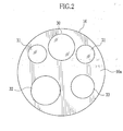
- the watering/airing nozzle 33 ejects water or air from a water reservoir or an air reservoir contained in the light source device 12 to the image capturing window 30 or a target body part in response to the operation of a watering/airing button 22 (refer to Fig. 1 ) on the operation section 14.
- the CPU 41 controls actuation of the electronic endoscope 10.
- the TG 43 generates drive pulses (vertical and horizontal scan pulses, a reset pulse, and the like) based on a reference clock signal from the reference clock oscillator 42, and drives the solid-state image sensor 40.
- the TG 43 also generates a synchronizing signal for the AFE 44 and inputs the synchronizing signal to the AFE 44.
- the solid-state image sensor 40 captures images inside the human body cavity in response to the drive pulses from the TG 43, and outputs an image signal.
- the number of pixels of the solid-state image sensor 40 varies from model to model of the electronic endoscope 10.
- the clock frequency of the reference clock oscillator 42 is determined in accordance with the number of pixels of the solid-state image sensor 40 so that the image signal of a constant number of frames (for example, 60 frames) is outputted per second even if the solid-state image sensor 40 has the different number of pixels.
- the AFE 44 is constituted of a correlated double sampling circuit (CDS) 47, an automatic gain controller (AGC) 48, and an analog-to-digital converter (A/D) 49.
- the CDS 47 applies correlated double sampling processing to the image signal outputted from the solid-state image sensor 40 in order to remove reset noise and amplifier noise.
- the AGC 48 amplifies the image signal without noise by designated gain.
- the A/D 49 converts the amplified image signal into a digital signal of a predetermined number of bits, and inputs the digital signal to the processor device 11 through the connector 19.
- the TG 43 generates a first horizontal synchronizing signal "HD1”, a first vertical synchronizing signal “VD1”, and a first clock signal “CLK1”, and inputs the signals “HD1", “VD1”, and "CLK1” to the processor device 11 through the connector 19.
- These signals "HD1", “VD1”, and “CLK1” synchronize with the image signal outputted from the AFE 44.
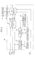
- the processor device 11 includes a CPU 50, isolation devices (IDs) 51 and 52, a digital signal processor (DSP) 53, a first synchronizing signal generator (first SSG) 54, a digital-to-analog converter (D/A) 55, a slot 57, and a connector 58.
- the CPU 50 controls individual circuits in the processor device 11 and the actuation of the light source device 12.
- the IDs 51 and 52 electrically separate the electronic endoscope 10 from the processor device 11.
- An option circuit board 56 is connected to the slot 57, and the TV monitor 20 is connected to the connector 58.
- the first horizontal synchronizing signal "HD1”, the first vertical synchronizing signal “VD1”, and the first clock signal “CLK1” are inputted through the ID 52.
- the first SSG 54 corrects deviation in phase among the first horizontal synchronizing signal “HD1”, the first vertical synchronizing signal “VD1”, and the first clock signal “CLK1”, and produces a second horizontal synchronizing signal "HD2", a second vertical synchronizing signal “VD2”, and a second clock signal "CLK2".
- the first SSG 54 inputs these signals “HD2", “VD2", and "CLK2" to the option circuit board 56 through the DSP 53 and the slot 57.
- the image signal outputted from the AFE 44 of the electronic endoscope 10 is inputted through the ID 51.
- the DSP 53 subjects the image signal to image processing such as color separation, color interpolation, gain correction, white balance correction, gamma correction, and image enhancement in order to generate a YC-format image data (video signal) "VS".
- the video signal "VS” consists of a luminance (Y) signal and a color difference (C) signal.
- the DSP 53 inputs the video signal "VS” to the D/A 55 and the option circuit board 56 through the slot 57.
- the D/A 55 converts the video signal "VS” into an NTSC-format analog video signal "NTSC”, and outputs the analog video signal "NTSC" to the TV monitor 20 connected to the connector 58.
- the light source device 12 is constituted of a light source 60 such as a xenon lamp and a halogen lamp, a light source driver 61 for driving the light source 60, an aperture stop mechanism 62 and a condenser lens 63 disposed between the light source 60 and the light guide 70, and a CPU 64 for controlling the light source driver 61 and the aperture stop mechanism 62 by communicating with the CPU 50 of the processor device 11.
- the aperture stop mechanism 62 increases or decreases the amount of light incident upon the light guide 70.
- the condense lens 63 condenses light, which has passed through the aperture stop mechanism 62, and leads the light into an entry of the light guide 70. The light further propagates through the light guide 70, and is applied to the target body part through the lighting windows 31 as described above.
- the measurement pulse generator 81 generates a measurement pulse signal that has higher frequency than the second clock signal "CLK2", and inputs the measurement pulse signal to the pulse counter 83.
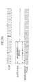
- the gate pulse generator 82 counts a predetermined number of rising edges of the second clock signal "CLK2" (for example, 10 pulses of the second clock signal "CLK2”) to generate a gate pulse signal.
- the gate pulse signal stays at a high level during a counted period and at a low level during a no-counted period.
- the generated gate pulse signal is inputted to the pulse counter 83.
- the microprocessor 84 judges the number of pixels (resolution) of the solid-state image sensor 40 based on the count value of the pulse counter 83.
- the memory 88 stores data that indicates the relation between the count values and the numbers of pixels.
- the microprocessor 84 retrieves the number of pixels corresponding to the inputted count value from the data stored in the memory 88. For example, when the count value is 24 to 26 pulses, the number of pixels of the solid-state image sensor 40 is judged to be "640 ⁇ 480". When the count value is 12 to 13 pulses, the number of pixels is judged to be "1280 ⁇ 960".
- the microprocessor 84 actuates the gate pulse generator 82 and the pulse counter 83 only during initialization just after turning the processor device 11 on, for the purpose of judging the number of pixels of the solid-state image sensor 40.
- the number of pixels judged is inputted to the DVI circuit 85.
- the DVI circuit 85 determines a display pixel number (display resolution) based on the number of pixels (resolution) of the solid-state image sensor 40 inputted from the microprocessor 84.
- the DVI circuit 85 also generates a digital video signal for a PC monitor 87 based on the video signal "VS" inputted from the processor device 11 and the third horizontal synchronizing signal "HD3" and the third vertical synchronizing signal "VD3" inputted from the second SSG 80.
- the DVI circuit 85 outputs the generated digital video signal to the PC monitor 87 that is connected to the option circuit board 56 via the connector 86 to display the endoscope images.
- the electronic endoscope 10 is first connected to the processor device 11 and the light source device 12 via the connector 19. Then, the endoscope system 2 is turned on, and the insert section 13 of the electronic endoscope 10 is introduced into the human body cavity.
- the solid-state image sensor 40 captures the images inside the human body cavity while the light from the light source device 12 illuminates there. The images are displayed on the NTSC-format TV monitor 20 connected to the processor device 11.
- the gate pulse generator 82 and the pulse counter 83 in the option circuit board 56 are actuated in response to turning the processor device 11 on.
- the gate pulse generator 82 counts a predetermined number of pulses of the inputted second clock signal "CLK2" to generate the gate pulse signal that sets the measurement period.
- the pulse counter 83 counts the number of measurement pulses generated from the measurement pulse generator 81 during the measurement period, and inputs the count value to the microprocessor 84.
- the microprocessor 84 judges the number of pixels (resolution) of the solid-state image sensor 40 based on the inputted count value, and inputs the judged number of pixels to the DVI circuit 85.
- the DVI circuit 85 determines the display resolution on the PC monitor 87 based on the inputted number of pixels.
- the DVI circuit 85 generates the digital video signal that corresponds to the display resolution.
- the DVI circuit 85 outputs the digital video signal to the PC monitor 87 through the connector 86, so that the images inside the human body cavity are displayed on the PC monitor 87 too.
- the option circuit board 56 since the option circuit board 56 judges the number of pixels based on the second clock signal "CLK2" inputted from the processor device 11 without communicating with the CPU 50 of the processor device 11, the option circuit board 56 quickly starts producing the digital video signal for the PC monitor 87. Thus, it is possible to reduce time from power-up till the PC monitor 87 starts displaying the images. Also, becomes unnecessary a communication line for communicating the number of pixels between the processor device 11 and the option circuit board 56.
- the video signal "VS" and the second clock signal “CLK2" are inputted to a fourth synchronizing signal generator (fourth SSG) 93.
- the fourth SSG 93 produces a synchronizing signal "SYNC” that synchronizes with the second clock signal "CLK2" from the video signal "VS” and the second clock signal "CLK2".
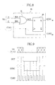
- the fourth SSG 93 is constituted of an OR circuit 94 and a D flip-flop 95.
- the video signal "VS" consists of an 8-bit luminance (Y) signal and an 8-bit color difference (C) signal. Eight bits of the Y signal are inputted to the OR circuit 94 in parallel, and eight bits of the C signal are inputted thereto in parallel.
- the OR circuit 94 outputs a low-level signal when all bits of the Y signal and the C signal are "0", and outputs a high-level signal when at least one bit thereof is "1" (refer to "OUT" of Fig. 9 ).
- An output signal "OUT" of the OR circuit 94 is inputted to a data input terminal "D" of the D flip-flop 95, and the second clock signal “CLK2" is inputted to a clock input terminal thereof.
- the D flip-flop 95 samples the output signal "OUT” at rising edges of the second clock signal “CLK2” and holds data. Accordingly, the synchronizing signal “SYNC” that synchronizes with the second clock signal “CLK2” is outputted from a data output terminal "Q" of the D flip-flop 95.
- the endoscope system 90 produces the synchronizing signal "SYNC" from the video signal "VS” and the second clock signal "CLK2", it is possible to further reduce the number of communication lines between the processor device 11 and the option circuit board 56.
- the present invention is applicable to an option circuit board that outputs another-format video signal such as a high vision video signal (HDTV signal).
- a high vision video signal HDTV signal
Landscapes
- Health & Medical Sciences (AREA)
- Life Sciences & Earth Sciences (AREA)
- Surgery (AREA)
- Biomedical Technology (AREA)
- Medical Informatics (AREA)
- Optics & Photonics (AREA)
- Pathology (AREA)
- Radiology & Medical Imaging (AREA)
- Biophysics (AREA)
- Engineering & Computer Science (AREA)
- Physics & Mathematics (AREA)
- Heart & Thoracic Surgery (AREA)
- Nuclear Medicine, Radiotherapy & Molecular Imaging (AREA)
- Molecular Biology (AREA)
- Animal Behavior & Ethology (AREA)
- General Health & Medical Sciences (AREA)
- Public Health (AREA)
- Veterinary Medicine (AREA)
- Endoscopes (AREA)
- Closed-Circuit Television Systems (AREA)
- Studio Devices (AREA)
- Instruments For Viewing The Inside Of Hollow Bodies (AREA)
Applications Claiming Priority (1)
| Application Number | Priority Date | Filing Date | Title |
|---|---|---|---|
| JP2008131927A JP5132419B2 (ja) | 2008-05-20 | 2008-05-20 | 内視鏡システム及びオプション基板 |
Publications (2)
| Publication Number | Publication Date |
|---|---|
| EP2123208A2 true EP2123208A2 (fr) | 2009-11-25 |
| EP2123208A3 EP2123208A3 (fr) | 2012-11-07 |
Family
ID=41056875
Family Applications (1)
| Application Number | Title | Priority Date | Filing Date |
|---|---|---|---|
| EP09006540A Withdrawn EP2123208A3 (fr) | 2008-05-20 | 2009-05-14 | Système d'endoscope avec carte de circuit d'option |
Country Status (3)
| Country | Link |
|---|---|
| US (1) | US20090290018A1 (fr) |
| EP (1) | EP2123208A3 (fr) |
| JP (1) | JP5132419B2 (fr) |
Families Citing this family (6)
| Publication number | Priority date | Publication date | Assignee | Title |
|---|---|---|---|---|
| JP2006115964A (ja) * | 2004-10-20 | 2006-05-11 | Fujinon Corp | 電子内視鏡装置 |
| JP2011250835A (ja) * | 2010-05-31 | 2011-12-15 | Olympus Corp | 内視鏡システム |
| CN103250406B (zh) * | 2010-12-14 | 2017-03-01 | 奥林巴斯株式会社 | 摄像装置 |
| US8854383B2 (en) * | 2011-04-13 | 2014-10-07 | Qualcomm Incorporated | Pixel value compaction for graphics processing |
| CN107529974B (zh) * | 2015-08-07 | 2020-03-13 | 奥林巴斯株式会社 | 摄像装置 |
| WO2020044637A1 (fr) * | 2018-08-28 | 2020-03-05 | オリンパス株式会社 | Endoscope, procédé d'entraînement, et programme |
Citations (2)
| Publication number | Priority date | Publication date | Assignee | Title |
|---|---|---|---|---|
| JP2003024272A (ja) | 2001-07-18 | 2003-01-28 | Olympus Optical Co Ltd | 信号処理装置 |
| JP2005296534A (ja) | 2004-04-16 | 2005-10-27 | Fujinon Corp | 電子内視鏡装置 |
Family Cites Families (9)
| Publication number | Priority date | Publication date | Assignee | Title |
|---|---|---|---|---|
| JP2547226B2 (ja) * | 1987-10-20 | 1996-10-23 | オリンパス光学工業株式会社 | 電子内視鏡装置 |
| JP2000201284A (ja) * | 1999-01-08 | 2000-07-18 | Fuji Photo Optical Co Ltd | Ntsc/pal判定装置及び電子内視鏡装置 |
| US6902527B1 (en) * | 1999-05-18 | 2005-06-07 | Olympus Corporation | Endoscope system with charge multiplying imaging device and automatic gain control |
| JP2001258836A (ja) * | 2000-03-16 | 2001-09-25 | Fuji Photo Optical Co Ltd | 電子内視鏡装置 |
| JP3487803B2 (ja) * | 2000-03-16 | 2004-01-19 | Nec液晶テクノロジー株式会社 | サンプリングクロックの調整方法及びディジタル表示装置用のインターフェイス回路 |
| US7050086B2 (en) * | 2001-06-26 | 2006-05-23 | Pentax Corporation | Electronic endoscope system with color-balance alteration process |
| JP2005118159A (ja) * | 2003-10-14 | 2005-05-12 | Fujinon Corp | 電子内視鏡装置 |
| JP4426854B2 (ja) * | 2004-01-27 | 2010-03-03 | 富士フイルム株式会社 | 電子内視鏡装置 |
| JP4926422B2 (ja) * | 2005-07-26 | 2012-05-09 | ローム株式会社 | 画像処理装置及びこれを用いた電子機器 |
-
2008
- 2008-05-20 JP JP2008131927A patent/JP5132419B2/ja not_active Expired - Fee Related
-
2009
- 2009-05-14 EP EP09006540A patent/EP2123208A3/fr not_active Withdrawn
- 2009-05-19 US US12/453,687 patent/US20090290018A1/en not_active Abandoned
Patent Citations (3)
| Publication number | Priority date | Publication date | Assignee | Title |
|---|---|---|---|---|
| JP2003024272A (ja) | 2001-07-18 | 2003-01-28 | Olympus Optical Co Ltd | 信号処理装置 |
| US7429242B2 (en) | 2001-07-18 | 2008-09-30 | Olympus Corporation | Electronic endoscope apparatus and signal processing apparatus having detachable option substrate |
| JP2005296534A (ja) | 2004-04-16 | 2005-10-27 | Fujinon Corp | 電子内視鏡装置 |
Also Published As
| Publication number | Publication date |
|---|---|
| US20090290018A1 (en) | 2009-11-26 |
| JP2009279061A (ja) | 2009-12-03 |
| JP5132419B2 (ja) | 2013-01-30 |
| EP2123208A3 (fr) | 2012-11-07 |
Similar Documents
| Publication | Publication Date | Title |
|---|---|---|
| US8403835B2 (en) | Endoscope system and drive control method thereof | |
| EP2094002A2 (fr) | Système de communication d'endoscope et système d'endoscope | |
| EP2123208A2 (fr) | Système d'endoscope avec carte de circuit d'option | |
| EP2096865A2 (fr) | Système de capture d'images et système d'endoscope | |
| US8749625B2 (en) | Method for resetting CMOS imaging element in endoscope apparatus | |
| CN102753083B (zh) | 电子内窥镜系统 | |
| JP2011206333A (ja) | 内視鏡装置におけるcmos撮像素子の電源装置 | |
| EP2135544A1 (fr) | Dispositif de processeur et procédé d'affichage d'image | |
| EP2674100A1 (fr) | Système endoscopique | |
| JP2010088656A (ja) | 内視鏡用プロセッサ装置、内視鏡用プロセッサ装置の電源電圧供給方法、並びに内視鏡システム | |
| US10188266B2 (en) | Endoscopic imaging device for reducing data amount of image signal | |
| EP2328340A2 (fr) | Système endoscope électronique, appareil de traitement pour l'endoscope électronique et procédé de séparation de signaux | |
| US11160443B2 (en) | Electronic endoscope device for changing observation image brightness | |
| JP5336410B2 (ja) | 内視鏡システム及びその作動方法 | |
| JP2005305124A (ja) | 電子内視鏡装置 | |
| JP4426909B2 (ja) | 内視鏡用カメラヘッド、内視鏡用カメラシステム、及び内視鏡システム | |
| JP4315538B2 (ja) | 内視鏡システム | |
| JP2014033788A (ja) | 撮像装置および撮像システム | |
| US20090225219A1 (en) | Image pickup system | |
| WO2021171427A1 (fr) | Dispositif de commande, endoscope et procédé de commande | |
| JP2001145099A (ja) | 内視鏡装置及び内視鏡システム | |
| JP2008253587A (ja) | 内視鏡システム | |
| JP5570273B2 (ja) | 内視鏡システム | |
| JP2010004980A (ja) | 電子内視鏡用プロセッサ装置 | |
| JP4398106B2 (ja) | 撮像素子駆動ユニットとこれを用いる撮像装置 |
Legal Events
| Date | Code | Title | Description |
|---|---|---|---|
| PUAI | Public reference made under article 153(3) epc to a published international application that has entered the european phase |
Free format text: ORIGINAL CODE: 0009012 |
|
| AK | Designated contracting states |
Kind code of ref document: A2 Designated state(s): AT BE BG CH CY CZ DE DK EE ES FI FR GB GR HR HU IE IS IT LI LT LU LV MC MK MT NL NO PL PT RO SE SI SK TR |
|
| PUAL | Search report despatched |
Free format text: ORIGINAL CODE: 0009013 |
|
| AK | Designated contracting states |
Kind code of ref document: A3 Designated state(s): AT BE BG CH CY CZ DE DK EE ES FI FR GB GR HR HU IE IS IT LI LT LU LV MC MK MT NL NO PL PT RO SE SI SK TR |
|
| AX | Request for extension of the european patent |
Extension state: AL BA RS |
|
| RIC1 | Information provided on ipc code assigned before grant |
Ipc: A61B 1/045 20060101ALI20120928BHEP Ipc: A61B 1/00 20060101AFI20120928BHEP |
|
| STAA | Information on the status of an ep patent application or granted ep patent |
Free format text: STATUS: THE APPLICATION HAS BEEN WITHDRAWN |
|
| 17P | Request for examination filed |
Effective date: 20130211 |
|
| 18W | Application withdrawn |
Effective date: 20130312 |