EP2123245B1 - Fauteuil roulant, en particulier fauteuil roulant actif, doté d'un adaptateur de liaison - Google Patents
Fauteuil roulant, en particulier fauteuil roulant actif, doté d'un adaptateur de liaison Download PDFInfo
- Publication number
- EP2123245B1 EP2123245B1 EP08009192A EP08009192A EP2123245B1 EP 2123245 B1 EP2123245 B1 EP 2123245B1 EP 08009192 A EP08009192 A EP 08009192A EP 08009192 A EP08009192 A EP 08009192A EP 2123245 B1 EP2123245 B1 EP 2123245B1
- Authority
- EP
- European Patent Office
- Prior art keywords
- seat
- wheelchair
- wheelchair according
- connection adapter
- arc
- Prior art date
- Legal status (The legal status is an assumption and is not a legal conclusion. Google has not performed a legal analysis and makes no representation as to the accuracy of the status listed.)
- Active
Links
Images





Classifications
-
- A—HUMAN NECESSITIES
- A61—MEDICAL OR VETERINARY SCIENCE; HYGIENE
- A61G—TRANSPORT, PERSONAL CONVEYANCES, OR ACCOMMODATION SPECIALLY ADAPTED FOR PATIENTS OR DISABLED PERSONS; OPERATING TABLES OR CHAIRS; CHAIRS FOR DENTISTRY; FUNERAL DEVICES
- A61G5/00—Chairs or personal conveyances specially adapted for patients or disabled persons, e.g. wheelchairs
- A61G5/10—Parts, details or accessories
-
- A—HUMAN NECESSITIES
- A61—MEDICAL OR VETERINARY SCIENCE; HYGIENE
- A61G—TRANSPORT, PERSONAL CONVEYANCES, OR ACCOMMODATION SPECIALLY ADAPTED FOR PATIENTS OR DISABLED PERSONS; OPERATING TABLES OR CHAIRS; CHAIRS FOR DENTISTRY; FUNERAL DEVICES
- A61G5/00—Chairs or personal conveyances specially adapted for patients or disabled persons, e.g. wheelchairs
- A61G5/10—Parts, details or accessories
- A61G5/1056—Arrangements for adjusting the seat
- A61G5/1059—Arrangements for adjusting the seat adjusting the height of the seat
-
- A—HUMAN NECESSITIES
- A61—MEDICAL OR VETERINARY SCIENCE; HYGIENE
- A61G—TRANSPORT, PERSONAL CONVEYANCES, OR ACCOMMODATION SPECIALLY ADAPTED FOR PATIENTS OR DISABLED PERSONS; OPERATING TABLES OR CHAIRS; CHAIRS FOR DENTISTRY; FUNERAL DEVICES
- A61G5/00—Chairs or personal conveyances specially adapted for patients or disabled persons, e.g. wheelchairs
- A61G5/10—Parts, details or accessories
- A61G5/1056—Arrangements for adjusting the seat
- A61G5/107—Arrangements for adjusting the seat positioning the whole seat forward or rearward
-
- A—HUMAN NECESSITIES
- A61—MEDICAL OR VETERINARY SCIENCE; HYGIENE
- A61G—TRANSPORT, PERSONAL CONVEYANCES, OR ACCOMMODATION SPECIALLY ADAPTED FOR PATIENTS OR DISABLED PERSONS; OPERATING TABLES OR CHAIRS; CHAIRS FOR DENTISTRY; FUNERAL DEVICES
- A61G5/00—Chairs or personal conveyances specially adapted for patients or disabled persons, e.g. wheelchairs
- A61G5/10—Parts, details or accessories
- A61G5/1081—Parts, details or accessories with shock absorbers or other suspension arrangements between frame and seat
Definitions
- the invention relates to a rigid frame wheelchair, in particular an active wheelchair.
- Active wheelchairs which are in particular so-called rigid frame wheelchairs, in contrast to folding wheelchairs, are intended for users who operate the wheelchair predominantly themselves, thus actively.
- To this Wheelchairs are subject to high demands regarding the adaptability to the patient, in particular with respect to his position to the rear axle.
- the shoulder should be positionable over the axis of the drive wheels. This requires that the rear axle and seat, thus horizontal seat cushion and backrest, must be horizontally adjustable against each other. But it also plays the seat angle relative to the horizontal for the active position a major role and must be individually adjustable. As a rule, the rear seat edge is lower than the seat leading edge.
- connection adapter for frame tubes, seat support, which are also usually also pipes, and rear axle are known. See for example also WO 2006/017843 .
- the active wheelchair "Blizzard" by the company Otto Bock (www.ottobock.de of May 15, 2008) clearly shows a milled part, which establishes the connection from the seat tube to the rear axle.
- the seat tube is at the same time frame tube on which z. B. the steerable front wheels are mounted.
- the milled part is moved on the seat tube / frame tube and clamped thereon.
- the wheelbase and seat angle are changing.
- the seat angle to the horizontal is set by offsetting the rear axle on the milled part. This simultaneously changes the angle of the frame tube on which the front wheels are mounted so that they would have to be readjusted for vertical alignment of the steering fork axis.
- a corresponding device in this case for clamping the round axle bearing in the steering fork mount, is always present in such wheelchairs.
- These adjustments and adjustments are complex and often the steering forks are not set correctly.
- a folding wheelchair wherein the folding of the wheelchair is accomplished by means of a scissor link arrangement.
- Two scissor-link elements of the scissor link arrangement which are pivotable about a common axis arranged in the longitudinal direction of the wheelchair have tubular seat support elements extending in the longitudinal direction of the wheelchair in the region of their upper ends Rest on recordings.
- the respective connection adapter is connected to side struts of a chassis of the wheelchair and a rear axle.
- the invention proposes a rigid frame wheelchair, in particular active wheelchair ago, according to claim 1, with horrendern, with side struts of a chassis a rear axle and seat mounts are connected for a seat of the wheelchair, wherein the respective connection adapter for adjusting the seat angle has a circular arc-shaped contour for receiving a seat receiver with a corresponding circular arc-shaped contour.
- the rigid frame wheelchair is referred to simply as "wheelchair" for the sake of simplicity.
- the respective connection adapter is provided in its upper region with a recess which has the circular-arc-shaped contour and it is the seat receiving in its lower region provided with the circular arc-shaped contour. Weight forces of the person sitting on the wheelchair are thus introduced directly via the respective seat receptacle in the associated connection adapter.
- connection adapters for adjusting a wheelbase on the side struts are displaced.
- connection adapter is mounted in a height-adjustable manner in the rear axle.
- respective seat mount should be height-adjustable be mounted in the connection adapter or the seat to be height-adjustable stored in the seat mounts. It is also advantageous if the seat is mounted horizontally adjustable in the seat mounts. Through these measures, the wheelchair can be optimally adapted to the ergonomic conditions of the wheelchair users.
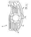
- the respective seat receptacle is expediently substantially plate-shaped. It is formed by at least one plate, in particular by the plate and a mounted in this bracket for supporting the seat.
- the seat receptacle can be produced particularly easily and it may have additional functions by special design, in particular by providing the plate with slots and holes, apart from the actual function of recording the seat.
- the bracket is mounted in at least one slot or in slots.
- the plate has at least two parallel slots. In the longitudinal direction of the slot or in the longitudinal direction of the slots is thus a substantially horizontal Relatiwer ein of bracket and plate, therefore a Relatiwerwolf of seat and seat mounts possible. It is also conceivable to make the plate so that it has at least two parallel slots. This makes it possible to position the retaining plate at different height level.
- connection adapter consists of two halves separated perpendicular to the rear axle. This design of the connection adapter makes it possible to arrange functional parts between the two halves, to position them differently there and to connect or latch them.
- connection adapter for fixing the seat receiving at least one opening for receiving a clamping element or a locking unit.
- clamping element makes it possible to fix the seat receptacle with respect to the connection adapter in any position of the seat receptacle while the locking unit permits the seat receptacle to be fixed in one of various defined positions.
- the seat receptacle in particular in the lower region, at least one extending over a circular arc slot for seat angle adjustment, wherein the slot coincides with at least one screw hole and at least one opening for a clamping unit.
- the seat receptacle in particular in the lower region, arranged over a circular arc, having a plurality of holes for latching with an adapter-side locking.
- connection adapter in particular a half of the adapter, has a recess for receiving a circular arc-shaped guide rail.
- This guide rail is ideally suited to absorb the relatively high forces that are introduced via the person sitting on the wheelchair in the seat.
- the guide rail is preferably metal.
- the connection adapter consists in particular of plastic. This design of the bearing rail mounted in the recess of the connection adapter makes it possible to accommodate and guide the seat mounts particularly easily.
- the guide rail passes through an arcuate groove of the seat receptacles.
- This groove of the seat receptacle is significantly longer than the guide rail, so that the guide rail between the two ends of the slot of the seat receptacle can be moved and thereby represent different angles of inclination of the seat. It is particularly contemplated that the seat receptacle with respect to the connection adapter by an angle of up to 50 °, in particular by an angle to the horizontal of -5 ° to + 15 ° or -5 ° to + 45 ° is pivotable. In the former case with the pivoting about the relatively small angle, the use of the wheelchair as an active wheelchair is preferred. If it is not an active wheelchair is preferably the larger Winkelverstell Sector provided.
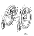
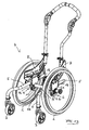
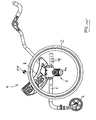
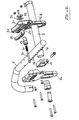
- connection adapter 6 preferably consist of two adapter halves, the outer adapter half 6a and the inner adapter half 6b.
- the separation plane is perpendicular to the rear axle 9 and preferably through the center line of the side struts 5.
- the adapter halves 6a and 6b each have a diameter of the side struts 5 corresponding recess 10.
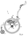
- the rear axle 9 is received in the connection adapters 6 by means of position adapters 11 below the side struts 5. Row of holes 12 in the adapter halves 6a and 6b allow the height adjustment of the rear axle.
- the seat mounts 7 and 8 are received above the side struts 5 in the kausadaptern 6 and are rotatably mounted therein.
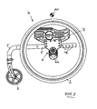
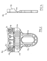
- the adapter halves 6a and 6b have in their upper region of the plate thickness corresponding and circular arc-shaped recesses 13.
- the seat mounts 7 and 8 likewise have an arcuate contour 14 in their lower region.
- the pivot point MP corresponds to the center of the circle. This center MP should come as close as possible to the center of gravity of the patient-seat system.
- an adapted seat 17 can be adjusted horizontally with respect to the rear axle 9 in order to be able to set an optimum position, in particular for active driving, without changing the geometry of the chassis.
- two sets of slots 15 are mounted one above the other.
- connection adapter 6 can be moved to the side struts 5 corresponding to the holes 18. It would also be conceivable a purely non-positive clamping on the side struts. In this case, both the seat angle and the horizontal distance from the rear axle 9 to the back surface of the seat 17 are maintained.
- the seat mounts 7 are for in the FIGS. 1 to 11 illustrated active wheelchair 1, in which the seat unit is to be set only in a certain, relatively small angle (about -5 ° to + 15 °) relative to the horizontal.
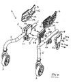
- the seat mounts 7 have in their lower region near and parallel to the arcuate contour 14 two (possibly more, but at least one) through a thin web for the purpose of stabilizing separate radial slots 19, with screw holes 20 in the outer adapter halves 6 a and 21 breakthroughs in the inner adapter halves 6b lie in cover.
- In the openings 21 each have a clamping element 22 against rotation, but slidably mounted in the longitudinal direction of the openings 21.
- Screws 23 in the screw holes 20 penetrate the radial oblong holes 19 (secure the seat mounts 7) and are screwed into the clamping elements 22, causing them to pull against the seat mounts 7 and clamp against the outer adapter halves 6 a. By loosening the screws 23, the seat mounts 7 are released and can slide in the recesses 13 rotating.
- the radius of the recesses 13 and the contour 14 is selected so that the center MP or the pivot point as close to the center of gravity of the system patient-seat - ie above the seat and before Backrest - to lie down. An exact determination is dispensed with in favor of a simple construction and adjustment.
- the seat mounts 8 are in a wheelchair according to the embodiment of the FIGS. 12 to 19 , thus a sliding wheelchair used when the seat unit is tilted adjustable over a larger angular range (about -5 ° to + 45 °).
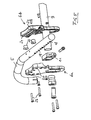
- the seat mounts 8 have in their lower area close and parallel to the circular contour 14 a series of radially arranged holes 24 and on one side a radial, about the area of the holes 24 and to the front beyond extending approximately 4 mm deep groove 25.
- a guide rail 26 is mounted with one half in a recess 27 of the inner adapter half 6b and with the other half in the groove 25 of the seat receptacle 8 and prevents jumping out of the seat receptacles 8 from the kausadaptern 6.
- the seat mounts 8 are locked in one of the holes 24 according to the desired adjustment angle of the seat.
- the latches 28 are each preferably screwed into the rear openings 21 of the inner adapter halves 6. The associated release mechanism is not shown for the sake of clarity.
- a seat angle adjustment is made possible without having to change or change the geometry of the chassis or the position of the center of gravity of the user relative to the rear axle.
- connection adapter 6 need not necessarily be designed in the illustrated form, in which the rear axle 9 is arranged below the side struts 5. Also conceivable is an arrangement above the side struts 5. This would position the seat closer to the rear axle and the user deeper between the drive wheels. Also, the rear axle 9 does not necessarily have to be designed continuously. Drive wheels could also be attached directly to the position adapter 11 detachable or fixed.
Landscapes
- Health & Medical Sciences (AREA)
- Life Sciences & Earth Sciences (AREA)
- Animal Behavior & Ethology (AREA)
- General Health & Medical Sciences (AREA)
- Public Health (AREA)
- Veterinary Medicine (AREA)
- Handcart (AREA)
- Seats For Vehicles (AREA)
- Carriages For Children, Sleds, And Other Hand-Operated Vehicles (AREA)
Claims (15)
- Fauteuil roulant à cadre rigide, en particulier fauteuil roulant actif, comprenant des adaptateurs de liaison (6, 6) qui sont reliés à des montants latéraux (5, 5) d'un châssis (4), un essieu arrière (9) et des logements de siège (7, 7 respectivement 8, 8) pour un siège (17) du fauteuil roulant (1), l'adaptateur de liaison (6) présentant, pour le réglage angulaire du siège, un contour (13) en forme d'arc de cercle pour recevoir un logement de siège (7 respectivement 8) avec un contour (14) de forme correspondante en arc de cercle.
- Fauteuil roulant selon la revendication 1, dans lequel l'adaptateur de liaison (6) présente, dans sa région supérieure, un évidement ayant le contour (13) en forme d'arc de cercle, et le logement de siège (7 respectivement 8) est pourvu, dans sa région inférieure, du contour (14) en forme d'arc de cercle.
- Fauteuil roulant selon la revendication 1 ou 2, dans lequel l'adaptateur de liaison (6) est monté de manière réglable en hauteur dans l'essieu arrière (9).
- Fauteuil roulant selon l'une quelconque des revendications 1 à 3, dans lequel le logement de siège (7 respectivement 8) est monté de manière réglable en hauteur dans l'adaptateur de liaison (6) ou le siège (17) est monté de manière réglable en hauteur dans les logements de siège (7, 7 respectivement 8, 8).
- Fauteuil roulant selon l'une quelconque des revendications 1 à 4, dans lequel le siège (17) est monté de manière réglable horizontalement dans les logements de siège (7, 7 respectivement 8, 8).
- Fauteuil roulant selon l'une quelconque des revendications 1 à 5, dans lequel le logement de siège (7 respectivement 8) est formé par au moins une plaque, en particulier par la plaque et un coude de retenue (16) monté dans celle-ci pour supporter le siège (17).
- Fauteuil roulant selon la revendication 6, dans lequel le coude de retenue (16) est déplaçable dans au moins un trou oblong (15) de la plaque ou est monté dans des trous, et des moyens de fixation sont prévus pour la fixation du coude de retenue (16) à la plaque.
- Fauteuil roulant selon la revendication 6 ou 7, dans lequel la plaque présente au moins deux trous oblongs (15) disposés parallèlement et/ou l'un derrière l'autre.
- Fauteuil roulant selon l'une quelconque des revendications 1 à 8, dans lequel l'adaptateur de liaison (6) se compose de deux moitiés (6a, 6b) séparées perpendiculairement à l'essieu arrière (9).
- Fauteuil roulant selon l'une quelconque des revendications 1 à 9, dans lequel l'adaptateur de liaison (6) présente, pour fixer le logement de siège (7 respectivement 8), au moins un orifice (21) pour recevoir un élément de serrage (22) ou une unité de verrouillage (28).
- Fauteuil roulant selon l'une quelconque des revendications 1 à 10, dans lequel le logement de siège (7), en particulier dans la région inférieure, présente au moins un trou oblong (19) s'étendant sur un arc de cercle en vue du réglage de l'angle du siège, le trou oblong (19) s'alignant avec au moins un trou de vissage (20) et au moins un orifice (21) pour un élément de serrage (22) ou le logement de siège (8), en particulier dans la région inférieure, présente plusieurs trous (24) disposés sur un arc de cercle, en vue de l'encliquetage avec un verrouillage (28) du côté de l'adaptateur.
- Fauteuil roulant selon l'une quelconque des revendications 1 à 11, dans lequel l'adaptateur de liaison (6), en particulier une moitié (6b) de l'adaptateur (6), présente un évidement (27) pour recevoir un rail de guidage (26) en forme d'arc de cercle.
- Fauteuil roulant selon la revendication 12, dans lequel le rail de guidage (26) vient en prise dans une rainure (25) en forme d'arc de cercle du logement de siège (8).
- Fauteuil roulant selon l'une quelconque des revendications 1 à 13, dans lequel le logement de siège (7 respectivement 8), peut pivoter par rapport à l'adaptateur de liaison (6) d'un angle allant jusqu'à 50°, en particulier d'un angle par rapport à l'horizontale de -5° à +15°, ou de -5° à +45°.
- Fauteuil roulant selon l'une quelconque des revendications 1 à 14, dans lequel les adaptateurs de liaison (6, 6) peuvent être réglés pour l'ajustement d'un écartement des roues au niveau des montants latéraux (5, 5).
Priority Applications (3)
| Application Number | Priority Date | Filing Date | Title |
|---|---|---|---|
| EP08009192A EP2123245B1 (fr) | 2008-05-19 | 2008-05-19 | Fauteuil roulant, en particulier fauteuil roulant actif, doté d'un adaptateur de liaison |
| AT08009192T ATE517597T1 (de) | 2008-05-19 | 2008-05-19 | Rollstuhl, insbesondere aktivrollstuhl, mit verbindungsadapter |
| US12/387,522 US20090283983A1 (en) | 2008-05-19 | 2009-05-04 | Wheelchair construction |
Applications Claiming Priority (1)
| Application Number | Priority Date | Filing Date | Title |
|---|---|---|---|
| EP08009192A EP2123245B1 (fr) | 2008-05-19 | 2008-05-19 | Fauteuil roulant, en particulier fauteuil roulant actif, doté d'un adaptateur de liaison |
Publications (2)
| Publication Number | Publication Date |
|---|---|
| EP2123245A1 EP2123245A1 (fr) | 2009-11-25 |
| EP2123245B1 true EP2123245B1 (fr) | 2011-07-27 |
Family
ID=39832568
Family Applications (1)
| Application Number | Title | Priority Date | Filing Date |
|---|---|---|---|
| EP08009192A Active EP2123245B1 (fr) | 2008-05-19 | 2008-05-19 | Fauteuil roulant, en particulier fauteuil roulant actif, doté d'un adaptateur de liaison |
Country Status (3)
| Country | Link |
|---|---|
| US (1) | US20090283983A1 (fr) |
| EP (1) | EP2123245B1 (fr) |
| AT (1) | ATE517597T1 (fr) |
Families Citing this family (8)
| Publication number | Priority date | Publication date | Assignee | Title |
|---|---|---|---|---|
| US8944454B2 (en) * | 2007-10-01 | 2015-02-03 | Pride Mobility Products Corporation | Dual-track tilt mechanism |
| EP2213269B1 (fr) * | 2009-01-30 | 2013-03-13 | Sunrise Medical GmbH & Co. KG | Transport de personnes, par exemple un fauteuil roulant et ensemble de cadre correspondant |
| ITMI20112309A1 (it) * | 2011-12-19 | 2013-06-20 | Gm Italia S R L | Carrozzella motorizzata |
| CA2872080C (fr) | 2012-05-07 | 2020-02-25 | Motion Composites Inc. | Ensemble support de roue arriere de fauteuil roulant et accoudoir detachable |
| WO2014138128A1 (fr) | 2013-03-04 | 2014-09-12 | Ki Mobility | Fauteuil roulant basculant dans l'espace utilisant plusieurs chemins de commande |
| DE202014102184U1 (de) * | 2014-05-09 | 2014-05-23 | Orth Gmbh | Sitzschalenadapter |
| JP6482134B2 (ja) * | 2016-09-26 | 2019-03-13 | 株式会社フォーカルワークス | 固定機構 |
| US10500112B1 (en) * | 2017-06-09 | 2019-12-10 | Wayne Harvey Hanson | Dynamic support system for a chair to provide a user multiple supported positions |
Family Cites Families (5)
| Publication number | Priority date | Publication date | Assignee | Title |
|---|---|---|---|---|
| DE20221601U1 (de) * | 1977-12-10 | 2006-07-27 | Sunrise Medical Ltd., Wollaston | Rollstuhl und Radanbringungsanordnung für diesen |
| US4639012A (en) * | 1986-04-14 | 1987-01-27 | The Boeing Company | Airborne folding wheelchair |
| CA2311934C (fr) * | 2000-06-19 | 2012-08-21 | Phil Mundy | Fauteuil roulant avec siege inclinable |
| US8474848B2 (en) * | 2003-03-31 | 2013-07-02 | Sunrise Medical (Us) Llc | Personal mobility vehicle with tiltable seat |
| DE202006010451U1 (de) * | 2006-07-04 | 2006-08-24 | Molab Gmbh | Rollstuhl mit Verbindungselement |
-
2008
- 2008-05-19 EP EP08009192A patent/EP2123245B1/fr active Active
- 2008-05-19 AT AT08009192T patent/ATE517597T1/de active
-
2009
- 2009-05-04 US US12/387,522 patent/US20090283983A1/en not_active Abandoned
Also Published As
| Publication number | Publication date |
|---|---|
| EP2123245A1 (fr) | 2009-11-25 |
| ATE517597T1 (de) | 2011-08-15 |
| US20090283983A1 (en) | 2009-11-19 |
Similar Documents
| Publication | Publication Date | Title |
|---|---|---|
| EP2123245A1 (fr) | Fauteuil roulant, en particulier fauteuil roulant actif, doté d'un adaptateur de liaison | |
| DE102011117671B4 (de) | Rollstuhl mit in der Höhe und Neigung verstellbarem Sitz | |
| DE20015115U1 (de) | Verstellvorrichtung für einen Fahrzeugsitz | |
| DE102014209462A1 (de) | Sitz für einen Fahrzeugführer einer Baumaschine, sowie Baumaschine | |
| DE2736550C2 (fr) | ||
| EP1134114A2 (fr) | Appui-tête pour sièges de véhicules | |
| EP1608530B1 (fr) | Appui-tete, utilise en particulier pour un siege de vehicule | |
| EP3556336A1 (fr) | Fauteuil roulant à cadre rigide | |
| DE19602909A1 (de) | Kopfstütze für Fahrzeugsitze | |
| EP0538610B1 (fr) | Chaise roulante | |
| WO2002065970A1 (fr) | Coque d'assise reglable | |
| DE102012219206B4 (de) | Dorsokinetische Rückenlehne eines Sitzmöbels, Sitzmöbel | |
| DE102005024541B3 (de) | Rückbank für ein Kraftfahrzeug | |
| DE202011101394U1 (de) | Lehnenanordnung für Rollstuhlfahrer zum Einbau in Kraftfahrzeugen | |
| DE29704034U1 (de) | Rollstuhl | |
| AT507037B1 (de) | Stuhl mit horizontal verstellbarem armlehnenteil | |
| DE10013564C1 (de) | Rollstuhl | |
| DE202008009608U1 (de) | Faltrollstuhl mit variabler Sitzbreite | |
| WO2007121606A1 (fr) | Fauteuil roulant | |
| EP3245997B1 (fr) | Chaise de traitement médical | |
| DE102013015529B4 (de) | Kraftfahrzeugsitz mit einer Rückenlehne und einem daran angeordneten, neigungsverstellbaren Lehnenkopfteil | |
| AT525218B1 (de) | Stuhl | |
| DE9107375U1 (de) | Tisch | |
| DE102013009090B4 (de) | Mechanisches Befestigungssystem | |
| DE202009015647U1 (de) | Sitz zum Befestigen an einer Tischplatte |
Legal Events
| Date | Code | Title | Description |
|---|---|---|---|
| PUAI | Public reference made under article 153(3) epc to a published international application that has entered the european phase |
Free format text: ORIGINAL CODE: 0009012 |
|
| AK | Designated contracting states |
Kind code of ref document: A1 Designated state(s): AT BE BG CH CY CZ DE DK EE ES FI FR GB GR HR HU IE IS IT LI LT LU LV MC MT NL NO PL PT RO SE SI SK TR |
|
| AX | Request for extension of the european patent |
Extension state: AL BA MK RS |
|
| 17P | Request for examination filed |
Effective date: 20100324 |
|
| AKX | Designation fees paid |
Designated state(s): AT BE BG CH CY CZ DE DK EE ES FI FR GB GR HR HU IE IS IT LI LT LU LV MC MT NL NO PL PT RO SE SI SK TR |
|
| GRAP | Despatch of communication of intention to grant a patent |
Free format text: ORIGINAL CODE: EPIDOSNIGR1 |
|
| GRAS | Grant fee paid |
Free format text: ORIGINAL CODE: EPIDOSNIGR3 |
|
| GRAA | (expected) grant |
Free format text: ORIGINAL CODE: 0009210 |
|
| AK | Designated contracting states |
Kind code of ref document: B1 Designated state(s): AT BE BG CH CY CZ DE DK EE ES FI FR GB GR HR HU IE IS IT LI LT LU LV MC MT NL NO PL PT RO SE SI SK TR |
|
| REG | Reference to a national code |
Ref country code: GB Ref legal event code: FG4D Free format text: NOT ENGLISH |
|
| REG | Reference to a national code |
Ref country code: CH Ref legal event code: EP |
|
| REG | Reference to a national code |
Ref country code: DE Ref legal event code: R096 Ref document number: 502008004310 Country of ref document: DE Effective date: 20110915 |
|
| REG | Reference to a national code |
Ref country code: CH Ref legal event code: NV Representative=s name: ISLER & PEDRAZZINI AG |
|
| REG | Reference to a national code |
Ref country code: NL Ref legal event code: VDEP Effective date: 20110727 |
|
| PG25 | Lapsed in a contracting state [announced via postgrant information from national office to epo] |
Ref country code: NO Free format text: LAPSE BECAUSE OF FAILURE TO SUBMIT A TRANSLATION OF THE DESCRIPTION OR TO PAY THE FEE WITHIN THE PRESCRIBED TIME-LIMIT Effective date: 20111027 Ref country code: NL Free format text: LAPSE BECAUSE OF FAILURE TO SUBMIT A TRANSLATION OF THE DESCRIPTION OR TO PAY THE FEE WITHIN THE PRESCRIBED TIME-LIMIT Effective date: 20110727 Ref country code: LT Free format text: LAPSE BECAUSE OF FAILURE TO SUBMIT A TRANSLATION OF THE DESCRIPTION OR TO PAY THE FEE WITHIN THE PRESCRIBED TIME-LIMIT Effective date: 20110727 Ref country code: HR Free format text: LAPSE BECAUSE OF FAILURE TO SUBMIT A TRANSLATION OF THE DESCRIPTION OR TO PAY THE FEE WITHIN THE PRESCRIBED TIME-LIMIT Effective date: 20110727 Ref country code: FI Free format text: LAPSE BECAUSE OF FAILURE TO SUBMIT A TRANSLATION OF THE DESCRIPTION OR TO PAY THE FEE WITHIN THE PRESCRIBED TIME-LIMIT Effective date: 20110727 Ref country code: IS Free format text: LAPSE BECAUSE OF FAILURE TO SUBMIT A TRANSLATION OF THE DESCRIPTION OR TO PAY THE FEE WITHIN THE PRESCRIBED TIME-LIMIT Effective date: 20111127 Ref country code: SE Free format text: LAPSE BECAUSE OF FAILURE TO SUBMIT A TRANSLATION OF THE DESCRIPTION OR TO PAY THE FEE WITHIN THE PRESCRIBED TIME-LIMIT Effective date: 20110727 Ref country code: PT Free format text: LAPSE BECAUSE OF FAILURE TO SUBMIT A TRANSLATION OF THE DESCRIPTION OR TO PAY THE FEE WITHIN THE PRESCRIBED TIME-LIMIT Effective date: 20111128 |
|
| PG25 | Lapsed in a contracting state [announced via postgrant information from national office to epo] |
Ref country code: GR Free format text: LAPSE BECAUSE OF FAILURE TO SUBMIT A TRANSLATION OF THE DESCRIPTION OR TO PAY THE FEE WITHIN THE PRESCRIBED TIME-LIMIT Effective date: 20111028 Ref country code: SI Free format text: LAPSE BECAUSE OF FAILURE TO SUBMIT A TRANSLATION OF THE DESCRIPTION OR TO PAY THE FEE WITHIN THE PRESCRIBED TIME-LIMIT Effective date: 20110727 Ref country code: LV Free format text: LAPSE BECAUSE OF FAILURE TO SUBMIT A TRANSLATION OF THE DESCRIPTION OR TO PAY THE FEE WITHIN THE PRESCRIBED TIME-LIMIT Effective date: 20110727 Ref country code: CY Free format text: LAPSE BECAUSE OF FAILURE TO SUBMIT A TRANSLATION OF THE DESCRIPTION OR TO PAY THE FEE WITHIN THE PRESCRIBED TIME-LIMIT Effective date: 20110727 Ref country code: PL Free format text: LAPSE BECAUSE OF FAILURE TO SUBMIT A TRANSLATION OF THE DESCRIPTION OR TO PAY THE FEE WITHIN THE PRESCRIBED TIME-LIMIT Effective date: 20110727 |
|
| REG | Reference to a national code |
Ref country code: IE Ref legal event code: FD4D |
|
| PG25 | Lapsed in a contracting state [announced via postgrant information from national office to epo] |
Ref country code: SK Free format text: LAPSE BECAUSE OF FAILURE TO SUBMIT A TRANSLATION OF THE DESCRIPTION OR TO PAY THE FEE WITHIN THE PRESCRIBED TIME-LIMIT Effective date: 20110727 Ref country code: CZ Free format text: LAPSE BECAUSE OF FAILURE TO SUBMIT A TRANSLATION OF THE DESCRIPTION OR TO PAY THE FEE WITHIN THE PRESCRIBED TIME-LIMIT Effective date: 20110727 Ref country code: IE Free format text: LAPSE BECAUSE OF FAILURE TO SUBMIT A TRANSLATION OF THE DESCRIPTION OR TO PAY THE FEE WITHIN THE PRESCRIBED TIME-LIMIT Effective date: 20110727 |
|
| PG25 | Lapsed in a contracting state [announced via postgrant information from national office to epo] |
Ref country code: RO Free format text: LAPSE BECAUSE OF FAILURE TO SUBMIT A TRANSLATION OF THE DESCRIPTION OR TO PAY THE FEE WITHIN THE PRESCRIBED TIME-LIMIT Effective date: 20110727 Ref country code: EE Free format text: LAPSE BECAUSE OF FAILURE TO SUBMIT A TRANSLATION OF THE DESCRIPTION OR TO PAY THE FEE WITHIN THE PRESCRIBED TIME-LIMIT Effective date: 20110727 Ref country code: IT Free format text: LAPSE BECAUSE OF FAILURE TO SUBMIT A TRANSLATION OF THE DESCRIPTION OR TO PAY THE FEE WITHIN THE PRESCRIBED TIME-LIMIT Effective date: 20110727 |
|
| PLBE | No opposition filed within time limit |
Free format text: ORIGINAL CODE: 0009261 |
|
| STAA | Information on the status of an ep patent application or granted ep patent |
Free format text: STATUS: NO OPPOSITION FILED WITHIN TIME LIMIT |
|
| PG25 | Lapsed in a contracting state [announced via postgrant information from national office to epo] |
Ref country code: DK Free format text: LAPSE BECAUSE OF FAILURE TO SUBMIT A TRANSLATION OF THE DESCRIPTION OR TO PAY THE FEE WITHIN THE PRESCRIBED TIME-LIMIT Effective date: 20110727 |
|
| 26N | No opposition filed |
Effective date: 20120502 |
|
| REG | Reference to a national code |
Ref country code: DE Ref legal event code: R097 Ref document number: 502008004310 Country of ref document: DE Effective date: 20120502 |
|
| BERE | Be: lapsed |
Owner name: HORACEK, GREGOR Effective date: 20120531 |
|
| PG25 | Lapsed in a contracting state [announced via postgrant information from national office to epo] |
Ref country code: MC Free format text: LAPSE BECAUSE OF NON-PAYMENT OF DUE FEES Effective date: 20120531 |
|
| PG25 | Lapsed in a contracting state [announced via postgrant information from national office to epo] |
Ref country code: BE Free format text: LAPSE BECAUSE OF NON-PAYMENT OF DUE FEES Effective date: 20120531 |
|
| PG25 | Lapsed in a contracting state [announced via postgrant information from national office to epo] |
Ref country code: ES Free format text: LAPSE BECAUSE OF FAILURE TO SUBMIT A TRANSLATION OF THE DESCRIPTION OR TO PAY THE FEE WITHIN THE PRESCRIBED TIME-LIMIT Effective date: 20111107 |
|
| PG25 | Lapsed in a contracting state [announced via postgrant information from national office to epo] |
Ref country code: BG Free format text: LAPSE BECAUSE OF FAILURE TO SUBMIT A TRANSLATION OF THE DESCRIPTION OR TO PAY THE FEE WITHIN THE PRESCRIBED TIME-LIMIT Effective date: 20111027 |
|
| PG25 | Lapsed in a contracting state [announced via postgrant information from national office to epo] |
Ref country code: MT Free format text: LAPSE BECAUSE OF FAILURE TO SUBMIT A TRANSLATION OF THE DESCRIPTION OR TO PAY THE FEE WITHIN THE PRESCRIBED TIME-LIMIT Effective date: 20110727 |
|
| PG25 | Lapsed in a contracting state [announced via postgrant information from national office to epo] |
Ref country code: TR Free format text: LAPSE BECAUSE OF FAILURE TO SUBMIT A TRANSLATION OF THE DESCRIPTION OR TO PAY THE FEE WITHIN THE PRESCRIBED TIME-LIMIT Effective date: 20110727 |
|
| PG25 | Lapsed in a contracting state [announced via postgrant information from national office to epo] |
Ref country code: LU Free format text: LAPSE BECAUSE OF NON-PAYMENT OF DUE FEES Effective date: 20120519 |
|
| PG25 | Lapsed in a contracting state [announced via postgrant information from national office to epo] |
Ref country code: HU Free format text: LAPSE BECAUSE OF FAILURE TO SUBMIT A TRANSLATION OF THE DESCRIPTION OR TO PAY THE FEE WITHIN THE PRESCRIBED TIME-LIMIT Effective date: 20080519 |
|
| PGFP | Annual fee paid to national office [announced via postgrant information from national office to epo] |
Ref country code: GB Payment date: 20140521 Year of fee payment: 7 |
|
| PGFP | Annual fee paid to national office [announced via postgrant information from national office to epo] |
Ref country code: FR Payment date: 20140527 Year of fee payment: 7 Ref country code: CH Payment date: 20140521 Year of fee payment: 7 Ref country code: AT Payment date: 20140513 Year of fee payment: 7 |
|
| REG | Reference to a national code |
Ref country code: CH Ref legal event code: PL |
|
| REG | Reference to a national code |
Ref country code: AT Ref legal event code: MM01 Ref document number: 517597 Country of ref document: AT Kind code of ref document: T Effective date: 20150519 |
|
| GBPC | Gb: european patent ceased through non-payment of renewal fee |
Effective date: 20150519 |
|
| PG25 | Lapsed in a contracting state [announced via postgrant information from national office to epo] |
Ref country code: LI Free format text: LAPSE BECAUSE OF NON-PAYMENT OF DUE FEES Effective date: 20150531 Ref country code: CH Free format text: LAPSE BECAUSE OF NON-PAYMENT OF DUE FEES Effective date: 20150531 |
|
| REG | Reference to a national code |
Ref country code: FR Ref legal event code: ST Effective date: 20160129 |
|
| PG25 | Lapsed in a contracting state [announced via postgrant information from national office to epo] |
Ref country code: AT Free format text: LAPSE BECAUSE OF NON-PAYMENT OF DUE FEES Effective date: 20150519 |
|
| PG25 | Lapsed in a contracting state [announced via postgrant information from national office to epo] |
Ref country code: GB Free format text: LAPSE BECAUSE OF NON-PAYMENT OF DUE FEES Effective date: 20150519 |
|
| PG25 | Lapsed in a contracting state [announced via postgrant information from national office to epo] |
Ref country code: FR Free format text: LAPSE BECAUSE OF NON-PAYMENT OF DUE FEES Effective date: 20150601 |
|
| REG | Reference to a national code |
Ref country code: DE Ref legal event code: R081 Ref document number: 502008004310 Country of ref document: DE Owner name: GKF INVEST GMBH, DE Free format text: FORMER OWNER: HORACEK, GREGOR, 56235 RANSBACH-BAUMBACH, DE |
|
| PGFP | Annual fee paid to national office [announced via postgrant information from national office to epo] |
Ref country code: DE Payment date: 20250616 Year of fee payment: 18 |