EP2123459B1 - Réservoir d'encre - Google Patents
Réservoir d'encre Download PDFInfo
- Publication number
- EP2123459B1 EP2123459B1 EP09159415A EP09159415A EP2123459B1 EP 2123459 B1 EP2123459 B1 EP 2123459B1 EP 09159415 A EP09159415 A EP 09159415A EP 09159415 A EP09159415 A EP 09159415A EP 2123459 B1 EP2123459 B1 EP 2123459B1
- Authority
- EP
- European Patent Office
- Prior art keywords
- sheath
- fiber
- ink
- ink reservoir
- core
- Prior art date
- Legal status (The legal status is an assumption and is not a legal conclusion. Google has not performed a legal analysis and makes no representation as to the accuracy of the status listed.)
- Not-in-force
Links
- 239000006096 absorbing agent Substances 0.000 claims description 74
- 239000000835 fiber Substances 0.000 claims description 62
- -1 polypropylene Polymers 0.000 claims description 43
- 238000002844 melting Methods 0.000 claims description 38
- 239000004743 Polypropylene Substances 0.000 claims description 36
- 230000008018 melting Effects 0.000 claims description 36
- 229920001155 polypropylene Polymers 0.000 claims description 26
- 239000000463 material Substances 0.000 claims description 20
- 239000000155 melt Substances 0.000 claims description 16
- 239000012968 metallocene catalyst Substances 0.000 claims description 16
- 229920005674 ethylene-propylene random copolymer Polymers 0.000 claims description 14
- 229920005629 polypropylene homopolymer Polymers 0.000 claims description 7
- 230000000052 comparative effect Effects 0.000 description 18
- VPGLGRNSAYHXPY-UHFFFAOYSA-L zirconium(2+);dichloride Chemical compound Cl[Zr]Cl VPGLGRNSAYHXPY-UHFFFAOYSA-L 0.000 description 12
- 239000004698 Polyethylene Substances 0.000 description 10
- 239000002657 fibrous material Substances 0.000 description 9
- 230000004927 fusion Effects 0.000 description 8
- 230000014759 maintenance of location Effects 0.000 description 7
- 229960001545 hydrotalcite Drugs 0.000 description 6
- 229910001701 hydrotalcite Inorganic materials 0.000 description 6
- 239000004033 plastic Substances 0.000 description 6
- 229920003023 plastic Polymers 0.000 description 6
- 229920005989 resin Polymers 0.000 description 6
- 239000011347 resin Substances 0.000 description 6
- 229920000573 polyethylene Polymers 0.000 description 5
- 238000004064 recycling Methods 0.000 description 5
- 150000001875 compounds Chemical class 0.000 description 4
- 238000010438 heat treatment Methods 0.000 description 4
- 238000002386 leaching Methods 0.000 description 4
- 238000000034 method Methods 0.000 description 4
- 230000008569 process Effects 0.000 description 4
- 230000000717 retained effect Effects 0.000 description 4
- 239000011954 Ziegler–Natta catalyst Substances 0.000 description 3
- CJZGTCYPCWQAJB-UHFFFAOYSA-L calcium stearate Chemical compound [Ca+2].CCCCCCCCCCCCCCCCCC([O-])=O.CCCCCCCCCCCCCCCCCC([O-])=O CJZGTCYPCWQAJB-UHFFFAOYSA-L 0.000 description 3
- 235000013539 calcium stearate Nutrition 0.000 description 3
- 239000008116 calcium stearate Substances 0.000 description 3
- XEEYBQQBJWHFJM-UHFFFAOYSA-N Iron Chemical compound [Fe] XEEYBQQBJWHFJM-UHFFFAOYSA-N 0.000 description 2
- 238000009960 carding Methods 0.000 description 2
- 230000007613 environmental effect Effects 0.000 description 2
- 238000002474 experimental method Methods 0.000 description 2
- 229920001519 homopolymer Polymers 0.000 description 2
- 239000008188 pellet Substances 0.000 description 2
- BASFCYQUMIYNBI-UHFFFAOYSA-N platinum Chemical compound [Pt] BASFCYQUMIYNBI-UHFFFAOYSA-N 0.000 description 2
- 229920005672 polyolefin resin Polymers 0.000 description 2
- 239000000047 product Substances 0.000 description 2
- 238000001878 scanning electron micrograph Methods 0.000 description 2
- 238000004626 scanning electron microscopy Methods 0.000 description 2
- 238000012360 testing method Methods 0.000 description 2
- 239000002699 waste material Substances 0.000 description 2
- WCFQIFDACWBNJT-UHFFFAOYSA-N $l^{1}-alumanyloxy(2-methylpropyl)aluminum Chemical compound CC(C)C[Al]O[Al] WCFQIFDACWBNJT-UHFFFAOYSA-N 0.000 description 1
- YBYIRNPNPLQARY-UHFFFAOYSA-N 1H-indene Natural products C1=CC=C2CC=CC2=C1 YBYIRNPNPLQARY-UHFFFAOYSA-N 0.000 description 1
- KGCRXHYTNRMHCF-UHFFFAOYSA-N 6-methyl-2-(2-methylpropyl)oxaluminane Chemical compound CC(C)C[Al]1CCCC(C)O1 KGCRXHYTNRMHCF-UHFFFAOYSA-N 0.000 description 1
- VCFVRHAQERGNFA-UHFFFAOYSA-L C1=CC2=CC=CC=C2C1[Zr](Cl)(Cl)(=[Si](C)C)C1C2=CC=CC=C2C=C1 Chemical compound C1=CC2=CC=CC=C2C1[Zr](Cl)(Cl)(=[Si](C)C)C1C2=CC=CC=C2C=C1 VCFVRHAQERGNFA-UHFFFAOYSA-L 0.000 description 1
- PBEDQEWLVKJGSD-UHFFFAOYSA-L CC(C)=[Zr](Cl)(Cl)(C1C=CC=C1)C1C=C(C)C(C)=C1 Chemical compound CC(C)=[Zr](Cl)(Cl)(C1C=CC=C1)C1C=C(C)C(C)=C1 PBEDQEWLVKJGSD-UHFFFAOYSA-L 0.000 description 1
- GEZGUOXUSLQKQI-UHFFFAOYSA-L CC1=CC=CC1(C)[Zr](Cl)(Cl)C1C=CC=C1 Chemical compound CC1=CC=CC1(C)[Zr](Cl)(Cl)C1C=CC=C1 GEZGUOXUSLQKQI-UHFFFAOYSA-L 0.000 description 1
- ZAMOUSCENKQFHK-UHFFFAOYSA-N Chlorine atom Chemical compound [Cl] ZAMOUSCENKQFHK-UHFFFAOYSA-N 0.000 description 1
- LDKQIYIAJNASMS-UHFFFAOYSA-L Cl[Zr](Cl)(=C)(C1C=CC=C1)C1C=CC=C1 Chemical compound Cl[Zr](Cl)(=C)(C1C=CC=C1)C1C=CC=C1 LDKQIYIAJNASMS-UHFFFAOYSA-L 0.000 description 1
- 238000004566 IR spectroscopy Methods 0.000 description 1
- RTAQQCXQSZGOHL-UHFFFAOYSA-N Titanium Chemical compound [Ti] RTAQQCXQSZGOHL-UHFFFAOYSA-N 0.000 description 1
- QCWXUUIWCKQGHC-UHFFFAOYSA-N Zirconium Chemical compound [Zr] QCWXUUIWCKQGHC-UHFFFAOYSA-N 0.000 description 1
- HRRJNFPFLWDPJB-UHFFFAOYSA-L [Cl-].[Cl-].C1(C=CC=C1)[Zr+2]C1=CC=CC=2C3=CC=CC=C3CC12.C=C Chemical compound [Cl-].[Cl-].C1(C=CC=C1)[Zr+2]C1=CC=CC=2C3=CC=CC=C3CC12.C=C HRRJNFPFLWDPJB-UHFFFAOYSA-L 0.000 description 1
- MXYVJVPELAMQNP-UHFFFAOYSA-L [Cl-].[Cl-].C1(C=CC=C1)[Zr+2]C=CC(=CCC)C.C=C Chemical compound [Cl-].[Cl-].C1(C=CC=C1)[Zr+2]C=CC(=CCC)C.C=C MXYVJVPELAMQNP-UHFFFAOYSA-L 0.000 description 1
- ZKDLNIKECQAYSC-UHFFFAOYSA-L [Cl-].[Cl-].C1=CC(CCCC2)=C2C1[Zr+2]C1C=CC2=C1CCCC2 Chemical compound [Cl-].[Cl-].C1=CC(CCCC2)=C2C1[Zr+2]C1C=CC2=C1CCCC2 ZKDLNIKECQAYSC-UHFFFAOYSA-L 0.000 description 1
- ZUGAYUSVYHLKDE-UHFFFAOYSA-L [Cl-].[Cl-].C1=CC2=CC=CC=C2C1[Zr+2](=C)C1C2=CC=CC=C2C=C1 Chemical compound [Cl-].[Cl-].C1=CC2=CC=CC=C2C1[Zr+2](=C)C1C2=CC=CC=C2C=C1 ZUGAYUSVYHLKDE-UHFFFAOYSA-L 0.000 description 1
- JAKMVWNMFKCMGG-UHFFFAOYSA-L [Cl-].[Cl-].C=[Zr+2](C1C=C(C(=C1)C)C)C1C=CC=C1 Chemical compound [Cl-].[Cl-].C=[Zr+2](C1C=C(C(=C1)C)C)C1C=CC=C1 JAKMVWNMFKCMGG-UHFFFAOYSA-L 0.000 description 1
- PZCVAZMVPSHDIT-UHFFFAOYSA-L [Cl-].[Cl-].C[Ge](=[Zr+2](C1=CC=CC=2C3=CC=CC=C3CC1=2)C1C=CC=C1)C Chemical compound [Cl-].[Cl-].C[Ge](=[Zr+2](C1=CC=CC=2C3=CC=CC=C3CC1=2)C1C=CC=C1)C PZCVAZMVPSHDIT-UHFFFAOYSA-L 0.000 description 1
- ITWZCIAEPYLREF-UHFFFAOYSA-L [Cl-].[Cl-].C[Ge](C)=[Zr++](C1C=Cc2ccccc12)C1C=Cc2ccccc12 Chemical compound [Cl-].[Cl-].C[Ge](C)=[Zr++](C1C=Cc2ccccc12)C1C=Cc2ccccc12 ITWZCIAEPYLREF-UHFFFAOYSA-L 0.000 description 1
- AKSQLJGKSDPIMU-UHFFFAOYSA-L [Cl-].[Cl-].C[Si](=[Zr+2](C1(C(=C(C(=C1)C)C)C)C)C1C=CC=C1)C Chemical compound [Cl-].[Cl-].C[Si](=[Zr+2](C1(C(=C(C(=C1)C)C)C)C)C1C=CC=C1)C AKSQLJGKSDPIMU-UHFFFAOYSA-L 0.000 description 1
- SIVGPKKWLTWASH-UHFFFAOYSA-L [Cl-].[Cl-].C[Si](=[Zr+2](C1=CC=CC=2C3=CC=CC=C3CC1=2)C1C=CC=C1)C Chemical compound [Cl-].[Cl-].C[Si](=[Zr+2](C1=CC=CC=2C3=CC=CC=C3CC1=2)C1C=CC=C1)C SIVGPKKWLTWASH-UHFFFAOYSA-L 0.000 description 1
- JQHPURQXTURPDS-UHFFFAOYSA-L [Cl-].[Cl-].C[Si](C)=[Zr++]([C@H]1C=CC2=C1CCCC2)[C@@H]1C=CC2=C1CCCC2 Chemical compound [Cl-].[Cl-].C[Si](C)=[Zr++]([C@H]1C=CC2=C1CCCC2)[C@@H]1C=CC2=C1CCCC2 JQHPURQXTURPDS-UHFFFAOYSA-L 0.000 description 1
- JDXRBXBFOZPZGC-UHFFFAOYSA-L [Cl-].[Cl-].[Zr++](c1ccc2cccccc12)c1ccc2cccccc12 Chemical compound [Cl-].[Cl-].[Zr++](c1ccc2cccccc12)c1ccc2cccccc12 JDXRBXBFOZPZGC-UHFFFAOYSA-L 0.000 description 1
- 230000009471 action Effects 0.000 description 1
- 230000004931 aggregating effect Effects 0.000 description 1
- 239000003054 catalyst Substances 0.000 description 1
- 239000000460 chlorine Substances 0.000 description 1
- 229910052801 chlorine Inorganic materials 0.000 description 1
- 239000002131 composite material Substances 0.000 description 1
- 238000001816 cooling Methods 0.000 description 1
- 208000018999 crinkle Diseases 0.000 description 1
- 125000000058 cyclopentadienyl group Chemical group C1(=CC=CC1)* 0.000 description 1
- QRUYYSPCOGSZGQ-UHFFFAOYSA-L cyclopentane;dichlorozirconium Chemical compound Cl[Zr]Cl.[CH]1[CH][CH][CH][CH]1.[CH]1[CH][CH][CH][CH]1 QRUYYSPCOGSZGQ-UHFFFAOYSA-L 0.000 description 1
- GDVKFRBCXAPAQJ-UHFFFAOYSA-A dialuminum;hexamagnesium;carbonate;hexadecahydroxide Chemical class [OH-].[OH-].[OH-].[OH-].[OH-].[OH-].[OH-].[OH-].[OH-].[OH-].[OH-].[OH-].[OH-].[OH-].[OH-].[OH-].[Mg+2].[Mg+2].[Mg+2].[Mg+2].[Mg+2].[Mg+2].[Al+3].[Al+3].[O-]C([O-])=O GDVKFRBCXAPAQJ-UHFFFAOYSA-A 0.000 description 1
- HLEXTMGMJVVHSM-UHFFFAOYSA-L dichlorozirconium(2+);1,9-dihydrofluoren-1-ide Chemical compound Cl[Zr+2]Cl.C1=C[C-]=C2CC3=CC=CC=C3C2=C1.C1=C[C-]=C2CC3=CC=CC=C3C2=C1 HLEXTMGMJVVHSM-UHFFFAOYSA-L 0.000 description 1
- IVTQDRJBWSBJQM-UHFFFAOYSA-L dichlorozirconium;indene Chemical compound C1=CC2=CC=CC=C2C1[Zr](Cl)(Cl)C1C2=CC=CC=C2C=C1 IVTQDRJBWSBJQM-UHFFFAOYSA-L 0.000 description 1
- 235000014113 dietary fatty acids Nutrition 0.000 description 1
- 238000011156 evaluation Methods 0.000 description 1
- 238000001125 extrusion Methods 0.000 description 1
- 229930195729 fatty acid Natural products 0.000 description 1
- 239000000194 fatty acid Substances 0.000 description 1
- 150000004665 fatty acids Chemical class 0.000 description 1
- 230000002349 favourable effect Effects 0.000 description 1
- 229910052735 hafnium Inorganic materials 0.000 description 1
- VBJZVLUMGGDVMO-UHFFFAOYSA-N hafnium atom Chemical compound [Hf] VBJZVLUMGGDVMO-UHFFFAOYSA-N 0.000 description 1
- 125000003454 indenyl group Chemical group C1(C=CC2=CC=CC=C12)* 0.000 description 1
- 238000001746 injection moulding Methods 0.000 description 1
- 150000008040 ionic compounds Chemical class 0.000 description 1
- 229910052742 iron Inorganic materials 0.000 description 1
- 238000004519 manufacturing process Methods 0.000 description 1
- 230000007246 mechanism Effects 0.000 description 1
- 229910052751 metal Inorganic materials 0.000 description 1
- 239000002184 metal Substances 0.000 description 1
- CPOFMOWDMVWCLF-UHFFFAOYSA-N methyl(oxo)alumane Chemical compound C[Al]=O CPOFMOWDMVWCLF-UHFFFAOYSA-N 0.000 description 1
- 239000000203 mixture Substances 0.000 description 1
- 238000012986 modification Methods 0.000 description 1
- 230000004048 modification Effects 0.000 description 1
- 238000005191 phase separation Methods 0.000 description 1
- 229910052697 platinum Inorganic materials 0.000 description 1
- 229920005638 polyethylene monopolymer Polymers 0.000 description 1
- 229920013716 polyethylene resin Polymers 0.000 description 1
- 229920000642 polymer Polymers 0.000 description 1
- 238000006116 polymerization reaction Methods 0.000 description 1
- 239000002244 precipitate Substances 0.000 description 1
- QQONPFPTGQHPMA-UHFFFAOYSA-N propylene Natural products CC=C QQONPFPTGQHPMA-UHFFFAOYSA-N 0.000 description 1
- 125000004805 propylene group Chemical group [H]C([H])([H])C([H])([*:1])C([H])([H])[*:2] 0.000 description 1
- 229920005604 random copolymer Polymers 0.000 description 1
- 230000000452 restraining effect Effects 0.000 description 1
- 150000003839 salts Chemical class 0.000 description 1
- 238000000926 separation method Methods 0.000 description 1
- 229910052719 titanium Inorganic materials 0.000 description 1
- 239000010936 titanium Substances 0.000 description 1
- 238000012546 transfer Methods 0.000 description 1
- 229910052723 transition metal Inorganic materials 0.000 description 1
- 150000003624 transition metals Chemical class 0.000 description 1
- 238000007740 vapor deposition Methods 0.000 description 1
- 229910052726 zirconium Inorganic materials 0.000 description 1
Images

Classifications
-
- B—PERFORMING OPERATIONS; TRANSPORTING
- B41—PRINTING; LINING MACHINES; TYPEWRITERS; STAMPS
- B41J—TYPEWRITERS; SELECTIVE PRINTING MECHANISMS, i.e. MECHANISMS PRINTING OTHERWISE THAN FROM A FORME; CORRECTION OF TYPOGRAPHICAL ERRORS
- B41J2/00—Typewriters or selective printing mechanisms characterised by the printing or marking process for which they are designed
- B41J2/005—Typewriters or selective printing mechanisms characterised by the printing or marking process for which they are designed characterised by bringing liquid or particles selectively into contact with a printing material
- B41J2/01—Ink jet
- B41J2/17—Ink jet characterised by ink handling
- B41J2/175—Ink supply systems ; Circuit parts therefor
- B41J2/17503—Ink cartridges
- B41J2/17513—Inner structure
Definitions
- the present invention relates to an ink reservoir containing a fibrous absorber comprising a fiber material and retaining an ink.
- inkjet recording apparatuses use the following ink reservoirs.
- One is an ink jet cartridge including an inkjet recording head and an ink reservoir containing an ink to be supplied.
- the inkjet recording head and the ink reservoir are integrated in one body.
- Another is an ink reservoir 1 which is independent of the inkjet recording head and removably connected to the inkjet recording head through an inlet tube.
- the ink reservoir 1, which is just an example, includes an absorber holder holding an absorber 2 and an ink chamber directly containing an ink.
- the absorber holder and the ink chamber are disposed adjacent to each other.
- Either ink reservoir has a structure acting as a negative pressure source for the inkjet recording head inside.
- a well-known structure contains an absorber for retaining ink. The negative pressure produced by the absorber is appropriately adjusted so that the ink does not leak from the recording head and can be supplied adequately.
- the absorber may be made of a fiber material satisfying specific requirements, as disclosed in Japanese Patent Laid-Open Nos. 9-123477 , 7-148938 ( USP5784088 ), 2000-79700 ( USP6485136 ) or 2004-174920 ( USP7014302 ).
- the fiber of such a fiber material is aggregated and fused at intersections of the fiber loops.
- the resulting absorber can hold a negative pressure sufficient to be used in an ink reservoir and has a sufficient strength as a fibrous absorber.
- Such a fiber material may have a structure disclosed in Japanese Patent Laid-Open No. 11-061637 ( U.S. Patent No. 6,815,381 ), and may have a double-layer structure including a core and a sheath.
- the fiber is aggregated and the sheath is fused at intersections of the fiber loops in the aggregate.
- the fiber material of the fibrous absorber includes a polypropylene core and a sheath made of polyethylene having a lower melting point than the polypropylene of the core.
- Olefin resins such as polypropylene and polyethylene, contain a neutralizer to eliminate the influence of the residue of the Ziegler-Natta catalyst used for polymerization.
- a metal salt of fatty acids such as calcium stearate, is generally used as the neutralizer. Calcium stearate is easily dissolved in ink. Accordingly, calcium stearate leached from the absorber can precipitate according to the environmental conditions, and can, in some instances, be deposited on the ink flow filter, ink nozzle or the like of the inkjet printer, thus negatively affecting the printing operation.
- a hydrotalcite compound may be used as a neutralizer not easily leached. The hydrotalcite compound however slightly leaches A1. The Al or Al compounds can also be deposited on the nozzle.
- Hydrotalcite compounds do not particularly affect nozzles having the currently employed structures. However, if a finer or more complicated nozzle structure is proposed in the future, particularly a nozzle having a smaller diameter, even a very small amount of deposit can negatively affect the printing operation. It is therefore desirable for future applications that the use of even a hydrotalcite compound is avoided if possible.
- plastic products be environmentally friendly. For example, for waste plastics that can be recycled through an appropriate process, attempts are being made to collect and recycle them.
- the plastic typically cannot be recycled into a material having desired properties because of the different properties of the materials in the plastic. Accordingly, the materials are typically separated. However, separation is not easy and can be a bottleneck of recycling.
- the ink reservoir typically cannot be made of a plastic product that is a single material, even though such material could possibly facilitate recycling, because the components of the ink reservoir have their respective functions and thus their respective properties. It is therefore difficult to produce a suitable ink reservoir from a single material.
- the body of the ink reservoir is made of a propylene resin, and a fibrous absorber is made of polypropylene and polyethylene having different melting points so that fibers of the absorber can be fused together, as disclosed in Japanese Patent Laid-Open No. 11-061637 ( U.S. Patent No. 6,815,381 ).
- the present invention provides an ink reservoir containing a recyclable fibrous absorber that is made of a fiber material produced in a process limiting the use of neutralizer, including a core and a sheath made of materials of the same type.
- the present invention in its aspect provides an ink reservoir as specified in claims 1 to 4.
- the ink reservoir is capable of retaining ink and includes a case having a polypropylene, and a fibrous absorber contained in the case.
- the fibrous absorber has an aggregate of fiber with a double-layer structure including a core and a sheath. The sheath is fused at intersections of fiber loops.
- the core has a polypropylene homopolymer having a melting point of 140°C or more, and the sheath has an ethylene-propylene random copolymer having a melting point of less than 140°C and a melt mass-flow rate of 7 g/10 min as measured at 230°C and a load of 2.16 kg according to JIS K 7210.
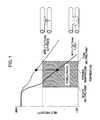
- Fig. 1 is a conceptual representation of the relationship between the forming temperature required to fuse fiber and the melt viscosity of the sheath.
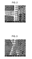
- Fig. 2 is a scanning electron micrograph of a fused fiber.
- Fig. 3 is a scanning electron micrograph of an unfused fiber.
- Fig. 4 is a schematic front sectional view of an ink reservoir according to an embodiment of the invention.
- Fig. 5 is a sectional view of an embodiment of a fiber having a core/sheath structure.
- a fibrous absorber 2 may be made of a relatively inexpensive, lightweight, recyclable olefin resin that is capable of fairly easily forming fibers, and may be made of polypropylene.
- the polypropylene mentioned herein may be any one or more of isotactic polypropylene, syndiotactic polypropylene and atactic polypropylene, unless otherwise specified.
- the fibrous absorber 2 may comprise fiber including a core 4 and a sheath 5 covering the core 4 to define an outermost layer of the fiber, thereby forming a double-layer structure.
- the core 4 may comprise a resin having a higher melting point than the resin forming the sheath 5.
- portions of the fiber can be fused to produce an absorber 2. That is, the fiber having a double-layer structure including the core and the sheath can become aggregated.
- the sheath can be melted to fuse the intersections of the fiber loops in the aggregate, and thus a fibrous absorber 2 can be produced.
- the core 4 and the sheath 5 may have a larger difference in melting point, as a smaller difference in melting point may make it difficult to control temperature.
- the core may be melted and may not maintain its own shape when the fiber is heated to form the absorber.
- the core 4 may comprise a polypropylene homopolymer, which has a higher melting point and exhibits smaller heat shrinkage than many other polypropylenes.
- the core 4 may have a melting point of 140°C or more, and even 160°C or more. If instead an ethylene-propylene random copolymer that exhibits large heat shrinkage were to be used for the core, it could occur that the resulting absorber could become very hard and have no repulsion because of the shrinkage of the fiber after forming. Such an absorber could form gaps in an ink reservoir and may cause ink to leak.
- polypropylene can be polymerized in the presence of a metallocene catalyst.
- a polypropylene that is an ethylene-propylene random copolymer having a low melting point may be used.
- the sheath 5 has a melting point of less than 140°C, and even 130°C or less.
- an ethylene-propylene random copolymer polymerized in the presence of a metallocene catalyst may be provided.
- a suitable polypropylene sheath 5 may have a melting point of less than 140°C and a melt mass-flow rate (MFR) of 7 g/10 min or more as measured at a temperature of 230°C and a load of 2.16 kg according to JIS K 7210. If the melt mass-flow rate is less than 7 g/10 min, it can occur that the fibers may not sufficiently fuse with each other, and accordingly the capillary force and the shape of the fibrous absorber may not be maintained. However, if the melt mass-flow rate is excessively high, the material may be melted to move too fast, and accordingly the capillary force and the shape of the fibrous absorber may not be maintained.
- MFR melt mass-flow rate
- the conditions for manufacturing the fibrous absorber of the ink reservoir can become strict.
- the upper limit of the melt mass-flow rate could not be determined from the experiment in the Example described later because the experiments were conducted using limited materials.
- upper limit for a suitable melt mass-flow rate is believed to be about 40 g/10 min or less. If the melt mass-flow rate is higher than this value, the material may be melted to flow faster and may become difficult to control. Consequently, the capillary force and the shape may not be maintained so as to be suitable as the fibrous absorber for the ink reservoir.
- the melt mass-flow rate (MFR) is an index representing the melt viscosity of a resin, and can be measured at a temperature of 230°C and a load of 2.16 kg according to JIS K 7210 (a Japanese Industrial Standard corresponding to ASTM D1238).
- Fig. 1 shows a conceptual representation of the relationship between the forming temperature for fusing the fiber and the melt viscosity of the sheath, illustrating a mechanism for fusing the fiber in detail.
- the horizontal axis represents temperature
- the vertical axis represents the melt viscosity of the fiber material of the sheath 5.
- the solid line shows the behavior of a sheath 5 having a higher MFR
- the dashed line shows the behavior of a sheath 5 having a lower MFR.
- sheaths having different MFRs exhibit large differences in melt viscosity at the same forming temperature.
- the sheath 5 may be heated to at least partially melt so that the melted sheath 5 flows to nearby portions of the fiber. Accordingly, the forming temperature may be equal to or more than the melting point of the sheath 5. However, if the forming temperature is also higher than the melting point of the core 4, the fiber may not maintain its own shape. Accordingly, a suitable forming temperature may be higher than the melting point of the sheath 5 and lower than the melting point of the core 4.
- the melt viscosity of the sheath 5 is also an important factor for fusing the fiber.
- a sheath 5 having an excessively high melt viscosity e.g., dashed line in Fig. 1
- the sheath 5 having a sufficiently low melt viscosity e.g., solid line in Fig. 1
- the sheath 5 flows to move to nearby portions of the fiber, and thus portions of the fiber can be fused to each other. Accordingly, the diagonally shaded area in Fig. 1 represents such a fusible range.
- melt viscosity suitable for fusion may be provided.
- Figs. 2 and 3 show actual fused and unfused states of a fiber. These figures are photographs of fibers observed by SEM.
- Fig. 2 shows a state of a fused fiber
- Fig. 3 shows a state of an unfused fiber.
- a sheath 5 having an MFR of 7 g/10 min or more can fuse and result in a fibrous absorber 2 for an ink reservoir, having a sufficient strength and capillary force. The higher the MFR, the more the fusion occurs. In contrast, when the MFR is less than 7 g/10 min, fusion may hardly occur, and the result may be the fiber state as shown in Fig. 3 .
- a fibrous absorber 2 whose fiber is not fused exhibits a low strength and an insufficient capillary force. Consequently, the resulting ink reservoir may not adequately function.
- the ratio of the sheath 5 to the core 4 is not particularly limited, it is may be about 1:1 on a weight basis.
- the sheath 5 does not contain a neutralizer because the neutralizer may leach into the ink. The residue from the metallocene catalyst may hardly cause any disadvantage, and accordingly a neutralizer may not be required.
- the sheath 5 may be made of a polypropylene polymerized in the presence of a metallocene catalyst.
- the core 4 may also optionally contain a neutralizer, such as a hydrotalcite compound, because the sheath 5 may be capable of restraining the leaching of the neutralizer from the core 4.
- the fiber having the above-described core/sheath structure may be formed in a floc.
- the intertwined fiber of the floc can be disentangled and processed into web sheets with a carding machine.
- the web sheets may be bundled together and passed through a heating roller to fuse the fibers in the bundle with each other.
- the fused fibrous absorber 2 can be cut to a predetermined length in view of the capillary force and other factors, such as after being put in a case of the ink reservoir.
- the fused fibrous absorber 2 may be capable of maintaining a shape suitable for generating a capillary force even after absorbing ink. Also, even if an external force is applied to the ink reservoir, such as vibration or drop impact during transfer or storage, or environmental changes occur, such as changes in pressure or temperature, the fibrous absorber can be secured in the ink reservoir.
- the ink retention of the fibrous absorber 2 depends on the number of crimps, the fineness and the density of the fiber of the fibrous absorber 2.
- the fibrous absorber 2 for the ink reservoir has a capillary force (such as 0 to 150 mmAq, and even 30 to 100 mmAq) such that the ink is delivered to the ink jet head and is retained in the reservoir.
- the fiber of the fibrous absorber 2 may have a crimp rate of 5 to 25 and a fineness of 0.7 to 18 deniers.
- the number of crimps is defined in JIS L 1015 as the number of crimps (fiber crinkles) for a length of 25 mm, and is obtained by counting the total peaks and troughs and dividing the number by two.
- JIS L 1015 the number of crimps (fiber crinkles) for a length of 25 mm
- the ink retention resulting from capillary action is increased as the number of crimps is increased.
- the lower the ink retention the better the efficiency in use of the ink.
- the crimp rate can be 5 to 25, and even 10 to 20.
- the fineness of the fiber can be 0.7 deniers (about 10 ⁇ m in diameter) to 18 deniers (about 50 ⁇ m in diameter).
- the space in the aggregate of the fiber becomes larger to reduce the ink retention produced by negative pressure.
- the space in the aggregate of the fiber becomes smaller to increase the ink retention.
- a fibrous absorber 2 having a density of 0.02 to 0.06 (g/cm 3 ) may be suitable to retain ink.
- the polypropylenes (e.g., the homopolymer and random copolymer) used in the present embodiment may be produced (i.e., polymerized) in the presence of a metallocene catalyst.
- a metallocene catalyst is a mixture of aluminoxane, a non-coordinating ionic compound or the like, and a compound having a structure in which a transition metal, such as titanium, iron, zirconium or hafnium, is caught in a compound having a cyclopentadienyl skeleton.
- Exemplary metallocene compounds are disclosed in, for example, Japanese Patent No.
- 4002794 include but are not limited to bis (cyclopentadienyl) zirconium dichloride, bis (indenyl) zirconium dichloride, bis (fluorenyl) zirconium dichloride, bis(azulenyl) zirconium dichloride, bis (4, 5, 6, 7-tetrahydroindenyl)zirconium dichloride, (cyclopentadienyl) (3, 4-dimethylcyclopentadienyl) zirconium dichloride, methylenebis (cyclopentadienyl) zirconium dichloride, methylene (cyclopentadienyl) (3, 4-dimethylcyclopentadienyl) zirconium dichloride, isopropylidene (cyclopentadienyl) (3, 4-dimethylcyclopentadienyl) zirconium dichloride, ethylene (cyclopentadienyl) (3, 5-dimethylpent
- the fibrous absorber can be held in a polypropylene case to form an ink reservoir.
- the ink reservoir can retain ink, and the ink reservoir containing ink may be mounted in a printer and then used.
- the invention is furthermore not limited to the following Examples, and embodiments other than those specifically described herein may also be provided.
- a polypropylene homopolymer (melting point: 165°C; MFR (hereinafter representing the melt mass-flow rate measured according to JIS K 7210): 23 g/10 min) polymerized in the presence of a Ziegler-Natta catalyst was used, and 500 ppm of a hydrotalcite compound (Mg 4.3 Al 2 (OH) 12.6 CO 3 ⁇ mH 2 O) was added as a neutralizer.
- a hydrotalcite compound Mg 4.3 Al 2 (OH) 12.6 CO 3 ⁇ mH 2 O
- an ethylene-propylene random copolymer (melting point: 125°C; MFR: 25 g/10 min) polymerized in the presence of a metallocene catalyst was used. No neutralizer was used.
- the core and the sheath were formed in a ratio of 1:1 by extrusion.
- the fiber formed in a floc was disentangled and formed into web sheets with a carding machine.
- the web sheets were bundled together, and only the sheaths were melted through a heating roller of 140°C so that the fibers were fused to form a fibrous absorber 2.
- a fibrous absorber 2 was formed in the same manner as in Example 1, except that the forming temperature of the fibrous absorber 2 was 135°C in the heating roller.
- Example 4 For the core 4, a polypropylene homopolymer (melting point: 160°C; MFR: 23 g/10 min) polymerized in the presence of a metallocene catalyst was used. No neutralizer was used. The other conditions were the same as in Example 1.
- Example 5 For the sheath 5, an ethylene-propylene random copolymer (melting point: 125°C; MFR: 7 g/10 min) polymerized in the presence of a metallocene catalyst was used. No neutralizer was used. The other conditions were the same as in Example 1.
- Comparative Example 1 a well-known fibrous absorber 2 was prepared which is formed of fiber including a polypropylene core 4 and a polyethylene sheath 5.
- a polyethylene homopolymer (melting point: 130°C; MFR: 12.5 g/10 min) polymerized in the presence of a Ziegler-Natta catalyst) was used for the sheath 5, and 500 ppm of a hydrotalcite compound (Mg 4 . 3 Al 2 (OH) 12.6 CO 3 ⁇ mH 2 O) was added as a neutralizer.
- a hydrotalcite compound Mg 4 . 3 Al 2 (OH) 12.6 CO 3 ⁇ mH 2 O
- the prepared fibrous absorber 2 was cut out into a piece of 5 mm by 5 mm. After platinum vapor deposition, it was observed by scanning electron microscopy (SEM) whether or not the fibers were fused. A fused sample was observed as shown in Fig. 2 , and unfused sample was observed as shown in Fig. 3 . The results are shown in Table 1. In Examples 1 to 4, fusion was observed at 10 to several tens of points in the area of 5 mm x 5 mm, and thus the fusion equivalent to that in Comparative Example 1 was observed. In Example 4, the fusion was in substantially the same state as in Examples 1 to 3, but the number of fused points was slightly smaller.
- the fibrous absorber 2 of Comparative Example 2 was not fused, and when it was placed in the ink reservoir and retained ink, the fibrous absorber 2 shrunk and did not maintain a predetermined shape and capillary force for the fibrous absorber 2 of the ink reservoir.
- the fibrous absorbers 2 of Examples 1 to 4 maintained the predetermined shape for use in the ink reservoir.
- the fibrous absorber 2 of Comparative Example 3 became seriously shrunken after being formed, and thus the predetermined shape for use in the ink reservoir was not formed. Without being limited to any theory, this may be because the core 4 was made of random polypropylene, and, after forming, the stress relaxation of the fiber caused the fiber to shrink.
- the results of Comparative Example 3 suggest that a less shrinkable homopolymer may be suitable as the material of the core 4.
- the resulting fibrous absorber 2 was immersed in a test ink and heated to 100°C for 10 hours in a PCT (pressure cooker tester). After cooling to room temperature, the amount of Al leached into the test ink was measured by ICP. The amount of leached Al was compared among the fibrous absorbers of Examples 1 and comparative Examples 1 to 3, which were formed under the same conditions. The results are shown in the Table 1.
- PP represents a polypropylene resin
- PE represents a polyethylene resin.
- the possibility of recycling the fibrous absorbers prepared in Examples 1 to 4 and Comparative Example 1, to obtain a recycled material are shown in the Table 1.
- the fibrous absorber was cut into pieces of a predetermined size. After being washed and dried, the pieces of the fibrous absorber were formed into pellets. The pellets were recycled into a case of an ink reservoir by injection molding.
- the case recycled from the fibrous absorber of Comparative Example 1 exhibited a considerably degraded heat resistance and strength, and was unsuitable for the ink reservoir. Without being limited to any particular theory, this may be because hybrids of PP and PE have a lower heat resistance and strength than simple PP, and because phase separation between PP and PE may affect such properties.
- the cases recycled from the fibrous absorbers of Examples 1 to 4 exhibited relatively favorable heat resistances and strengths, and were suitable for the ink reservoir.
- waste ink reservoirs can be recycled into, for example, a polypropylene material for the case of an ink reservoir, by being collected and applying a recycling process to the collected ink reservoirs having the fibrous absorber contained therein.
- an ink reservoir can be provided containing a recyclable fibrous absorber that is made of a fiber material produced in a process limiting the use of neutralizer, including a core and a sheath made of materials of the same type.
- the examples further show that by forming the core of a high-melting point polypropylene homopolymer, and forming the sheath of a low-melting point ethylene-propylene random copolymer, the double-layer core/sheath structure can be formed of only polypropylene.
- an ethylene-propylene random copolymer polymerized in the presence of a metallocene catalyst can be provided have the same melting point as a polyethylene.
- the metallocene catalyst contains scarcely any metal-corrosive chlorine, and does not require the use of neutralizer for producing a fiber material.
- an ink reservoir prepared according to the examples is recyclable and environmentally friendly.
- the ink reservoir has a reduced likelihood of causing failure in printing caused by a neutralizer.
- An ink reservoir capable of retaining ink includes a case having a polypropylene, and a fibrous absorber (2) contained in the case, the fibrous absorber having an aggregate of fiber with a double-layer structure including a core (4) and a sheath (5), the sheath being fused at intersections of fiber loops.
- the core has a polypropylene homopolymer having a melting point of 140°C or more
- the sheath has an ethylene-propylene random copolymer having a melting point of less than 140°C and a melt mass-flow rate of 7 g/10 min or more as measured at 230°C and a load of 2.16 kg according to JIS K 7210.
Landscapes
- Nonwoven Fabrics (AREA)
- Multicomponent Fibers (AREA)
- Ink Jet (AREA)
Claims (4)
- Réservoir d'encre pouvant contenir de l'encre, comprenant :un boîtier comprenant un polypropylène ; etun élément absorbeur fibreux (2) contenu dans le boîtier, l'élément absorbeur fibreux comprenant un agrégat de fibre présentant une structure à double couche comprenant une âme (4) et une gaine (5), la gaine étant fondue à des intersections de boucles de fibres,l'âme comprenant un homopolymère de polypropylène ayant un point de fusion supérieur ou égal à 140 °C, et la gaine comprenant un copolymère aléatoire éthylène-propylène ayant un point de fusion inférieur à 140°C et un débit de masse fondue supérieur ou égal à 7 g/10 min tel que mesuré à 230°C et une charge de 2,16 kg selon JIS K 7210.
- Réservoir d'encre selon la revendication 1, dans lequel le copolymère aléatoire éthylène-propylène de la gaine est polymérisé en la présence d'un catalyseur de métallocène.
- Réservoir d'encre selon la revendication 1, dans lequel la fibre de l'élément absorbeur fibreux a une finesse de 0,7 à 18 deniers et un taux de frisure de 5 à 25, et l'élément absorbeur fibreux a une force capillaire inférieure ou égale à 150 mmAq.
- Réservoir d'encre selon la revendication 1, dans lequel le réservoir d'encre peut être recyclé en un matériau de polypropylène en étant fondu avec l'élément absorbeur fibreux contenu en son sein.
Applications Claiming Priority (1)
| Application Number | Priority Date | Filing Date | Title |
|---|---|---|---|
| JP2008135686A JP5094555B2 (ja) | 2008-05-23 | 2008-05-23 | インクタンク |
Publications (3)
| Publication Number | Publication Date |
|---|---|
| EP2123459A2 EP2123459A2 (fr) | 2009-11-25 |
| EP2123459A3 EP2123459A3 (fr) | 2010-09-22 |
| EP2123459B1 true EP2123459B1 (fr) | 2012-06-06 |
Family
ID=40908634
Family Applications (1)
| Application Number | Title | Priority Date | Filing Date |
|---|---|---|---|
| EP09159415A Not-in-force EP2123459B1 (fr) | 2008-05-23 | 2009-05-05 | Réservoir d'encre |
Country Status (3)
| Country | Link |
|---|---|
| US (1) | US20090290004A1 (fr) |
| EP (1) | EP2123459B1 (fr) |
| JP (1) | JP5094555B2 (fr) |
Families Citing this family (13)
| Publication number | Priority date | Publication date | Assignee | Title |
|---|---|---|---|---|
| US20140183125A1 (en) * | 2012-12-27 | 2014-07-03 | Seiko Epson Corporation | Liquid absorber, liquid absorption tank, and electrical machine |
| JP6468087B2 (ja) | 2014-06-23 | 2019-02-13 | セイコーエプソン株式会社 | 液体収容容器 |
| JP2019055600A (ja) * | 2014-06-23 | 2019-04-11 | セイコーエプソン株式会社 | 液体収容容器 |
| WO2017119049A1 (fr) | 2016-01-05 | 2017-07-13 | キヤノン株式会社 | Procédé d'enregistrement à jet d'encre |
| WO2017119048A1 (fr) | 2016-01-05 | 2017-07-13 | キヤノン株式会社 | Appareil d'enregistrement à jet d'encre et procédé d'enregistrement à jet d'encre |
| WO2017119046A1 (fr) | 2016-01-05 | 2017-07-13 | キヤノン株式会社 | Procédé d'enregistrement à jet d'encre |
| EP3401100A4 (fr) | 2016-01-05 | 2019-08-21 | C/o Canon Kabushiki Kaisha | Dispositif ainsi que procédé d'enregistrement à jet d'encre |
| WO2017119047A1 (fr) | 2016-01-05 | 2017-07-13 | キヤノン株式会社 | Procédé d'enregistrement et appareil d'enregistrement |
| WO2017119044A1 (fr) | 2016-01-05 | 2017-07-13 | キヤノン株式会社 | Dispositif d'enregistrement à jet d'encre |
| EP3401102B1 (fr) | 2016-01-05 | 2020-09-16 | C/o Canon Kabushiki Kaisha | Dispositif d'enregistrement à jet d'encre, et procédé de fabrication de corps poreux |
| BR112018013641A2 (pt) | 2016-01-05 | 2019-01-22 | Canon Kk | aparelho de gravação a jato de tinta e método de gravação a jato de tinta |
| WO2017131072A1 (fr) | 2016-01-29 | 2017-08-03 | キヤノン株式会社 | Appareil d'impression à jet d'encre |
| KR102842967B1 (ko) * | 2019-07-10 | 2025-08-05 | 현대자동차주식회사 | 경제형 흡기필터 및 이의 제조방법 |
Family Cites Families (27)
| Publication number | Priority date | Publication date | Assignee | Title |
|---|---|---|---|---|
| DK245488D0 (da) * | 1988-05-05 | 1988-05-05 | Danaklon As | Syntetisk fiber samt fremgangsmaade til fremstilling deraf |
| JPH042794A (ja) | 1990-04-20 | 1992-01-07 | Idemitsu Kosan Co Ltd | 硫化水素から水素を回収する方法 |
| DE69331791T2 (de) | 1993-07-20 | 2002-10-10 | Canon K.K., Tokio/Tokyo | Tintenstrahlaufzeichnungsgerät, welches eine Farbkartusche mit einem tinteninduzierenden Element verwendet |
| JP3110597B2 (ja) * | 1993-11-29 | 2000-11-20 | キヤノン株式会社 | インクジェットタンク用インク供給部材、それを有するインクカートリッジ、インクジェットユニットおよびインクジェット記録装置 |
| JP3212242B2 (ja) * | 1995-11-02 | 2001-09-25 | キヤノン株式会社 | インク保持体、インクタンク、インクジェットカートリッジ、およびプリント装置 |
| WO1997020869A1 (fr) * | 1995-12-01 | 1997-06-12 | Chisso Corporation | Articles en resine moulee |
| JP3399279B2 (ja) * | 1997-02-25 | 2003-04-21 | トヨタ車体株式会社 | 車両用防音材 |
| JPH1161637A (ja) * | 1997-08-18 | 1999-03-05 | Canon Inc | 繊維素材及びそのインク接液部材としての用途並びにこれらの製造方法 |
| JP3459793B2 (ja) * | 1998-06-26 | 2003-10-27 | キヤノン株式会社 | 吸収体及び該吸収体を用いたインクジェット用記録液収納容器 |
| US6485136B1 (en) | 1998-06-26 | 2002-11-26 | Canon Kabushiki Kaisha | Absorber and container for ink jet recording liquid using such absorber |
| US6274237B1 (en) * | 1999-05-21 | 2001-08-14 | Chisso Corporation | Potentially crimpable composite fiber and a non-woven fabric using the same |
| JP4943599B2 (ja) * | 2001-08-09 | 2012-05-30 | セイコーエプソン株式会社 | インクジェット記録装置用樹脂製フィルター |
| US20040038612A1 (en) * | 2002-08-21 | 2004-02-26 | Kimberly-Clark Worldwide, Inc. | Multi-component fibers and non-woven webs made therefrom |
| JP4081338B2 (ja) * | 2002-10-08 | 2008-04-23 | 三菱レイヨン株式会社 | ポリプロピレン系流体撹乱加工繊維及びその製造方法 |
| JP2004131869A (ja) * | 2002-10-10 | 2004-04-30 | Mitsubishi Rayon Co Ltd | 難燃性を有するポリプロピレン系熱接着性複合繊維及びその製造方法 |
| JP2004161850A (ja) * | 2002-11-12 | 2004-06-10 | Mitsubishi Rayon Co Ltd | 難燃性シート状物 |
| JP2004174920A (ja) | 2002-11-27 | 2004-06-24 | Canon Inc | インクジェット記録装置 |
| JP4351893B2 (ja) * | 2003-10-22 | 2009-10-28 | 三菱レイヨン株式会社 | ポリプロピレン系混繊捲縮糸及びその製造方法並びにカーペット |
| JP2005171169A (ja) * | 2003-12-15 | 2005-06-30 | Mitsui Chemicals Inc | ポリプロピレン樹脂組成物 |
| BRPI0507127A (pt) * | 2004-01-26 | 2007-06-19 | Procter & Gamble | fibras e não-tecidos compreendendo blendas e misturas de polipropileno |
| JP4137010B2 (ja) * | 2004-06-11 | 2008-08-20 | キヤノン株式会社 | インクジェット記録装置に用いる液体収納容器 |
| JP2006130700A (ja) * | 2004-11-02 | 2006-05-25 | Canon Inc | 負圧発生部材の挿入方法、および、それが用いられる液体収容容器 |
| JP2006248159A (ja) * | 2005-03-14 | 2006-09-21 | Seiko Epson Corp | インクカートリッジおよびその製造方法 |
| US20060216506A1 (en) * | 2005-03-22 | 2006-09-28 | Jian Xiang | Multicomponent fibers having elastomeric components and bonded structures formed therefrom |
| JP4546866B2 (ja) * | 2005-03-31 | 2010-09-22 | 三菱レイヨン株式会社 | 難燃性ポリオレフィン織編物及び難燃性繊維成形品 |
| JP4662827B2 (ja) * | 2005-08-22 | 2011-03-30 | 富士フイルム株式会社 | インクとインク接液部材を含むインクユニット |
| JP2007152839A (ja) * | 2005-12-07 | 2007-06-21 | Canon Inc | 液体収納容器 |
-
2008
- 2008-05-23 JP JP2008135686A patent/JP5094555B2/ja not_active Expired - Fee Related
-
2009
- 2009-05-05 EP EP09159415A patent/EP2123459B1/fr not_active Not-in-force
- 2009-05-21 US US12/470,410 patent/US20090290004A1/en not_active Abandoned
Also Published As
| Publication number | Publication date |
|---|---|
| JP5094555B2 (ja) | 2012-12-12 |
| EP2123459A3 (fr) | 2010-09-22 |
| US20090290004A1 (en) | 2009-11-26 |
| JP2009279872A (ja) | 2009-12-03 |
| EP2123459A2 (fr) | 2009-11-25 |
Similar Documents
| Publication | Publication Date | Title |
|---|---|---|
| EP2123459B1 (fr) | Réservoir d'encre | |
| KR101605933B1 (ko) | 해도 복합 섬유, 극세 섬유 및 복합 구금 | |
| KR102116776B1 (ko) | 혼섬 부직포 및 그 제조 방법 | |
| EP0691207B1 (fr) | Réservoir d'encre, tête d'enregistrement à jet d'encre le comportant, dispositif à jet d'encre utilisant ce réservoir d'encre et procédé de fabrication de ce réservoir d'encre | |
| EP2452737B1 (fr) | Matériau pour filtre à air constitué d'un non-tissé multicouche de type électret | |
| KR101259968B1 (ko) | 저온 가공성을 가지는 복합 섬유, 이것을 사용한 부직포 및 성형체 | |
| EP2111490B1 (fr) | Fibre pour tissu nontissé par voie humide | |
| EP3666360B2 (fr) | Utilisation des fibres bicomposantes comprenant des plastiques recyclés | |
| WO1988010330A1 (fr) | Fibres de polypropylene reticulees, procede de production et tissu non tisse en fibres reticulees | |
| CN102037174A (zh) | 气纺不织布制造用复合纤维以及高密度气纺不织布的制造方法 | |
| US20230339171A1 (en) | Process of manufacturing reticulated foam products, using alternative materials | |
| JP2002212311A (ja) | 炭素繊維強化スタンパブルシート、その製造方法、及びその成形品 | |
| US6737372B2 (en) | Powders-affixed nonwoven fabric, process for manufacturing same, and sheet material containing same | |
| US20230366130A1 (en) | Low leachable fibers and fiber structure | |
| JP5636987B2 (ja) | 濾材及びその製造方法 | |
| US20240239984A1 (en) | Method for producing resin for recycling | |
| JP5341439B2 (ja) | 液吸収体用繊維素材およびその製造方法 | |
| US20220145528A1 (en) | Method for producing opened carbon fibre bundle and fibre reinforced composite material | |
| WO2020202899A1 (fr) | Tissu non tissé produit par extrusion-soufflage pour filtre à liquide, corps stratifié dudit tissu non tissé produit par extrusion-soufflage, et filtre à liquide équipé du corps stratifié | |
| JP3131217B2 (ja) | 精密濾過用円筒状フィルター | |
| JP7247433B2 (ja) | 再生ポリエステル樹脂及び再生ポリエステル樹脂の製造方法 | |
| JP6173670B2 (ja) | フィルターおよびその製造方法 | |
| KR20230028580A (ko) | 멜트블로우 부직포 및 이를 포함하는 필터 | |
| JP4267436B2 (ja) | 血漿又は血清用フィルタの製造方法 | |
| CN117136128A (zh) | 再生用树脂的制造方法 |
Legal Events
| Date | Code | Title | Description |
|---|---|---|---|
| PUAI | Public reference made under article 153(3) epc to a published international application that has entered the european phase |
Free format text: ORIGINAL CODE: 0009012 |
|
| AK | Designated contracting states |
Kind code of ref document: A2 Designated state(s): AT BE BG CH CY CZ DE DK EE ES FI FR GB GR HR HU IE IS IT LI LT LU LV MC MK MT NL NO PL PT RO SE SI SK TR |
|
| PUAL | Search report despatched |
Free format text: ORIGINAL CODE: 0009013 |
|
| AK | Designated contracting states |
Kind code of ref document: A3 Designated state(s): AT BE BG CH CY CZ DE DK EE ES FI FR GB GR HR HU IE IS IT LI LT LU LV MC MK MT NL NO PL PT RO SE SI SK TR |
|
| 17P | Request for examination filed |
Effective date: 20110322 |
|
| GRAP | Despatch of communication of intention to grant a patent |
Free format text: ORIGINAL CODE: EPIDOSNIGR1 |
|
| GRAS | Grant fee paid |
Free format text: ORIGINAL CODE: EPIDOSNIGR3 |
|
| GRAA | (expected) grant |
Free format text: ORIGINAL CODE: 0009210 |
|
| AK | Designated contracting states |
Kind code of ref document: B1 Designated state(s): AT BE BG CH CY CZ DE DK EE ES FI FR GB GR HR HU IE IS IT LI LT LU LV MC MK MT NL NO PL PT RO SE SI SK TR |
|
| REG | Reference to a national code |
Ref country code: GB Ref legal event code: FG4D |
|
| REG | Reference to a national code |
Ref country code: AT Ref legal event code: REF Ref document number: 560815 Country of ref document: AT Kind code of ref document: T Effective date: 20120615 Ref country code: CH Ref legal event code: EP |
|
| REG | Reference to a national code |
Ref country code: IE Ref legal event code: FG4D |
|
| REG | Reference to a national code |
Ref country code: DE Ref legal event code: R096 Ref document number: 602009007426 Country of ref document: DE Effective date: 20120809 |
|
| REG | Reference to a national code |
Ref country code: NL Ref legal event code: VDEP Effective date: 20120606 |
|
| PG25 | Lapsed in a contracting state [announced via postgrant information from national office to epo] |
Ref country code: LT Free format text: LAPSE BECAUSE OF FAILURE TO SUBMIT A TRANSLATION OF THE DESCRIPTION OR TO PAY THE FEE WITHIN THE PRESCRIBED TIME-LIMIT Effective date: 20120606 Ref country code: CY Free format text: LAPSE BECAUSE OF FAILURE TO SUBMIT A TRANSLATION OF THE DESCRIPTION OR TO PAY THE FEE WITHIN THE PRESCRIBED TIME-LIMIT Effective date: 20120606 Ref country code: FI Free format text: LAPSE BECAUSE OF FAILURE TO SUBMIT A TRANSLATION OF THE DESCRIPTION OR TO PAY THE FEE WITHIN THE PRESCRIBED TIME-LIMIT Effective date: 20120606 Ref country code: NO Free format text: LAPSE BECAUSE OF FAILURE TO SUBMIT A TRANSLATION OF THE DESCRIPTION OR TO PAY THE FEE WITHIN THE PRESCRIBED TIME-LIMIT Effective date: 20120906 Ref country code: SE Free format text: LAPSE BECAUSE OF FAILURE TO SUBMIT A TRANSLATION OF THE DESCRIPTION OR TO PAY THE FEE WITHIN THE PRESCRIBED TIME-LIMIT Effective date: 20120606 |
|
| REG | Reference to a national code |
Ref country code: AT Ref legal event code: MK05 Ref document number: 560815 Country of ref document: AT Kind code of ref document: T Effective date: 20120606 |
|
| REG | Reference to a national code |
Ref country code: LT Ref legal event code: MG4D Effective date: 20120606 |
|
| PG25 | Lapsed in a contracting state [announced via postgrant information from national office to epo] |
Ref country code: HR Free format text: LAPSE BECAUSE OF FAILURE TO SUBMIT A TRANSLATION OF THE DESCRIPTION OR TO PAY THE FEE WITHIN THE PRESCRIBED TIME-LIMIT Effective date: 20120606 Ref country code: LV Free format text: LAPSE BECAUSE OF FAILURE TO SUBMIT A TRANSLATION OF THE DESCRIPTION OR TO PAY THE FEE WITHIN THE PRESCRIBED TIME-LIMIT Effective date: 20120606 Ref country code: SI Free format text: LAPSE BECAUSE OF FAILURE TO SUBMIT A TRANSLATION OF THE DESCRIPTION OR TO PAY THE FEE WITHIN THE PRESCRIBED TIME-LIMIT Effective date: 20120606 Ref country code: GR Free format text: LAPSE BECAUSE OF FAILURE TO SUBMIT A TRANSLATION OF THE DESCRIPTION OR TO PAY THE FEE WITHIN THE PRESCRIBED TIME-LIMIT Effective date: 20120907 |
|
| PG25 | Lapsed in a contracting state [announced via postgrant information from national office to epo] |
Ref country code: SK Free format text: LAPSE BECAUSE OF FAILURE TO SUBMIT A TRANSLATION OF THE DESCRIPTION OR TO PAY THE FEE WITHIN THE PRESCRIBED TIME-LIMIT Effective date: 20120606 Ref country code: EE Free format text: LAPSE BECAUSE OF FAILURE TO SUBMIT A TRANSLATION OF THE DESCRIPTION OR TO PAY THE FEE WITHIN THE PRESCRIBED TIME-LIMIT Effective date: 20120606 Ref country code: AT Free format text: LAPSE BECAUSE OF FAILURE TO SUBMIT A TRANSLATION OF THE DESCRIPTION OR TO PAY THE FEE WITHIN THE PRESCRIBED TIME-LIMIT Effective date: 20120606 Ref country code: CZ Free format text: LAPSE BECAUSE OF FAILURE TO SUBMIT A TRANSLATION OF THE DESCRIPTION OR TO PAY THE FEE WITHIN THE PRESCRIBED TIME-LIMIT Effective date: 20120606 Ref country code: RO Free format text: LAPSE BECAUSE OF FAILURE TO SUBMIT A TRANSLATION OF THE DESCRIPTION OR TO PAY THE FEE WITHIN THE PRESCRIBED TIME-LIMIT Effective date: 20120606 Ref country code: NL Free format text: LAPSE BECAUSE OF FAILURE TO SUBMIT A TRANSLATION OF THE DESCRIPTION OR TO PAY THE FEE WITHIN THE PRESCRIBED TIME-LIMIT Effective date: 20120606 Ref country code: BE Free format text: LAPSE BECAUSE OF FAILURE TO SUBMIT A TRANSLATION OF THE DESCRIPTION OR TO PAY THE FEE WITHIN THE PRESCRIBED TIME-LIMIT Effective date: 20120606 Ref country code: IS Free format text: LAPSE BECAUSE OF FAILURE TO SUBMIT A TRANSLATION OF THE DESCRIPTION OR TO PAY THE FEE WITHIN THE PRESCRIBED TIME-LIMIT Effective date: 20121006 |
|
| PG25 | Lapsed in a contracting state [announced via postgrant information from national office to epo] |
Ref country code: PT Free format text: LAPSE BECAUSE OF FAILURE TO SUBMIT A TRANSLATION OF THE DESCRIPTION OR TO PAY THE FEE WITHIN THE PRESCRIBED TIME-LIMIT Effective date: 20121008 Ref country code: PL Free format text: LAPSE BECAUSE OF FAILURE TO SUBMIT A TRANSLATION OF THE DESCRIPTION OR TO PAY THE FEE WITHIN THE PRESCRIBED TIME-LIMIT Effective date: 20120606 Ref country code: IT Free format text: LAPSE BECAUSE OF FAILURE TO SUBMIT A TRANSLATION OF THE DESCRIPTION OR TO PAY THE FEE WITHIN THE PRESCRIBED TIME-LIMIT Effective date: 20120606 |
|
| PLBE | No opposition filed within time limit |
Free format text: ORIGINAL CODE: 0009261 |
|
| STAA | Information on the status of an ep patent application or granted ep patent |
Free format text: STATUS: NO OPPOSITION FILED WITHIN TIME LIMIT |
|
| PG25 | Lapsed in a contracting state [announced via postgrant information from national office to epo] |
Ref country code: DK Free format text: LAPSE BECAUSE OF FAILURE TO SUBMIT A TRANSLATION OF THE DESCRIPTION OR TO PAY THE FEE WITHIN THE PRESCRIBED TIME-LIMIT Effective date: 20120606 Ref country code: ES Free format text: LAPSE BECAUSE OF FAILURE TO SUBMIT A TRANSLATION OF THE DESCRIPTION OR TO PAY THE FEE WITHIN THE PRESCRIBED TIME-LIMIT Effective date: 20120917 |
|
| 26N | No opposition filed |
Effective date: 20130307 |
|
| REG | Reference to a national code |
Ref country code: DE Ref legal event code: R097 Ref document number: 602009007426 Country of ref document: DE Effective date: 20130307 |
|
| PG25 | Lapsed in a contracting state [announced via postgrant information from national office to epo] |
Ref country code: BG Free format text: LAPSE BECAUSE OF FAILURE TO SUBMIT A TRANSLATION OF THE DESCRIPTION OR TO PAY THE FEE WITHIN THE PRESCRIBED TIME-LIMIT Effective date: 20120906 |
|
| PG25 | Lapsed in a contracting state [announced via postgrant information from national office to epo] |
Ref country code: MC Free format text: LAPSE BECAUSE OF FAILURE TO SUBMIT A TRANSLATION OF THE DESCRIPTION OR TO PAY THE FEE WITHIN THE PRESCRIBED TIME-LIMIT Effective date: 20120606 |
|
| REG | Reference to a national code |
Ref country code: CH Ref legal event code: PL |
|
| GBPC | Gb: european patent ceased through non-payment of renewal fee |
Effective date: 20130505 |
|
| PG25 | Lapsed in a contracting state [announced via postgrant information from national office to epo] |
Ref country code: CH Free format text: LAPSE BECAUSE OF NON-PAYMENT OF DUE FEES Effective date: 20130531 Ref country code: LI Free format text: LAPSE BECAUSE OF NON-PAYMENT OF DUE FEES Effective date: 20130531 |
|
| REG | Reference to a national code |
Ref country code: IE Ref legal event code: MM4A |
|
| REG | Reference to a national code |
Ref country code: FR Ref legal event code: ST Effective date: 20140131 |
|
| PG25 | Lapsed in a contracting state [announced via postgrant information from national office to epo] |
Ref country code: GB Free format text: LAPSE BECAUSE OF NON-PAYMENT OF DUE FEES Effective date: 20130505 Ref country code: IE Free format text: LAPSE BECAUSE OF NON-PAYMENT OF DUE FEES Effective date: 20130505 |
|
| PG25 | Lapsed in a contracting state [announced via postgrant information from national office to epo] |
Ref country code: FR Free format text: LAPSE BECAUSE OF NON-PAYMENT OF DUE FEES Effective date: 20130531 |
|
| PGFP | Annual fee paid to national office [announced via postgrant information from national office to epo] |
Ref country code: DE Payment date: 20140531 Year of fee payment: 6 |
|
| PG25 | Lapsed in a contracting state [announced via postgrant information from national office to epo] |
Ref country code: MT Free format text: LAPSE BECAUSE OF FAILURE TO SUBMIT A TRANSLATION OF THE DESCRIPTION OR TO PAY THE FEE WITHIN THE PRESCRIBED TIME-LIMIT Effective date: 20120606 |
|
| PG25 | Lapsed in a contracting state [announced via postgrant information from national office to epo] |
Ref country code: TR Free format text: LAPSE BECAUSE OF FAILURE TO SUBMIT A TRANSLATION OF THE DESCRIPTION OR TO PAY THE FEE WITHIN THE PRESCRIBED TIME-LIMIT Effective date: 20120606 |
|
| PG25 | Lapsed in a contracting state [announced via postgrant information from national office to epo] |
Ref country code: LU Free format text: LAPSE BECAUSE OF NON-PAYMENT OF DUE FEES Effective date: 20130505 Ref country code: HU Free format text: LAPSE BECAUSE OF FAILURE TO SUBMIT A TRANSLATION OF THE DESCRIPTION OR TO PAY THE FEE WITHIN THE PRESCRIBED TIME-LIMIT; INVALID AB INITIO Effective date: 20090505 Ref country code: MK Free format text: LAPSE BECAUSE OF FAILURE TO SUBMIT A TRANSLATION OF THE DESCRIPTION OR TO PAY THE FEE WITHIN THE PRESCRIBED TIME-LIMIT Effective date: 20120606 |
|
| REG | Reference to a national code |
Ref country code: DE Ref legal event code: R119 Ref document number: 602009007426 Country of ref document: DE |
|
| PG25 | Lapsed in a contracting state [announced via postgrant information from national office to epo] |
Ref country code: DE Free format text: LAPSE BECAUSE OF NON-PAYMENT OF DUE FEES Effective date: 20151201 |