EP2123902A1 - Verfahren und Vorrichtung zum Steuern von Glühstiften in einem Dieselmotor, insbesondere für Motorfahrzeuge - Google Patents
Verfahren und Vorrichtung zum Steuern von Glühstiften in einem Dieselmotor, insbesondere für Motorfahrzeuge Download PDFInfo
- Publication number
- EP2123902A1 EP2123902A1 EP08009375A EP08009375A EP2123902A1 EP 2123902 A1 EP2123902 A1 EP 2123902A1 EP 08009375 A EP08009375 A EP 08009375A EP 08009375 A EP08009375 A EP 08009375A EP 2123902 A1 EP2123902 A1 EP 2123902A1
- Authority
- EP
- European Patent Office
- Prior art keywords
- voltage
- current
- error
- calculating
- function
- Prior art date
- Legal status (The legal status is an assumption and is not a legal conclusion. Google has not performed a legal analysis and makes no representation as to the accuracy of the status listed.)
- Granted
Links
Images

Classifications
-
- F—MECHANICAL ENGINEERING; LIGHTING; HEATING; WEAPONS; BLASTING
- F02—COMBUSTION ENGINES; HOT-GAS OR COMBUSTION-PRODUCT ENGINE PLANTS
- F02P—IGNITION, OTHER THAN COMPRESSION IGNITION, FOR INTERNAL-COMBUSTION ENGINES; TESTING OF IGNITION TIMING IN COMPRESSION-IGNITION ENGINES
- F02P19/00—Incandescent ignition, e.g. during starting of internal combustion engines; Combination of incandescent and spark ignition
- F02P19/02—Incandescent ignition, e.g. during starting of internal combustion engines; Combination of incandescent and spark ignition electric, e.g. layout of circuits of apparatus having glowing plugs
- F02P19/021—Incandescent ignition, e.g. during starting of internal combustion engines; Combination of incandescent and spark ignition electric, e.g. layout of circuits of apparatus having glowing plugs characterised by power delivery controls
- F02P19/023—Individual control of the glow plugs
-
- F—MECHANICAL ENGINEERING; LIGHTING; HEATING; WEAPONS; BLASTING
- F02—COMBUSTION ENGINES; HOT-GAS OR COMBUSTION-PRODUCT ENGINE PLANTS
- F02P—IGNITION, OTHER THAN COMPRESSION IGNITION, FOR INTERNAL-COMBUSTION ENGINES; TESTING OF IGNITION TIMING IN COMPRESSION-IGNITION ENGINES
- F02P19/00—Incandescent ignition, e.g. during starting of internal combustion engines; Combination of incandescent and spark ignition
- F02P19/02—Incandescent ignition, e.g. during starting of internal combustion engines; Combination of incandescent and spark ignition electric, e.g. layout of circuits of apparatus having glowing plugs
- F02P19/021—Incandescent ignition, e.g. during starting of internal combustion engines; Combination of incandescent and spark ignition electric, e.g. layout of circuits of apparatus having glowing plugs characterised by power delivery controls
- F02P19/022—Incandescent ignition, e.g. during starting of internal combustion engines; Combination of incandescent and spark ignition electric, e.g. layout of circuits of apparatus having glowing plugs characterised by power delivery controls using intermittent current supply
Definitions
- the present invention relates to a method and an apparatus for controlling glow plugs in a Diesel engine, particularly for motor-vehicles, of the kinds defined in the preambles of claims 1 and 6, respectively.
- Glow plugs are typically associated with the cylinder chambers of Diesel engines, and are controlled by an associated electronic control module which is arranged to control in real time the amount of energy transferred to each glow plug, so as to reach and hold a predetermined working temperature.
- the glowing control apparatus comprises also electrical connections between a vehicle voltage supply, such as the battery of the vehicle, the glow plugs and the electronic control module.
- the electronic control module drives the electronic switches, generally MOSFET transistors, by means of pulse-width-modulated (PWM) control signals.
- PWM pulse-width-modulated
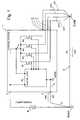
- Figure 1 is an electric diagram showing an apparatus for controlling glow plugs in a Diesel engine.
- reference numeral 10 generally indicates an electronic control system for driving the glow plugs GP1, GP2, GP3 and GP4 associated each with a respective cylinder chamber in a 4-cylinder Diesel internal combustion engine.
- the glow plugs GP1-GP4 are connected each between a respective output terminal 1-4 of the electronic control system 10 and a ground terminal EGND ("engine ground").
- voltage supply B such as the battery of the motor-vehicle, has its positive terminal connected to a supply input 5 of the electronic control system 10, and the negative terminal connected to a ground terminal BGND ("battery ground").
- the ground terminal BGND is connected to the ground terminal EGND by a conductor 6, and is further connected to a terminal 7 of the electronic control system 10 through a conductor 8.
- the terminal 7 of the electronic control system is connected to an "internal ground" terminal IGND of the electronic control system 10, through a conductor 9.
- the electronic control system 10 comprises four electronic switches M1-M4, having each the drain-source path connected essentially in series with a respective glow plug, between the terminals of the voltage supply B.
- the electronic switches M1-M4 are, for instance, MOSFET transistors, and have their gates connected to respective outputs of a control unit 20.
- the control unit 20 drives said switches M1-M4 in order to realize a PWM control.
- the control system 10 has a node A which is used to measure, in a known manner, the voltage across the glow plugs GP1-GP4.
- the glowing control system 10 above disclosed has many disadvantages:
- the energy transferred to the glow plugs GP1-GP4 is the key variable to be controlled, and conventional glow-plug control systems generally monitor both the voltage across each glow plug and the current flowing through each glow plug.
- Controlling the energy transferred to the glow plugs GP1-GP4 means controlling the power transferred thereto during each period of the PWM driving signals applied to the corresponding electronic switches M1-M4.
- the duty-cycle of the PWM driving signals is controlled in a closed-loop, in order to supply the desired energy to each glow plug GP1-GP4.
- the control unit 20 defines a voltage duty factor that must be applied to each glow plug GP1-GP4.
- the control unit 20 performs a voltage closed loop control by monitoring the supply voltage B at the node A.
- the voltage duty factor is a function of said monitored voltage.
- the PWM signals generated by the control unit 20 depend on the difference between the voltage at the node A and the potential at the "internal ground” terminal IGND, whereas the heating power generated in each glow plug GP1-GP4 is a function of the voltage at the node A and the potential present at the "engine ground” terminal EGND of the glow plugs GP1-GP4.
- control unit 20 defines a current duty factor for each glow plug GP1-GP4.
- the control unit 20 performs a current closed loop control by monitoring the current flowing through the glow plugs GP1-GP4.
- the current duty factor is a function of said monitored current.
- the main idea of the present invention is to identify a state variable which is not influenced by the resistive path and ground shifts between the control unit 20 and glow plugs GP1-GP4. Even if the current control method has brought good results for certain heating points, it shows low accuracies of the controlled temperature, mainly due to the electrothermal characteristics of the components.
- glow plug resistance can have a not negligible spread which affects the temperature.
- the known voltage control minimizes the resistance spread effect on the temperature regulation, but the performances result heavily affected by the series voltage drops.
- the known current control rejects the series voltage drops, but the temperature regulation results heavily affected by the resistance spread effect.
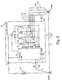
- Figure 2 is an electric diagram showing an apparatus for controlling glow plugs in a Diesel engine according to the invention. Similar elements to those shown in figure 1 have the same reference numeral.
- the unit 20 has a first series of four inputs which are connected each to a respective one of the terminals 1-4, to provide said unit with an analogue signal representative of the voltage across the corresponding glow plugs GP1-GP4. Alternatively, it is possible to use the voltage measured at node A.
- the unit 20 has a second series of four inputs, which are connected each to a respective current-sensing means S1-S4, such as a shunt resistor, to provide said unit 20 with signals representative of the current flowing in the operation through each of the glow plugs GP1-GP4.
- a respective current-sensing means S1-S4 such as a shunt resistor
- the current-sensing means S1-S4 are arranged between the electronic switches M1-M4 and the glow plugs GP1-GP4.
- the said sensors could be arranged between the electronic switches M1-M4 and the positive terminal of the voltage supply B.
- ⁇ I I * - I ⁇ I *
- I* is a current setpoint calculated as a voltage setpoint V*, such as the battery voltage, divided by the nominal glow plug resistance
- ⁇ is the current measured by the current-sensing means S1-S4.
- the K-function provides a value within the range [0, ⁇ -1 ] that estimates the voltage drop across the glow plugs GP1-GP4. In particular, if the voltage drop increases, K will tend to 0, otherwise, when this side effect become negligible, K will tend to ⁇ -1 .
- the general shape of the K-function is illustrated.
- the resulting steady-state glow plug temperature distributions have been compared in order to evaluate the hybrid control robustness to ground shifts. Particularly, the results have been statistically interpreted in terms of Defects Per Unit (DPU), with reference to a range of temperature comprised between 920°C and 1080°C.
- DPU Defects Per Unit
- Figure 4 shows a graph of the DPU vs. the voltage drop.
- a first curve 100 is related to the voltage control
- a second curve 102 is related to the current control
- a third curve 104 is related to the hybrid control.
- the hybrid control is very similar to the voltage control, thus keeping all its advantages in term of robustness to component tolerances. It can be also seen that for low voltage drop values the current control is less robust because of its dependences from the component electrical resistance tolerances.
- the hybrid control results to be better than the voltage control (lower value of DPU) because the influence of the current loop increases, thus giving to the control a higher robustness to the voltage drops.
- the proposed invention is applicable to Diesel engines with three, four, six and eight cylinders.
Landscapes
- Engineering & Computer Science (AREA)
- Chemical & Material Sciences (AREA)
- Combustion & Propulsion (AREA)
- Mechanical Engineering (AREA)
- General Engineering & Computer Science (AREA)
- Combined Controls Of Internal Combustion Engines (AREA)
- Ignition Installations For Internal Combustion Engines (AREA)
- Combustion Methods Of Internal-Combustion Engines (AREA)
Priority Applications (5)
| Application Number | Priority Date | Filing Date | Title |
|---|---|---|---|
| AT08009375T ATE528501T1 (de) | 2008-05-21 | 2008-05-21 | Verfahren und vorrichtung zum steuern von glühstiften in einem dieselmotor, insbesondere für motorfahrzeuge |
| EP08009375A EP2123902B1 (de) | 2008-05-21 | 2008-05-21 | Verfahren und Vorrichtung zum Steuern von Glühstiften in einem Dieselmotor, insbesondere für Motorfahrzeuge |
| RU2009119167/06A RU2009119167A (ru) | 2008-05-21 | 2009-05-20 | Способ и устройство для управления запальными свечами в дизельном двигателе, в частности, для автомобилей |
| CN2009101389923A CN101586518B (zh) | 2008-05-21 | 2009-05-21 | 控制迪塞尔发动机电热塞的方法和设备 |
| US12/470,322 US8022336B2 (en) | 2008-05-21 | 2009-05-21 | Method and an apparatus for controlling glow plugs in a diesel engine, particularly for motor-vehicles |
Applications Claiming Priority (1)
| Application Number | Priority Date | Filing Date | Title |
|---|---|---|---|
| EP08009375A EP2123902B1 (de) | 2008-05-21 | 2008-05-21 | Verfahren und Vorrichtung zum Steuern von Glühstiften in einem Dieselmotor, insbesondere für Motorfahrzeuge |
Publications (2)
| Publication Number | Publication Date |
|---|---|
| EP2123902A1 true EP2123902A1 (de) | 2009-11-25 |
| EP2123902B1 EP2123902B1 (de) | 2011-10-12 |
Family
ID=39865286
Family Applications (1)
| Application Number | Title | Priority Date | Filing Date |
|---|---|---|---|
| EP08009375A Not-in-force EP2123902B1 (de) | 2008-05-21 | 2008-05-21 | Verfahren und Vorrichtung zum Steuern von Glühstiften in einem Dieselmotor, insbesondere für Motorfahrzeuge |
Country Status (5)
| Country | Link |
|---|---|
| US (1) | US8022336B2 (de) |
| EP (1) | EP2123902B1 (de) |
| CN (1) | CN101586518B (de) |
| AT (1) | ATE528501T1 (de) |
| RU (1) | RU2009119167A (de) |
Cited By (1)
| Publication number | Priority date | Publication date | Assignee | Title |
|---|---|---|---|---|
| WO2011095529A3 (de) * | 2010-02-08 | 2011-10-13 | Robert Bosch Gmbh | Verfahren und vorrichtung zum betreiben einer glühkerze in einer brennkraftmaschine eines kraftfahrzeuges |
Families Citing this family (10)
| Publication number | Priority date | Publication date | Assignee | Title |
|---|---|---|---|---|
| JP2009086963A (ja) * | 2007-09-28 | 2009-04-23 | Casio Comput Co Ltd | 温度制御装置及び温度制御方法 |
| GB2466273B (en) * | 2008-12-18 | 2013-01-09 | Gm Global Tech Operations Inc | A method for controlling glow plugs in a diesel engine particularly for motor-vehicles |
| DE102009024138B4 (de) * | 2009-06-04 | 2012-02-02 | Beru Ag | Verfahren zur Regelung der Temperatur einer Glühkerze |
| DE102010029047A1 (de) * | 2010-05-18 | 2011-11-24 | Robert Bosch Gmbh | Verfahren und Vorrichtung zur Reduzierung der Temperaturtoleranz von Glühstiftkerzen |
| JP5660612B2 (ja) * | 2011-01-12 | 2015-01-28 | ボッシュ株式会社 | グロープラグ先端温度推定方法及びグロープラグ駆動制御装置 |
| CN108475656B (zh) * | 2015-12-28 | 2023-09-05 | 日本碍子株式会社 | 圆盘状加热器以及加热器冷却板组件 |
| KR101879302B1 (ko) * | 2016-04-29 | 2018-07-17 | 주식회사 유라테크 | 글로우 시스템 및 이를 이용한 글로우 플러그 제어 방법 |
| US12031513B2 (en) | 2020-11-18 | 2024-07-09 | Pratt & Whitney Canada Corp. | Method and system for glow plug operation |
| US11739693B2 (en) | 2020-11-18 | 2023-08-29 | Pratt & Whitney Canada Corp. | Method and system for glow plug operation |
| US12351247B1 (en) * | 2022-02-10 | 2025-07-08 | Gary K. Maurer | Spare tire storage assembly |
Citations (3)
| Publication number | Priority date | Publication date | Assignee | Title |
|---|---|---|---|---|
| EP0034022A1 (de) * | 1980-01-31 | 1981-08-19 | Nippondenso Co., Ltd. | Kontrollvorrichtung zum Vorwärmen eines Motors |
| JPS572471A (en) * | 1980-06-04 | 1982-01-07 | Hitachi Ltd | Diesel engine starter circuit |
| JPS6481665A (en) * | 1987-09-21 | 1989-03-27 | Nissin Electric Co Ltd | Voltage type pwm inverter device |
Family Cites Families (10)
| Publication number | Priority date | Publication date | Assignee | Title |
|---|---|---|---|---|
| JPH0789589B2 (ja) * | 1983-12-16 | 1995-09-27 | 日本電装株式会社 | グロープラグ型発電装置 |
| US4607153A (en) * | 1985-02-15 | 1986-08-19 | Allied Corporation | Adaptive glow plug controller |
| DE3738055A1 (de) | 1987-11-09 | 1989-05-18 | Siemens Ag | Verfahren zur temperaturregelung von gluehkerzen bei dieselmotoren und schaltungsanordnung zur durchfuehrung des verfahrens |
| US5158050A (en) | 1991-09-11 | 1992-10-27 | Detroit Diesel Corporation | Method and system for controlling the energization of at least one glow plug in an internal combustion engine |
| JPH05106546A (ja) | 1991-10-17 | 1993-04-27 | Mazda Motor Corp | エンジンのグロープラグ制御装置 |
| US6148258A (en) | 1991-10-31 | 2000-11-14 | Nartron Corporation | Electrical starting system for diesel engines |
| DE10147675A1 (de) * | 2001-09-27 | 2003-04-30 | Beru Ag | Verfahren zum Aufheizen eines elektrischen Heizelementes, insbesondere einer Glühkerze für eine Brennkraftmaschine |
| FR2869391B1 (fr) * | 2004-04-27 | 2006-07-14 | Siemens Vdo Automotive Sas | Bougie de prechauffage comportant un capteur de pression |
| DE102005044359A1 (de) * | 2005-09-16 | 2007-03-29 | Beru Ag | Verfahren zum Ansteuern von Glühkerzen in Dieselmotoren |
| US7957885B2 (en) | 2005-09-21 | 2011-06-07 | Kernwein Markus | Method for operating a group of glow plugs in a diesel engine |
-
2008
- 2008-05-21 AT AT08009375T patent/ATE528501T1/de not_active IP Right Cessation
- 2008-05-21 EP EP08009375A patent/EP2123902B1/de not_active Not-in-force
-
2009
- 2009-05-20 RU RU2009119167/06A patent/RU2009119167A/ru not_active Application Discontinuation
- 2009-05-21 CN CN2009101389923A patent/CN101586518B/zh not_active Expired - Fee Related
- 2009-05-21 US US12/470,322 patent/US8022336B2/en not_active Expired - Fee Related
Patent Citations (3)
| Publication number | Priority date | Publication date | Assignee | Title |
|---|---|---|---|---|
| EP0034022A1 (de) * | 1980-01-31 | 1981-08-19 | Nippondenso Co., Ltd. | Kontrollvorrichtung zum Vorwärmen eines Motors |
| JPS572471A (en) * | 1980-06-04 | 1982-01-07 | Hitachi Ltd | Diesel engine starter circuit |
| JPS6481665A (en) * | 1987-09-21 | 1989-03-27 | Nissin Electric Co Ltd | Voltage type pwm inverter device |
Cited By (1)
| Publication number | Priority date | Publication date | Assignee | Title |
|---|---|---|---|---|
| WO2011095529A3 (de) * | 2010-02-08 | 2011-10-13 | Robert Bosch Gmbh | Verfahren und vorrichtung zum betreiben einer glühkerze in einer brennkraftmaschine eines kraftfahrzeuges |
Also Published As
| Publication number | Publication date |
|---|---|
| CN101586518B (zh) | 2012-06-20 |
| ATE528501T1 (de) | 2011-10-15 |
| US20090289048A1 (en) | 2009-11-26 |
| US8022336B2 (en) | 2011-09-20 |
| EP2123902B1 (de) | 2011-10-12 |
| RU2009119167A (ru) | 2010-11-27 |
| CN101586518A (zh) | 2009-11-25 |
Similar Documents
| Publication | Publication Date | Title |
|---|---|---|
| EP2123902B1 (de) | Verfahren und Vorrichtung zum Steuern von Glühstiften in einem Dieselmotor, insbesondere für Motorfahrzeuge | |
| DE4325505C2 (de) | Elektronische Steuervorrichtung zum Steuern einer Lichtmaschine und der Leerlaufdrehzahl eines Motors eines Kraftfahrzeuges | |
| US5122968A (en) | Apparatus and method for driving and controlling electric consumers, in particular heat plugs | |
| US10928458B2 (en) | Secondary battery state detection device and secondary battery state detection method | |
| KR101864911B1 (ko) | 연료의 온도를 결정하는 방법 | |
| US8701614B2 (en) | Glowplug temperature estimation method and device | |
| EP1688722B1 (de) | Einrichtung und Verfahren zur Ermittlung der Temperatur in einer elektrischen Batterie | |
| CN101586517A (zh) | 用于控制柴油机中的电热塞工作的方法 | |
| CN101268274A (zh) | 用于操作柴油发动机中一组电热塞的方法 | |
| CN101956640B (zh) | 用于柴油发动机的电热塞 | |
| US8269145B2 (en) | Method for operating a heating element in a motor vehicle by pulse width modulation | |
| CN110361669B (zh) | 电池劣化判定装置 | |
| CN103339362B (zh) | 内燃机的控制装置 | |
| EP1632781A1 (de) | Verfahren und Vorrichtung zur Ermittlung der Batteriekapazität | |
| DE102015015501A1 (de) | Lasttreibervorrichtung | |
| US10436695B2 (en) | Particulate matter detection system | |
| KR100884530B1 (ko) | 배터리 관리 시스템 및 구동 방법 | |
| EP3404248B1 (de) | Eingangslufterwärmungssystem für ein fahrzeug | |
| JP4928032B2 (ja) | 電気的負荷を制御するための方法および装置 | |
| KR20130140865A (ko) | 글로 플러그의 통전제어장치 | |
| KR102565348B1 (ko) | 센서 진단이 가능한 충전 시스템 및 이 충전 시스템에 적용된 센서의 진단 방법 | |
| CN107066004B (zh) | 用于控制安装在机动车辆中的装置的电压的方法 | |
| EP2113656B1 (de) | Verfahren und Vorrichtung zum Steuern von Glühstiften in einem Dieselmotor, insbesondere für Motorfahrzeuge | |
| US12528383B2 (en) | Kalman filter initialization control strategy | |
| KR101879302B1 (ko) | 글로우 시스템 및 이를 이용한 글로우 플러그 제어 방법 |
Legal Events
| Date | Code | Title | Description |
|---|---|---|---|
| PUAI | Public reference made under article 153(3) epc to a published international application that has entered the european phase |
Free format text: ORIGINAL CODE: 0009012 |
|
| AK | Designated contracting states |
Kind code of ref document: A1 Designated state(s): AT BE BG CH CY CZ DE DK EE ES FI FR GB GR HR HU IE IS IT LI LT LU LV MC MT NL NO PL PT RO SE SI SK TR |
|
| AX | Request for extension of the european patent |
Extension state: AL BA MK RS |
|
| 17P | Request for examination filed |
Effective date: 20100525 |
|
| AKX | Designation fees paid |
Designated state(s): AT BE BG CH CY CZ DE DK EE ES FI FR GB GR HR HU IE IS IT LI LT LU LV MC MT NL NO PL PT RO SE SI SK TR |
|
| GRAP | Despatch of communication of intention to grant a patent |
Free format text: ORIGINAL CODE: EPIDOSNIGR1 |
|
| RAP1 | Party data changed (applicant data changed or rights of an application transferred) |
Owner name: GM GLOBAL TECHNOLOGY OPERATIONS LLC |
|
| GRAS | Grant fee paid |
Free format text: ORIGINAL CODE: EPIDOSNIGR3 |
|
| GRAA | (expected) grant |
Free format text: ORIGINAL CODE: 0009210 |
|
| AK | Designated contracting states |
Kind code of ref document: B1 Designated state(s): AT BE BG CH CY CZ DE DK EE ES FI FR GB GR HR HU IE IS IT LI LT LU LV MC MT NL NO PL PT RO SE SI SK TR |
|
| REG | Reference to a national code |
Ref country code: GB Ref legal event code: FG4D |
|
| REG | Reference to a national code |
Ref country code: CH Ref legal event code: EP |
|
| REG | Reference to a national code |
Ref country code: IE Ref legal event code: FG4D |
|
| REG | Reference to a national code |
Ref country code: DE Ref legal event code: R096 Ref document number: 602008010307 Country of ref document: DE Effective date: 20111208 |
|
| REG | Reference to a national code |
Ref country code: NL Ref legal event code: VDEP Effective date: 20111012 |
|
| LTIE | Lt: invalidation of european patent or patent extension |
Effective date: 20111012 |
|
| REG | Reference to a national code |
Ref country code: AT Ref legal event code: MK05 Ref document number: 528501 Country of ref document: AT Kind code of ref document: T Effective date: 20111012 |
|
| PG25 | Lapsed in a contracting state [announced via postgrant information from national office to epo] |
Ref country code: IS Free format text: LAPSE BECAUSE OF FAILURE TO SUBMIT A TRANSLATION OF THE DESCRIPTION OR TO PAY THE FEE WITHIN THE PRESCRIBED TIME-LIMIT Effective date: 20120212 Ref country code: LT Free format text: LAPSE BECAUSE OF FAILURE TO SUBMIT A TRANSLATION OF THE DESCRIPTION OR TO PAY THE FEE WITHIN THE PRESCRIBED TIME-LIMIT Effective date: 20111012 Ref country code: BE Free format text: LAPSE BECAUSE OF FAILURE TO SUBMIT A TRANSLATION OF THE DESCRIPTION OR TO PAY THE FEE WITHIN THE PRESCRIBED TIME-LIMIT Effective date: 20111012 Ref country code: NO Free format text: LAPSE BECAUSE OF FAILURE TO SUBMIT A TRANSLATION OF THE DESCRIPTION OR TO PAY THE FEE WITHIN THE PRESCRIBED TIME-LIMIT Effective date: 20120112 |
|
| PG25 | Lapsed in a contracting state [announced via postgrant information from national office to epo] |
Ref country code: PT Free format text: LAPSE BECAUSE OF FAILURE TO SUBMIT A TRANSLATION OF THE DESCRIPTION OR TO PAY THE FEE WITHIN THE PRESCRIBED TIME-LIMIT Effective date: 20120213 Ref country code: LV Free format text: LAPSE BECAUSE OF FAILURE TO SUBMIT A TRANSLATION OF THE DESCRIPTION OR TO PAY THE FEE WITHIN THE PRESCRIBED TIME-LIMIT Effective date: 20111012 Ref country code: HR Free format text: LAPSE BECAUSE OF FAILURE TO SUBMIT A TRANSLATION OF THE DESCRIPTION OR TO PAY THE FEE WITHIN THE PRESCRIBED TIME-LIMIT Effective date: 20111012 Ref country code: SI Free format text: LAPSE BECAUSE OF FAILURE TO SUBMIT A TRANSLATION OF THE DESCRIPTION OR TO PAY THE FEE WITHIN THE PRESCRIBED TIME-LIMIT Effective date: 20111012 Ref country code: GR Free format text: LAPSE BECAUSE OF FAILURE TO SUBMIT A TRANSLATION OF THE DESCRIPTION OR TO PAY THE FEE WITHIN THE PRESCRIBED TIME-LIMIT Effective date: 20120113 Ref country code: NL Free format text: LAPSE BECAUSE OF FAILURE TO SUBMIT A TRANSLATION OF THE DESCRIPTION OR TO PAY THE FEE WITHIN THE PRESCRIBED TIME-LIMIT Effective date: 20111012 Ref country code: SE Free format text: LAPSE BECAUSE OF FAILURE TO SUBMIT A TRANSLATION OF THE DESCRIPTION OR TO PAY THE FEE WITHIN THE PRESCRIBED TIME-LIMIT Effective date: 20111012 |
|
| PG25 | Lapsed in a contracting state [announced via postgrant information from national office to epo] |
Ref country code: CY Free format text: LAPSE BECAUSE OF FAILURE TO SUBMIT A TRANSLATION OF THE DESCRIPTION OR TO PAY THE FEE WITHIN THE PRESCRIBED TIME-LIMIT Effective date: 20111012 |
|
| PG25 | Lapsed in a contracting state [announced via postgrant information from national office to epo] |
Ref country code: EE Free format text: LAPSE BECAUSE OF FAILURE TO SUBMIT A TRANSLATION OF THE DESCRIPTION OR TO PAY THE FEE WITHIN THE PRESCRIBED TIME-LIMIT Effective date: 20111012 Ref country code: CZ Free format text: LAPSE BECAUSE OF FAILURE TO SUBMIT A TRANSLATION OF THE DESCRIPTION OR TO PAY THE FEE WITHIN THE PRESCRIBED TIME-LIMIT Effective date: 20111012 Ref country code: BG Free format text: LAPSE BECAUSE OF FAILURE TO SUBMIT A TRANSLATION OF THE DESCRIPTION OR TO PAY THE FEE WITHIN THE PRESCRIBED TIME-LIMIT Effective date: 20120112 Ref country code: SK Free format text: LAPSE BECAUSE OF FAILURE TO SUBMIT A TRANSLATION OF THE DESCRIPTION OR TO PAY THE FEE WITHIN THE PRESCRIBED TIME-LIMIT Effective date: 20111012 Ref country code: DK Free format text: LAPSE BECAUSE OF FAILURE TO SUBMIT A TRANSLATION OF THE DESCRIPTION OR TO PAY THE FEE WITHIN THE PRESCRIBED TIME-LIMIT Effective date: 20111012 |
|
| PLBE | No opposition filed within time limit |
Free format text: ORIGINAL CODE: 0009261 |
|
| STAA | Information on the status of an ep patent application or granted ep patent |
Free format text: STATUS: NO OPPOSITION FILED WITHIN TIME LIMIT |
|
| PG25 | Lapsed in a contracting state [announced via postgrant information from national office to epo] |
Ref country code: PL Free format text: LAPSE BECAUSE OF FAILURE TO SUBMIT A TRANSLATION OF THE DESCRIPTION OR TO PAY THE FEE WITHIN THE PRESCRIBED TIME-LIMIT Effective date: 20111012 Ref country code: IT Free format text: LAPSE BECAUSE OF FAILURE TO SUBMIT A TRANSLATION OF THE DESCRIPTION OR TO PAY THE FEE WITHIN THE PRESCRIBED TIME-LIMIT Effective date: 20111012 Ref country code: RO Free format text: LAPSE BECAUSE OF FAILURE TO SUBMIT A TRANSLATION OF THE DESCRIPTION OR TO PAY THE FEE WITHIN THE PRESCRIBED TIME-LIMIT Effective date: 20111012 |
|
| 26N | No opposition filed |
Effective date: 20120713 |
|
| REG | Reference to a national code |
Ref country code: DE Ref legal event code: R097 Ref document number: 602008010307 Country of ref document: DE Effective date: 20120713 |
|
| PG25 | Lapsed in a contracting state [announced via postgrant information from national office to epo] |
Ref country code: MC Free format text: LAPSE BECAUSE OF NON-PAYMENT OF DUE FEES Effective date: 20120531 |
|
| REG | Reference to a national code |
Ref country code: CH Ref legal event code: PL |
|
| PG25 | Lapsed in a contracting state [announced via postgrant information from national office to epo] |
Ref country code: LI Free format text: LAPSE BECAUSE OF NON-PAYMENT OF DUE FEES Effective date: 20120531 Ref country code: CH Free format text: LAPSE BECAUSE OF NON-PAYMENT OF DUE FEES Effective date: 20120531 Ref country code: AT Free format text: LAPSE BECAUSE OF FAILURE TO SUBMIT A TRANSLATION OF THE DESCRIPTION OR TO PAY THE FEE WITHIN THE PRESCRIBED TIME-LIMIT Effective date: 20111012 |
|
| REG | Reference to a national code |
Ref country code: IE Ref legal event code: MM4A |
|
| PG25 | Lapsed in a contracting state [announced via postgrant information from national office to epo] |
Ref country code: IE Free format text: LAPSE BECAUSE OF NON-PAYMENT OF DUE FEES Effective date: 20120521 Ref country code: ES Free format text: LAPSE BECAUSE OF FAILURE TO SUBMIT A TRANSLATION OF THE DESCRIPTION OR TO PAY THE FEE WITHIN THE PRESCRIBED TIME-LIMIT Effective date: 20120123 |
|
| PG25 | Lapsed in a contracting state [announced via postgrant information from national office to epo] |
Ref country code: FI Free format text: LAPSE BECAUSE OF FAILURE TO SUBMIT A TRANSLATION OF THE DESCRIPTION OR TO PAY THE FEE WITHIN THE PRESCRIBED TIME-LIMIT Effective date: 20111012 |
|
| PG25 | Lapsed in a contracting state [announced via postgrant information from national office to epo] |
Ref country code: MT Free format text: LAPSE BECAUSE OF FAILURE TO SUBMIT A TRANSLATION OF THE DESCRIPTION OR TO PAY THE FEE WITHIN THE PRESCRIBED TIME-LIMIT Effective date: 20111012 |
|
| PG25 | Lapsed in a contracting state [announced via postgrant information from national office to epo] |
Ref country code: TR Free format text: LAPSE BECAUSE OF FAILURE TO SUBMIT A TRANSLATION OF THE DESCRIPTION OR TO PAY THE FEE WITHIN THE PRESCRIBED TIME-LIMIT Effective date: 20111012 |
|
| PG25 | Lapsed in a contracting state [announced via postgrant information from national office to epo] |
Ref country code: LU Free format text: LAPSE BECAUSE OF NON-PAYMENT OF DUE FEES Effective date: 20120521 |
|
| PG25 | Lapsed in a contracting state [announced via postgrant information from national office to epo] |
Ref country code: HU Free format text: LAPSE BECAUSE OF FAILURE TO SUBMIT A TRANSLATION OF THE DESCRIPTION OR TO PAY THE FEE WITHIN THE PRESCRIBED TIME-LIMIT Effective date: 20080521 |
|
| REG | Reference to a national code |
Ref country code: FR Ref legal event code: PLFP Year of fee payment: 9 |
|
| REG | Reference to a national code |
Ref country code: FR Ref legal event code: PLFP Year of fee payment: 10 |
|
| PGFP | Annual fee paid to national office [announced via postgrant information from national office to epo] |
Ref country code: GB Payment date: 20170517 Year of fee payment: 10 Ref country code: FR Payment date: 20170413 Year of fee payment: 10 |
|
| PGFP | Annual fee paid to national office [announced via postgrant information from national office to epo] |
Ref country code: DE Payment date: 20180508 Year of fee payment: 11 |
|
| GBPC | Gb: european patent ceased through non-payment of renewal fee |
Effective date: 20180521 |
|
| PG25 | Lapsed in a contracting state [announced via postgrant information from national office to epo] |
Ref country code: FR Free format text: LAPSE BECAUSE OF NON-PAYMENT OF DUE FEES Effective date: 20180531 Ref country code: GB Free format text: LAPSE BECAUSE OF NON-PAYMENT OF DUE FEES Effective date: 20180521 |
|
| REG | Reference to a national code |
Ref country code: DE Ref legal event code: R119 Ref document number: 602008010307 Country of ref document: DE |
|
| PG25 | Lapsed in a contracting state [announced via postgrant information from national office to epo] |
Ref country code: DE Free format text: LAPSE BECAUSE OF NON-PAYMENT OF DUE FEES Effective date: 20191203 |