EP2123976A1 - Einbauleuchte - Google Patents
Einbauleuchte Download PDFInfo
- Publication number
- EP2123976A1 EP2123976A1 EP09006145A EP09006145A EP2123976A1 EP 2123976 A1 EP2123976 A1 EP 2123976A1 EP 09006145 A EP09006145 A EP 09006145A EP 09006145 A EP09006145 A EP 09006145A EP 2123976 A1 EP2123976 A1 EP 2123976A1
- Authority
- EP
- European Patent Office
- Prior art keywords
- housing
- ballast
- wall
- recessed luminaire
- luminaire according
- Prior art date
- Legal status (The legal status is an assumption and is not a legal conclusion. Google has not performed a legal analysis and makes no representation as to the accuracy of the status listed.)
- Granted
Links
- 239000011521 glass Substances 0.000 claims description 23
- 239000002184 metal Substances 0.000 claims description 8
- 239000000853 adhesive Substances 0.000 claims description 7
- 230000001070 adhesive effect Effects 0.000 claims description 7
- 239000011324 bead Substances 0.000 claims description 4
- 230000006835 compression Effects 0.000 claims description 4
- 238000007906 compression Methods 0.000 claims description 4
- 239000000945 filler Substances 0.000 claims description 4
- 239000007789 gas Substances 0.000 claims description 4
- 239000007788 liquid Substances 0.000 claims description 3
- 238000001816 cooling Methods 0.000 claims description 2
- 238000010438 heat treatment Methods 0.000 claims description 2
- NIXOWILDQLNWCW-UHFFFAOYSA-N acrylic acid group Chemical group C(C=C)(=O)O NIXOWILDQLNWCW-UHFFFAOYSA-N 0.000 claims 1
- 230000002093 peripheral effect Effects 0.000 claims 1
- 230000001681 protective effect Effects 0.000 claims 1
- 238000007789 sealing Methods 0.000 description 4
- 238000009825 accumulation Methods 0.000 description 3
- 239000002826 coolant Substances 0.000 description 3
- 239000000314 lubricant Substances 0.000 description 3
- 230000017525 heat dissipation Effects 0.000 description 2
- 238000009434 installation Methods 0.000 description 2
- 238000003860 storage Methods 0.000 description 2
- 230000015572 biosynthetic process Effects 0.000 description 1
- 238000001125 extrusion Methods 0.000 description 1
- 230000004313 glare Effects 0.000 description 1
- 238000012432 intermediate storage Methods 0.000 description 1
- 239000000463 material Substances 0.000 description 1
- 238000000034 method Methods 0.000 description 1
- 238000005192 partition Methods 0.000 description 1
- 229920003229 poly(methyl methacrylate) Polymers 0.000 description 1
- 239000004926 polymethyl methacrylate Substances 0.000 description 1
- 230000008439 repair process Effects 0.000 description 1
- 238000010079 rubber tapping Methods 0.000 description 1
- 239000000565 sealant Substances 0.000 description 1
- 238000010792 warming Methods 0.000 description 1
Images

Classifications
-
- F—MECHANICAL ENGINEERING; LIGHTING; HEATING; WEAPONS; BLASTING
- F21—LIGHTING
- F21S—NON-PORTABLE LIGHTING DEVICES; SYSTEMS THEREOF; VEHICLE LIGHTING DEVICES SPECIALLY ADAPTED FOR VEHICLE EXTERIORS
- F21S8/00—Lighting devices intended for fixed installation
- F21S8/02—Lighting devices intended for fixed installation of recess-mounted type, e.g. downlighters
-
- F—MECHANICAL ENGINEERING; LIGHTING; HEATING; WEAPONS; BLASTING
- F21—LIGHTING
- F21V—FUNCTIONAL FEATURES OR DETAILS OF LIGHTING DEVICES OR SYSTEMS THEREOF; STRUCTURAL COMBINATIONS OF LIGHTING DEVICES WITH OTHER ARTICLES, NOT OTHERWISE PROVIDED FOR
- F21V15/00—Protecting lighting devices from damage
- F21V15/01—Housings, e.g. material or assembling of housing parts
- F21V15/013—Housings, e.g. material or assembling of housing parts the housing being an extrusion
-
- F—MECHANICAL ENGINEERING; LIGHTING; HEATING; WEAPONS; BLASTING
- F21—LIGHTING
- F21V—FUNCTIONAL FEATURES OR DETAILS OF LIGHTING DEVICES OR SYSTEMS THEREOF; STRUCTURAL COMBINATIONS OF LIGHTING DEVICES WITH OTHER ARTICLES, NOT OTHERWISE PROVIDED FOR
- F21V23/00—Arrangement of electric circuit elements in or on lighting devices
- F21V23/02—Arrangement of electric circuit elements in or on lighting devices the elements being transformers, impedances or power supply units, e.g. a transformer with a rectifier
- F21V23/026—Fastening of transformers or ballasts
-
- F—MECHANICAL ENGINEERING; LIGHTING; HEATING; WEAPONS; BLASTING
- F21—LIGHTING
- F21V—FUNCTIONAL FEATURES OR DETAILS OF LIGHTING DEVICES OR SYSTEMS THEREOF; STRUCTURAL COMBINATIONS OF LIGHTING DEVICES WITH OTHER ARTICLES, NOT OTHERWISE PROVIDED FOR
- F21V29/00—Protecting lighting devices from thermal damage; Cooling or heating arrangements specially adapted for lighting devices or systems
- F21V29/50—Cooling arrangements
- F21V29/502—Cooling arrangements characterised by the adaptation for cooling of specific components
- F21V29/507—Cooling arrangements characterised by the adaptation for cooling of specific components of means for protecting lighting devices from damage, e.g. housings
-
- F—MECHANICAL ENGINEERING; LIGHTING; HEATING; WEAPONS; BLASTING
- F21—LIGHTING
- F21V—FUNCTIONAL FEATURES OR DETAILS OF LIGHTING DEVICES OR SYSTEMS THEREOF; STRUCTURAL COMBINATIONS OF LIGHTING DEVICES WITH OTHER ARTICLES, NOT OTHERWISE PROVIDED FOR
- F21V29/00—Protecting lighting devices from thermal damage; Cooling or heating arrangements specially adapted for lighting devices or systems
- F21V29/50—Cooling arrangements
- F21V29/70—Cooling arrangements characterised by passive heat-dissipating elements, e.g. heat-sinks
- F21V29/74—Cooling arrangements characterised by passive heat-dissipating elements, e.g. heat-sinks with fins or blades
-
- F—MECHANICAL ENGINEERING; LIGHTING; HEATING; WEAPONS; BLASTING
- F21—LIGHTING
- F21V—FUNCTIONAL FEATURES OR DETAILS OF LIGHTING DEVICES OR SYSTEMS THEREOF; STRUCTURAL COMBINATIONS OF LIGHTING DEVICES WITH OTHER ARTICLES, NOT OTHERWISE PROVIDED FOR
- F21V29/00—Protecting lighting devices from thermal damage; Cooling or heating arrangements specially adapted for lighting devices or systems
- F21V29/85—Protecting lighting devices from thermal damage; Cooling or heating arrangements specially adapted for lighting devices or systems characterised by the material
- F21V29/89—Metals
-
- F—MECHANICAL ENGINEERING; LIGHTING; HEATING; WEAPONS; BLASTING
- F21—LIGHTING
- F21V—FUNCTIONAL FEATURES OR DETAILS OF LIGHTING DEVICES OR SYSTEMS THEREOF; STRUCTURAL COMBINATIONS OF LIGHTING DEVICES WITH OTHER ARTICLES, NOT OTHERWISE PROVIDED FOR
- F21V31/00—Gas-tight or water-tight arrangements
-
- F—MECHANICAL ENGINEERING; LIGHTING; HEATING; WEAPONS; BLASTING
- F21—LIGHTING
- F21V—FUNCTIONAL FEATURES OR DETAILS OF LIGHTING DEVICES OR SYSTEMS THEREOF; STRUCTURAL COMBINATIONS OF LIGHTING DEVICES WITH OTHER ARTICLES, NOT OTHERWISE PROVIDED FOR
- F21V17/00—Fastening of component parts of lighting devices, e.g. shades, globes, refractors, reflectors, filters, screens, grids or protective cages
- F21V17/10—Fastening of component parts of lighting devices, e.g. shades, globes, refractors, reflectors, filters, screens, grids or protective cages characterised by specific fastening means or way of fastening
- F21V17/104—Fastening of component parts of lighting devices, e.g. shades, globes, refractors, reflectors, filters, screens, grids or protective cages characterised by specific fastening means or way of fastening using feather joints, e.g. tongues and grooves, with or without friction
-
- F—MECHANICAL ENGINEERING; LIGHTING; HEATING; WEAPONS; BLASTING
- F21—LIGHTING
- F21W—INDEXING SCHEME ASSOCIATED WITH SUBCLASSES F21K, F21L, F21S and F21V, RELATING TO USES OR APPLICATIONS OF LIGHTING DEVICES OR SYSTEMS
- F21W2131/00—Use or application of lighting devices or systems not provided for in codes F21W2102/00-F21W2121/00
- F21W2131/40—Lighting for industrial, commercial, recreational or military use
- F21W2131/403—Lighting for industrial, commercial, recreational or military use for machines
-
- F—MECHANICAL ENGINEERING; LIGHTING; HEATING; WEAPONS; BLASTING
- F21—LIGHTING
- F21Y—INDEXING SCHEME ASSOCIATED WITH SUBCLASSES F21K, F21L, F21S and F21V, RELATING TO THE FORM OR THE KIND OF THE LIGHT SOURCES OR OF THE COLOUR OF THE LIGHT EMITTED
- F21Y2103/00—Elongate light sources, e.g. fluorescent tubes
- F21Y2103/30—Elongate light sources, e.g. fluorescent tubes curved
- F21Y2103/37—U-shaped
Definitions
- the invention relates to a recessed luminaire, in which a quadrangular, preferably designed as an extruded body (1) made of metal with front opening (8) and with pairwise parallel housing walls and with a rear wall attached thereto as a luminous elongated luminous element, in particular fluorescent tubes, with the associated holding devices and provided with a ballast whose components are encapsulated in a housing block or open on one side of a printed circuit board, wherein the front opening of the housing is sealed by a arranged within a flat, laterally outwardly projecting support frame transmitted light glass or acrylic glass.
- Out DE 202 12 411 U1 is a recessed luminaire of the type mentioned above, in which the pairs are parallel Longitudinal walls and the end walls of the housing each consist of separate extruded wall profiles, which are interconnected by a bolted back wall. At the corners of the housing, the longitudinal and end walls are each mitred so that they can be joined together without a gap.
- the rear wall, on which the lighting means and the ballast formed as a block cast in a metal shell are fastened, consists of a sheet-metal part which is screwed from the outside to the longitudinal and end walls.
- the wall profiles are provided on the back with screw channels.
- the ballast is usually screwed with its usually only slightly warming bottom with the interposition of an insulating board on the back wall. Effective heat dissipation via the back wall therefore hardly takes place.
- a light guide or anti-glare screen is arranged in the housing, which rests on support ribs of the housing walls.
- the front lens of the housing covering the translucent lens is by means of a continuous circumferential Adhesive bed attached to the glass carrier strips.
- Such recessed lights are usually installed in machine tools, which have in a housing wall in which the recessed light is to be attached, a corresponding rectangular mounting hole.
- the front sides of the recessed luminaires usually come into contact with chemically aggressive coolants and lubricants. It is therefore essential to hermetically seal the entire housing so that no aggressive gases and / or liquids can penetrate into the housing interior. Because the currently available adhesives used to attach the translucent lens to the glass support bars are not sufficiently resistant to the aggressive coolants and lubricants, it is also necessary to use the adhesive bed disposed between the translucent glass and the glass support bars. protect against contact with the aggressive coolants, lubricants or gases emitted by them.
- the invention has for its object to provide a simple and inexpensive to produce recessed light of the type mentioned, in which the housing parts can be assembled both at the initial assembly and subsequent repairs in a simple way by means of simple sealant to a reliable waterproof housing on all sides and at the formation of a caused by electrical components of the ballast heat accumulation within the housing are at least largely prevented.
- ballast is mounted so resiliently movable on a support member in the housing, that at least one outside of its housing block or the heating components of the ballast with at least one cooling surface heat-conducting with an outer wall or with the rear wall of the housing Standing in contact.
- ballasts Due to the special arrangement of the lamps and the ballast on a mounting plate not only their contribution to the housing body in a very simple and inexpensive to do, but it is also possible to bring the ballast so with a housing wall in heat-conducting contact that no heat accumulation can arise.
- ballasts which are available as a molded block with a metal shell, but also with such ballasts, in which the electrical or electronic components are arranged on a circuit board quasi freestanding.
- Claim 2 and 3 relate to the advantageous embodiment of the support member as a support wall and the resilient mounting of the ballast in the housing to enable easy installation and the generation of a heat-conducting contact between a housing part and the ballast.
- the embodiment according to claim 4 is advantageous insofar as carrier wall and mounting plate are integrally formed and together only need an assembly process, so are designed to save costs.
- the embodiment according to claim 5 is used to simplify the assembly and storage of the mounting plate.
- the embodiment according to claim 6 relates to an embodiment in which the two longitudinal side walls of the housing are provided with one-piece and integral with the side walls glass carrier strips, which requires no subsequent processing make it, however, in which it is expedient to design the end walls according to claim 8.
- the embodiment according to claim 7 is advantageous in that, as described by the embodiment of the end walls, the completed by them housing is provided with a circumferential support frame, which favors the installation of the recessed light in a designated opening of a wall of a machine housing or the like.
- the two housing walls are connected to each other at the front ends by transverse power sections, not only a higher stability of the housing body is achieved but also given the opportunity, the translucent lens in the region of the end walls by means of adhesive beads on glass carrier strips to fix.
- the extruded body is provided at the level of the glass carrier strip with a continuous, parallel to the rear wall extending intermediate wall.
- the embodiment according to claim 11 ensures that the transmitted-light disk can be fixed permanently to the glass carrier strips.
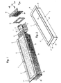
- the recessed luminaire shown in its individual parts in the drawing figures 1 to 19 essentially consists of a cuboid housing 1 with a circumferential, outwardly projecting support frame. 2
- a ballast 10 is arranged in the form of a molded block.
- the ballast 10 ' consists of a printed circuit board 11, on which a plurality of electronic or electrical components 12, 13 and 14 and a terminal block 15 are arranged.
- the ballasts 10 and 10 ' are each secured to a perpendicular from the plane of the mounting plate 6 bent upward support wall 16.
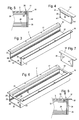
- the housing 1 is formed from an extruded body 1 ', which includes the side walls 20 and 21 with the edge strips 17, 18 and the rear wall 22.
- the ends of this extruded body 1 ' are each provided with end walls 23 and 24, each sealingly with the interposition of sealing plates 25 by means of screws 19 on the planar plane cut end faces 26 and 27 abut the extruded body.
- the two side walls 20 and 21 are each provided with longitudinally extending, equal in height parallel guide grooves 28 and 29, in which the mounting plate 6 can be inserted from an open end side, after this with the bulbs. 7 and the ballast 10 or 10 'and has been equipped with a connector block 30.
- the two side walls 20 and 21 are respectively provided in the vicinity of their upper and front edges with longitudinally extending glass support strips 31 and 32, which are integrally connected thereto, i. integral part of the extruded body 1 'are.
- These glass carrier strips are arranged at the same distance from the rear wall 22 in parallel position to each other.
- the two glass carrier strips 31, 32 in the embodiment of the Fig. 3 at the ends have no physical connection, the two belonging to this extruded body 1 'end walls 23 and 23 are each provided with inwardly directed ribs 35. These ribs 35 are designed such that they bridge a front side between the transmitted light disc 3 and the bolted end wall 23 and 24 existing gap 36, so that this rib 35 serve a gap 36 filling filler 37 as Brown Guinea.
- the transparency plate 3 is in a known manner by means of a strand or bead on the glass support strips 17, 18 applied adhesive 38 (see also Fig. 17 ) attached to this.
- gaps 36 are filled with a resistant filler 37 sealingly on the long sides of the transparency plate 3.
- the extruded body 1' For positive reception of the self-tapping screws 19, with which the end walls 23, 24 are fixed to the extruded body 1 ', the extruded body 1' with four screw 40 (FIG. Fig. 13, 15 . 17 ) Mistake.
- the end walls 23, 24 For these fitting, each have holes 41.
- the longitudinally extending glass support bars 17, 18 on the inner sides of the side walls 20, 21 also present, but at the front ends in each case by transversely extending bar sections 42, 43 connected to each other.
- the glass support bars 17, 18 are made with the strip portions 42, 43 in such a way that the front opening 4 is cut out of an initially closed partition while the glass support strips 17, 18 remain with their connecting bar sections 42, 43.
- the ribs 35 can be omitted on the end walls 23, 24 in this embodiment, because the strip sections 42, 43 are each usable as a filling ground for the filler 36 filling the gap 36.
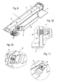
- Fig. 9 to 19 describes how the ballast 10 or 10 'required for the operation of the fluorescent tubes 8, 9 arranged and stored in a manner that good heat dissipation and thus the avoidance of heat accumulation within the housing 1 can be achieved by its heat-generating components.
- the ballast 10 consists of a potted in a metal shell block.
- the metal shell has for its attachment to the front ends protruding tabs 44, 45, which are provided for receiving fastening screws with holes or slots.
- ballast 10 is movably mounted with its tabs 44 and 45. Between the tabs 44 and 45 and the support wall 16, a helical compression spring 52 is arranged on each shaft screw 46, through which the tabs 44, 45 are pressed against the nuts 47.
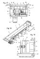
- the arrangement can also be chosen so that the side surface 55 of the ballast 10 rests against the inner surface of the rear wall 22, as in Fig. 15 is shown.
- a mounting plate 6 ' is used, which in addition to the support wall 16 a parallel to the plane of the mounting plate 6' extending wall portion 56 having the bores 50 and 51.
- the circuit board 11 on the shaft bolts 46 means the coil springs 52 are mounted so that the heat generating components, eg. B. 13 and 14 of the ballast 10 ', with their outer surfaces heat-conducting abut spring pressure on the side wall 21 of the housing 1.
- any other spring elements can be used to generate the contact pressure between the ballast 10 and the components of the ballast 10 'and the side wall 21 and the rear wall 22.
- the two shaft screws 46 can be replaced by other guide or bearing elements, for example by rivet bolts.
- Fig. 17 is also the cable connection sleeve 58 visible through which the electrical supply cable is guided.
Landscapes
- Engineering & Computer Science (AREA)
- General Engineering & Computer Science (AREA)
- Power Engineering (AREA)
- Arrangement Of Elements, Cooling, Sealing, Or The Like Of Lighting Devices (AREA)
Abstract
Description
- Die Erfindung betrifft eine Einbauleuchte, bei der ein viereckiges, vorzugsweise als Strangpresskörper ausgebildetes Gehäuse (1) aus Metall mit frontseitiger Öffnung (8) und mit paarweise parallelen Gehäusewänden sowie mit einer daran befestigten Rückwand als Leuchtmittel längliche Leuchtkörper, insbesondere Leuchtstoffröhren, mit den zugehörigen Halteeinrichtungen aufweist und mit einem Vorschaltgerät versehen ist, dessen Bauteile gekapselt in einem Gehäuseblock oder offen einseitig auf einer Leiterplatte angeordnet sind, wobei die frontseitige Öffnung des Gehäuses durch eine innerhalb eines flachen, seitlich nach außen vorspringenden Anlegerahmens angeordnete Durchlichtscheibe aus Glas oder Acrylglas dicht verschlossen ist.
- Aus
DE 202 12 411 U1 ist eine Einbauleuchte der oben genannten Art bekannt, bei der die paarweise parallelen Längswände und die Stirnwände des Gehäuses jeweils aus separaten stranggepressten Wandprofilen bestehen, die durch eine angeschraubte Rückwand miteinander verbunden sind. An den Ecken des Gehäuses sind die Längs- und Stirnwände jeweils auf Gehrung geschnitten, damit sie spaltfrei zusammengefügt werden können. Die Rückwand, auf welcher die Leuchtmittel und das als in einem Metallmantel vergossener Block ausgebildete Vorschaltgerät befestigt sind, besteht aus einem Blechteil, das von außen an die Längs- und Stirnwände angeschraubt ist. Zu diesem Zweck sind die Wandprofile rückseitig mit Schraubkanälen versehen. Dabei ist das Vorschaltgerät mit seiner sich gewöhnlich nur schwach erwärmenden Unterseite meistens unter Zwischenlage einer Dämmplatte auf die Rückwand aufgeschraubt. Eine wirksame Wärmeableitung über die Rückwand findet daher kaum statt. - Innerhalb der Durchlichtscheibe ist im Gehäuse ein Lichtleit- oder Blendschutzgitter angeordnet, das auf Stützrippen der Gehäusewände aufsitzt.
- Bei dieser Einbauleuchte ist das Zuschneiden der Gehäusewände auf Gehrung sehr zeitaufwändig und somit kostenträchtig. Auch das Abdichten der Stoßfugen ist problematisch.
- Die die frontseitige Öffnung des Gehäuses abdeckende Durchlichtscheibe ist mittels eines zusammenhängend umlaufenden Klebstoffbettes auf den Glasträgerleisten befestigt.
- Solche Einbauleuchten werden gewöhnlich in Werkzeugmaschinen eingebaut, die in einer Gehäusewand, in welcher die Einbauleuchte befestigt werden soll, eine entsprechende rechteckige Einbauöffnung aufweisen.
- In Werkzeugmaschinen, die spanabhebende Arbeiten verrichten, kommen die Frontseiten der Einbauleuchten in der Regel mit chemisch aggressiven Kühl- und Schmierstoffen in Berührung. Es ist deshalb unerlässlich, das gesamte Gehäuse hermetisch abzudichten, damit keine aggressiven Gase und/oder Flüssigkeiten in das Gehäuseinnere eindringen können. Weil auch die derzeit zur Verfügung stehenden Klebstoffe, die zur Befestigung der Durchlichtscheibe auf den Glasträgerleisten benutzt werden, nicht ausreichend gegen die aggressiven Kühl- und Schmierstoffe resistent sind, ist es auch erforderlich, das Klebstoffbett, das zwischen der Durchlichtscheibe und den Glasträgerleisten angeordnet ist, davor zu schützen, mit den aggressiven Kühl- und Schmiermitteln bzw. von diesen ausgehenden Gasen in Berührung zu kommen.
- Der Erfindung liegt die Aufgabe zugrunde, eine einfach und kostengünstig herstellbare Einbauleuchte der eingangs genannten Art zu schaffen, bei welcher die Gehäuseteile sowohl bei der Erstmontage als auch bei nachträglichen Reparaturen auf einfache Weise mittels einfacher Dichtungsmittel zu einem allseits zuverlässig wasserdichten Gehäuse zusammengefügt werden können und bei der die Entstehung eines durch elektrische Baugruppen des Vorschaltgerätes verursachte Wärmestaus innerhalb des Gehäuses zumindest weitgehend verhindert werden.
- Gelöst wird diese Aufgabe erfindungsgemäß dadurch, dass das Vorschaltgerät derart federnd beweglich an einem Trägerelement im Gehäuse gelagert ist, dass wenigstens eine Außenseite seines Gehäuseblocks bzw. die sich erwärmenden Bauteile des Vorschaltgerätes mit wenigstens einer Kühlfläche wärmeleitend mit einer Außenwand oder mit der Rückwand des Gehäuses in Kontakt stehen.
- Durch die besondere Anordnung der Leuchtmittel und des Vorschaltgerätes auf einer Montageplatte ist nicht nur deren Einbringung in den Gehäusekörper auf sehr einfache Weise und kostengünstig zu bewerkstelligen, sondern es ist auch möglich, das Vorschaltgerät so mit einer Gehäusewand in wärmeleitenden Kontakt zu bringen, dass keine Wärmestaus entstehen können. Selbstverständlich ist dies nicht nur mit Vorschaltgeräten möglich, die als vergossener Block mit einem Metallmantel zur Verfügung stehen, vielmehr auch mit solchen Vorschaltgeräten, bei denen die elektrischen bzw. elektronischen Bauteile auf einer Leiterplatte quasi freistehend angeordnet sind.
- Anspruch 2 und 3 betreffen die vorteilhafte Ausgestaltung des Trägerelements als Trägerwand und die federnde Lagerung des Vorschaltgerätes im Gehäuse zur Ermöglichung einer einfachen Montage und der Erzeugung einer wärmeleitenden Kontaktierung zwischen einem Gehäuseteil und dem Vorschaltgerät.
- Die Ausgestaltung nach Anspruch 4 ist insofern von Vorteil als Trägerwand und Montageplatte einteilig ausgebildet sind und gemeinsam nur einen Montagevorgang benötigen, also kostensparend ausgebildet sind.
- Auch die Ausgestaltung nach Anspruch 5 dient der Vereinfachung der Montage und Lagerung der Montageplatte.
- Die Ausgestaltung nach Anspruch 6 betrifft eine Ausführungsform, bei der die beiden längs verlaufenden Seitenwände des Gehäuses mit einstückigen und einstückig mit den Seitenwänden verbundenen Glasträgerleisten versehen sind, die keine nachträgliche Bearbeitung erforderlich machen, bei denen es allerdings zweckmäßig ist, die Stirnwände gemäß Anspruch 8 auszugestalten.
- Während es bei der bekannten Einbauleuchte erforderlich ist, die Seitenwände von dem Strangpresskörper jeweils separat mit Gehrung auf Länge zu schneiden und die Rückwand separat herzustellen, kann bei der erfindungsgemäßen Ausführung gemäß Anspruch 6 der gesamte Gehäusekörper, bestehend aus den beiden Seitenwänden und der Rückwand, jeweils in einem Arbeitsgang auf die jeweils benötigte Länge geschnitten werden. Dabei besteht ein weiterer Vorteil darin, dass beim Abschneiden des Gehäusekörpers von dem Strangpresskörper planebene Stirnflächen entstehen, an denen die Stirnwände und das Zwischenlager von Dichtungsmitteln, die aus geeignetem Flachmaterial bestehen können, auf einfache Weise, z. B. durch Schrauben, dicht angebracht werden können.
- Die Ausgestaltung gemäß Anspruch 7 ist insofern von Vorteil, als durch die darin beschriebene Ausbildung der Stirnwände das durch sie vervollständigte Gehäuse mit einem umlaufenden Anlegerahmen versehen wird, der den Einbau der Einbauleuchte in eine dafür vorgesehene Öffnung einer Wand eines Maschinengehäuses oder dgl. begünstigt. Durch die Ausführungsform gemäß Anspruch 10, bei welcher die beiden Gehäusewände an den stirnseitigen Enden durch quer verlaufende Leistungsabschnitte miteinander verbunden sind, wird nicht nur eine höhere Stabilität des Gehäusekörpers erzielt sondern auch die Möglichkeit gegeben, die Durchlichtscheibe auch im Bereich der Stirnwände mittels Klebstoffraupen auf Glasträgerleisten zu befestigen.
- Bei dieser Ausführungsform ist der Strangpresskörper in Höhe der Glasträgerleiste mit einer durchgehenden, parallel zur Rückwand verlaufenden Zwischenwand versehen. Durch Herausschneiden der frontseitigen Öffnung, durch welche das Licht des Leuchtmittels nach außen gelangen kann, werden die von dieser Wand übrig bleibenden Glasträgerleisten gebildet.
- Durch die Ausgestaltung nach Anspruch 11 wird sichergestellt, dass die Durchlichtscheibe dauerhaft auf den Glasträgerleisten befestigt werden kann.
- Anhand der Zeichnung wird die Erfindung im Folgenden näher erläutert. Es zeigt:
- Fig. 1
- in teilweise auseinander gezogener 3D-Ansicht eine Einbauleuchte;
- Fig. 2
- das komplette Gehäuse der Einbauleuchte in 3D- Ansicht;
- Fig. 3
- eine erste Ausführungsform des Strangpresskör- pers, aus dem das Gehäuse gebildet wird, in isometrischer Darstellung;
- Fig. 4
- eine dazu passende Stirnwand in isometrischer Ansicht;
- Fig. 5
- eine Schnittdarstellung des fertigen Gehäuses mit dem Strangpresskörper aus
Fig. 3 im Stirn- wandbereich; - Fig. 6
- eine andere Ausführungsform des Strangpresskör- pers, aus dem das Gehäuse gebildet wird, in isometrischer Ansicht;
- Fig. 7
- eine dazugehörige Stirnwand in isometrischer Ansicht;
- Fig. 8
- eine Schnittdarstellung des fertigen Gehäuses mit dem Strangpresskörper aus
Fig. 6 im Stirn- wandbereich; - Fig. 9
- in 3D-Ansicht eine Montageplatte mit darauf montiertem Leuchtmittel und Vorschaltgerät;
- Fig. 10
- in vergrößertem Ausschnitt die Befestigung des einen Endes des Vorschaltgerätes an der Träger- wand der Montageplatte;
- Fig. 11
- die Befestigung des anderen Endes des Vor- schaltgerätes an der Trägerwand der Montage- platte;
- Fig. 12
- die Befestigungsmittel und deren Anordnung, mit denen das Vorschaltgerät an der Trägerwand be- festigt ist, in vergrößerter Darstellung;
- Fig. 13
- die Stirnansicht des Strangpresskörpers der
Fig. 6 mit eingesetzter Montageplatte und dar- auf montiertem Vorschaltgerät; - Fig. 14
- die Montageplatte der
Fig. 13 als Einzelteil; - Fig. 15
- die Stirnansicht des Strangpresskörpers gemäß
Fig. 3 mit eingesetzter Montageplatte; - Fig. 16
- die Montageplatte der
Fig. 15 als Einzelteil; - Fig. 17
- eine Stirnansicht des fertig montierten Leuch- tengehäuses;
- Fig. 18
- eine Montageplatte gemäß
Fig. 9 mit darauf mon- tiertem Leuchtmittel, jedoch mit einem Vor- schaltgerät, bei dem die elektrischen bzw. e- lektronischen Bauteile offen auf einer Leiter- platte angeordnet sind; - Fig. 19
- in einer geschnittenen Stirnansicht die Monta- geplatte der
Fig. 18 mit an einer Seitenwand anliegenden elektronischen Bauteilen. - Die in den Zeichnungsfiguren 1 bis 19 in ihren Einzelteilen dargestellte Einbauleuchte besteht im Wesentlichen aus einem quaderförmigen Gehäuse 1 mit einem umlaufenden, nach außen vorspringenden Anlegerahmen 2.
- In diesem Gehäuse 1 befindet sich unter einer Durchlichtscheibe 3, die eine frontseitige Öffnung 4 abdeckt, ein Blendschutzgitter 5. Unter bzw. hinter dem Blendschutzgitter 5 befindet sich auf einer Montageplatte 6 das Leuchtmittel 7, das aus zwei parallelen Leuchtstoffröhren 8 und 9 besteht. Parallel neben dem Leuchtmittel 7 ist ein Vorschaltgerät 10 in Form eines vergossenen Blocks angeordnet. Bei der Ausführungsform gemäß
Fig. 18 besteht das Vorschaltgerät 10' aus einer Leiterplatte 11, auf der mehrere elektronische bzw. elektrische Bauteile 12, 13 und 14 sowie ein Anschlussblock 15 angeordnet sind. Dabei sind die Vorschaltgeräte 10 und 10' jeweils an einer rechtwinklig aus der Ebene der Montageplatte 6 nach oben gebogenen Trägerwand 16 befestigt. - Wie nachstehend noch näher erläutert wird, erfolgt diese Befestigung der Vorschaltgeräte 10 bzw. 10' an der Trägerwand 16 auf besondere Weise.
- Das Gehäuse 1 ist gebildet aus einem Strangpresskörper 1', der die Seitenwände 20 und 21 mit den Randleisten 17, 18 sowie die Rückwand 22 umfasst. Die Randleisten 17, 18 bilden die längsseitigen Teile des Anlegerahmens 2 des fertigen Gehäuses 1. Die Enden dieses Strangpresskörpers 1' werden jeweils mit Stirnwänden 23 und 24 versehen, die jeweils unter Zwischenlage von Dichtungsplatten 25 dichtend mittels Schrauben 19 an den planebenen geschnittenen Stirnflächen 26 bzw. 27 der Strangpresskörper anliegen.
- In der Nähe der Rückwand 22 sind die beiden Seitenwände 20 und 21 jeweils mit längs verlaufenden, sich in gleicher Höhe parallel gegenüberliegenden Führungsnuten 28 und 29 versehen, in welche die Montageplatte 6 von einer offenen Stirnseite her eingeschoben werden kann, nachdem diese mit den Leuchtmitteln 7 und dem Vorschaltgerät 10 bzw. 10' sowie mit einem Steckerblock 30 bestückt worden ist.
- Zur Aufnahme der Durchlichtscheibe 3 sind die beiden Seitenwände 20 und 21 in der Nähe ihrer Ober- bzw. Frontkanten jeweils innenseitig mit längs verlaufenden Glasträgerleisten 31 und 32 versehen, die einstückig mit diesen verbunden, d.h. einstückiger Bestandteil des Strangpresskörpers 1' sind. Diese Glasträgerleisten sind in gleichem Abstand von der Rückwand 22 in Parallellage zueinander angeordnet.
- Wie aus den
Fig. 13, 15 und17 ersichtlich ist, befinden sich unterhalb dieser Glasträgerleisten 31 und 32 in einem der Höhe des Blendschutzgitters 5 entsprechenden, vertikalen Abstand, zusätzliche längs verlaufende Stützrippen 33 und 34, auf denen das Blendschutzgitter 5 lose gelagert ist. - Da die beiden Glasträgerleisten 31, 32 bei der Ausführungsform der
Fig. 3 an den Enden keine körperliche Verbindung haben, sind die beiden zu diesem Strangpresskörper 1' gehörenden Stirnwände 23 und 23 jeweils mit nach innen gerichteten Rippen 35 versehen. Diese Rippen 35 sind so ausgebildet, dass sie einen stirnseitig zwischen der Durchlichtscheibe 3 und der angeschraubten Stirnwand 23 bzw. 24 bestehenden Spalt 36 überbrücken, so dass diese Rippe 35 einem den Spalt 36 ausfüllenden Füllstoff 37 als Füllboden dienen. - Die Durchlichtscheibe 3 ist in bekannter Art mittels eines als Strang oder Raupe auf die Glasträgerleisten 17, 18 aufgetragenen Klebers 38 (siehe auch
Fig. 17 ) auf diesen befestigt. Zu dessen Schutz gegen aggressive Gase und/oder Flüssigkeiten, die auf die Frontseite einer eingebauten Einbauleuchte auftreffen können, sind auch an den Längsseiten der Durchlichtscheibe 3 solche Spalte 36 mit einem resistenten Füllstoff 37 dichtend ausgefüllt. - Zur formschlüssigen Aufnahme der selbstschneidenden Schrauben 19, mit denen die Stirnwände 23, 24 am Strangpresskörper 1' befestigt werden, ist der Strangpresskörper 1' mit vier Schraubkanälen 40 (
Fig. 13, 15 ,17 ) versehen. Zu diesen passend weisen die Stirnwände 23, 24 jeweils Bohrungen 41 auf. - Zur Vervollständigung des umlaufenden Anlegerahmens 2 sind die auf Kosten sparende Weise im Rohzustand als Strangpressprofile hergestellten und auf passende Form geschnittenen Stirnwände 23, 24 ebenfalls mit Randleisten 17', 18' versehen.
- Bei der Ausführungsform der
Fig. 6 sind die längs verlaufenden Glasträgerleisten 17, 18 an den Innenseiten der Seitenwände 20, 21 ebenfalls vorhanden, jedoch an den stirnseitigen Enden jeweils durch quer verlaufende Leistenabschnitte 42, 43 miteinander verbunden. Bei dieser Ausführungsform werden die Glasträgerleisten 17, 18 mit den Leistenabschnitten 42, 43 in der Weise hergestellt, dass aus einer zunächst geschlossenen Zwischenwand die frontseitige Öffnung 4 herausgeschnitten wird und dabei die Glasträgerleisten 17, 18 mit den sie verbindenden Leistenabschnitten 42, 43 stehen bleiben. - Aufgrund des Vorhandenseins der Leistenabschnitte 42, 43 können bei dieser Ausführung die Rippen 35 an den Stirnwänden 23, 24 entfallen, weil die Leistenabschnitte 42, 43 jeweils als Füllboden für den die Spalte 36 ausfüllenden Füllstoff 37 benutzbar sind.
- Wie aus
Fig. 8 erkennbar ist, stehen dabei die Stirnflächen der Leistenabschnitte 42, 43 auch als Anlage für die Dichtungsplatten 25 zur Verfügung, so dass der Innenraum des Gehäuses 1 stirnseitig vollständig abgedichtet werden kann. - Im Folgenden wird nun anhand der
Fig. 9 bis 19 beschrieben, wie das für den Betrieb der Leuchtstoffröhren 8, 9 benötigte Vorschaltgerät 10 bzw. 10' auf eine Art angeordnet und gelagert ist, dass von seinen Wärme erzeugenden Bauteilen eine gute Wärmeableitung und somit die Vermeidung von Wärmestaus innerhalb des Gehäuses 1 erreicht werden kann. - Bei der in den
Fig. 9 bis 17 dargestellten Ausführungsform besteht das Vorschaltgerät 10 aus einem in einem Metallmantel vergossenem Block. Der Metallmantel weist zu seiner Befestigung an den stirnseitigen Enden vorstehende Laschen 44, 45 auf, die zur Aufnahme von Befestigungsschrauben mit Bohrungen oder Schlitzen versehen sind. - Hier sind zur Befestigung des Vorschaltgerätes 10 an der zwischen zwei flachen Endabschnitten 48, 49 der Montageplatte 6 rechtwinklig hochstehenden Trägerwand 16 in zwei Bohrungen 50 und 51 jeweils in Parallellage zur Rückwand 22 und zur Montageplatte 6 Schaftschrauben 46 mit Muttern 47 angeordnet. Auf diesen Schaftschrauben 46 ist das Vorschaltgerät 10 mit seinen Laschen 44 und 45 beweglich gelagert. Zwischen den Laschen 44 und 45 und der Trägerwand 16 ist auf jeder Schaftschraube 46 eine Schraubendruckfeder 52 angeordnet, durch welche die Laschen 44, 45 gegen die Muttern 47 gedrückt werden. Durch entsprechende Wahl des Abstandes a der Trägerwand 16 von der gegenüberliegenden Seitenwand 21 und des Abstandes a1 der Muttern 47 von der Trägerwand 16 wird erreicht, dass die Seitenfläche 55 des Vorschaltgerätes federnd an der Innenseite der Seitenwand 21 wärmeleitend anliegt.
- In analoger Weise kann die Anordnung auch so gewählt werden, dass die Seitenfläche 55 des Vorschaltgerätes 10 an der Innenfläche der Rückwand 22 anliegt, wie das in
Fig. 15 dargestellt ist. Dabei wird eine Montageplatte 6' verwendet, die an der Trägerwand 16 zusätzlich einen parallel zur Ebene der Montageplatte 6' verlaufenden Wandabschnitt 56 mit den Bohrungen 50 und 51 aufweist. Mittels der Schaftschrauben 46 und der Muttern 47 sowie mittels der Schraubendruckfedern 52, ist dabei das Vorschaltgerät 10 nach unten, d.h. gegen die Rückwand 22, federnd an diesem Wandabschnitt 56 gelagert. - Wie aus den
Fig. 18 und 19 erkennbar ist, kann die Lagerung der Leiterplatte 11 des offenen Vorschaltgerätes 10' prinzipiell auf die gleiche Weise erfolgen, wie die des Vorschaltgerätes 10 an der Trägerwand 16. Auch hier ist die Leiterplatte 11 auf den Schaftschrauben 46 mittels der Schraubenfedern 52 so gelagert, dass die Wärme erzeugenden Bauteile, z. B. 13 und 14 des Vorschaltgerätes 10', mit ihren Außenflächen wärmeleitend unter Federdruck an der Seitenwand 21 des Gehäuses 1 anliegen. - Es ist darauf hinzuweisen, dass anstelle der Schraubendruckfedern 52 beliebige andere Federelemente verwendet werden können, um den Kontaktdruck zwischen dem Vorschaltgerät 10 bzw. den Bauteilen des Vorschaltgerätes 10' und der Seitenwand 21 bzw. der Rückwand 22 zu erzeugen.
- Auch die beiden Schaftschrauben 46 können durch andere Führungs- oder Lagerelemente, beispielsweise durch Nietbolzen, ersetzt werden.
- In
Fig. 17 ist auch die Kabelanschlussmuffe 58 sichtbar, durch welche das elektrische Versorgungskabel geführt ist.
Claims (11)
- Einbauleuchte, bei der ein viereckiges, vorzugsweise als Strangpresskörper ausgebildetes Gehäuse (1) aus Metall mit frontseitiger Öffnung (8) und mit paarweise parallelen Gehäusewänden (2 bis 5) sowie mit einer daran befestigten Rückwand (6) als Leuchtmittel längliche Leuchtkörper, insbesondere Leuchtoffröhren, mit den zugehörigen Halteeinrichtungen (12) aufweist und mit einem Vorschaltgerät (10) versehen ist, dessen Bauteile gekapselt in einem Gehäuseblock (13) oder offen einseitig auf einer Leiterplatte (11) angeordnet sind, wobei die frontseitige Öffnung (8) des Gehäuses (1) durch eine innerhalb eines flachen, seitlich nach außen vorspringenden Anlegerahmens (25) angeordnete Durchlichtscheibe (9) aus Glas oder Acrylglas dicht verschlossen ist,
dadurch gekennzeichnet,
dass das Vorschaltgerät (10, 10') derart federnd beweglich an einem Trägerelement (16, 56) im Gehäuse (1) gelagert ist, dass wenigstens eine Außenseite (55) seines Gehäuseblocks bzw. die sich erwärmenden Bauteile des Vorschaltgerätes (10, 10') mit wenigstens einer Kühlfläche wärmeleitend mit einer Außenwand (21) oder mit der Rückwand (6) des Gehäuses (1) in Kontakt stehen. - Einbauleuchte nach Anspruch 1, dadurch gekennzeichnet, dass das Trägerelement (16, 56) aus einem parallel zu einer Gehäusewand (20, 21) bzw. zur Rückwand (6) des Gehäuses (1) verlaufenden Trägerwand (16) besteht und wenigstens eine Führung (46) aufweist, auf der das Vorschaltgerät (10, 10') federnd verschiebbar gelagert ist, wobei zwischen der Trägerwand (16) und dem Vorschaltgerät (10, 10') bzw. der Leiterplatte (11) wenigstens eine Druckfeder (52) angeordnet ist.
- Einbauleuchte nach Anspruch 2, dadurch gekennzeichnet, dass als Führungen an der Trägerwand (16) wenigstens zwei Schaftschrauben (46) angeordnet sind, welche jeweils eine Führungsbohrung oder einen Führungsschlitz des Vorschaltgerätes (10, 10'), d.h. des Gehäuseblocks bzw. der Leiterplatte (11) durchragen und welche jeweils mit einer Drückfeder (52) versehen sind.
- Einbauleuchte nach Anspruch 2 oder 3, dadurch gekennzeichnet, dass die Trägerwand (16) Teil einer Montageplatte (6, 6') oder an einer solchen befestigt ist, auf welcher das Leuchtmittel (7) und das Vorschaltgerät (10, 10') montiert sind.
- Einbauleuchte nach Anspruch 4, dadurch gekennzeichnet, dass die beiden längsseitigen Gehäusewände (2, 3) innenseitig jeweils mit Führungsnuten (28, 29) versehen ist, in welche die Montageplatte (6) von einer offenen Gehäusestirnseite her einschiebbar ist.
- Einbauleuchte nach Anspruch 1, dadurch gekennzeichnet, dass die längsseitigen Gehäusewände (2 und 3), die mit der Rückwand (6) einen einstückigen metallenen Strangpressprofilkörper (20) bilden, an den Innenseiten in frontseitiger Randnähe der Gehäusewände (2, 3) jeweils eine zumindest annähernd rechtwinklig vorspringenden Glasträgerleiste (31, 32) für die Durchlichtscheibe (9) und am selben Rand außenseitig eine rechtwinklig abstehende, den flachen Anlegerahmen (2) bildende Randleiste (26) aufweisen.
- Einbauleuchte nach einem der Ansprüche 1 bis 6, dadurch gekennzeichnet, dass das Gehäuse (1) an seinen beiden Stirnseiten jeweils mit dicht schließenden Stirnwänden (23, 24) versehen ist, die aus einem im Wesentlichen L- förmigen Strangpressprofil gebildet sind, das entlang einer Randkante eine Randleiste (18') aufweist, welche den stirnseitigen Teil des Anlegerahmens (2) bildet.
- Einbauleuchte nach Anspruch 7, dadurch gekennzeichnet, dass die stirnseitigen Enden der Glasträgerleisten (31, 32) jeweils durch quer verlaufende Leistenabschnitte (42, 43) miteinander verbunden sind.
- Einbauleuchte nach Anspruch 1, dadurch gekennzeichnet, dass die Durchlichtscheibe (3) bündig in der Ebene des umlaufenden Anlegerahmens (2) liegend auf wenigstens zwei Glasträgerleisten (31, 32) der beiden Seitenwände (20, 21) mittels zweier Klebstoffraupen (38) befestigt ist.
- Einbauleuchte nach Anspruch 9, dadurch gekennzeichnet, dass zwischen der Durchlichtscheibe (3) und den in ihrer Ebene liegenden Rändern der Seitenwände (20, 21) ein umlaufender Spalt (36) besteht, der mittels eines elastischen, die Klebstoffraupen (38) gegen schädliche äußere Einflüsse, insbesondere gegen chemisch aggresive Gase und Flüssigkeiten, schützenden Füllstoffs (37) dichtend ausgefüllt ist.
- Einbauleuchte nach Anspruch 10, dadurch gekennzeichnet, dass die Stirnwände (23, 24) im Bereich der Glasträgerleisten (31, 32) jeweils mit einer Rippe (35) versehen sind, die den Spalt (36) innerhalb der Durchlichtscheibe (3) überbrückt.
Priority Applications (1)
| Application Number | Priority Date | Filing Date | Title |
|---|---|---|---|
| PL09006145T PL2123976T3 (pl) | 2008-05-17 | 2009-05-06 | Oprawa oświetleniowa do zabudowy |
Applications Claiming Priority (1)
| Application Number | Priority Date | Filing Date | Title |
|---|---|---|---|
| DE202008006765U DE202008006765U1 (de) | 2008-05-17 | 2008-05-17 | Einbauleuchte |
Publications (2)
| Publication Number | Publication Date |
|---|---|
| EP2123976A1 true EP2123976A1 (de) | 2009-11-25 |
| EP2123976B1 EP2123976B1 (de) | 2012-07-11 |
Family
ID=39670617
Family Applications (1)
| Application Number | Title | Priority Date | Filing Date |
|---|---|---|---|
| EP09006145A Not-in-force EP2123976B1 (de) | 2008-05-17 | 2009-05-06 | Einbauleuchte |
Country Status (4)
| Country | Link |
|---|---|
| EP (1) | EP2123976B1 (de) |
| DE (1) | DE202008006765U1 (de) |
| ES (1) | ES2389676T3 (de) |
| PL (1) | PL2123976T3 (de) |
Cited By (4)
| Publication number | Priority date | Publication date | Assignee | Title |
|---|---|---|---|---|
| AT12995U1 (de) * | 2011-10-10 | 2013-03-15 | Zumtobel Lighting Gmbh | Kühlvorrichtung für betriebsgeräte von leuchten sowie leuchte |
| CN103047633A (zh) * | 2011-10-11 | 2013-04-17 | 台达电子工业股份有限公司 | 防水装置 |
| WO2014075825A1 (de) * | 2012-11-16 | 2014-05-22 | Osram Gmbh | Leuchtenkörper und verfahren zum herstellen eines leuchtenkörpers |
| CN115419848A (zh) * | 2022-11-03 | 2022-12-02 | 和谐光电科技(泉州)有限公司 | 一种led灯具 |
Families Citing this family (4)
| Publication number | Priority date | Publication date | Assignee | Title |
|---|---|---|---|---|
| DE202008007211U1 (de) * | 2008-05-29 | 2009-10-08 | Ledon Lighting Gmbh | Leuchtengehäuse, insbesondere für eine LED-Leuchte, mit Dichtungselement |
| DE102012108798A1 (de) * | 2012-09-18 | 2014-05-15 | Elb-Schliff Werkzeugmaschinen Gmbh | Beleuchtungseinrichtung für Werkzeugmaschine |
| DE202015103702U1 (de) * | 2015-07-15 | 2016-10-19 | Zumtobel Lighting Gmbh | Leuchtengehäuse |
| EP4700281A1 (de) * | 2024-08-20 | 2026-02-25 | Thorn Lighting Limited | Leuchte und verfahren zur herstellung einer leuchte |
Citations (4)
| Publication number | Priority date | Publication date | Assignee | Title |
|---|---|---|---|---|
| US5136493A (en) | 1991-11-25 | 1992-08-04 | U.S. Pole Company, Inc. | Heat dissipating outdoor lamp holder |
| DE20212411U1 (de) | 2002-08-13 | 2002-11-21 | FKB GmbH, 78727 Oberndorf | Einbauleuchte |
| US20070030682A1 (en) | 2005-08-03 | 2007-02-08 | Ruud Lighting, Inc. | Industrial light fixture with spring-spacer apparatus |
| US20080285266A1 (en) * | 2007-05-14 | 2008-11-20 | Edward John Thomas | Thermal management for fluorescent ballast and fixture system |
-
2008
- 2008-05-17 DE DE202008006765U patent/DE202008006765U1/de not_active Expired - Lifetime
-
2009
- 2009-05-06 EP EP09006145A patent/EP2123976B1/de not_active Not-in-force
- 2009-05-06 PL PL09006145T patent/PL2123976T3/pl unknown
- 2009-05-06 ES ES09006145T patent/ES2389676T3/es active Active
Patent Citations (4)
| Publication number | Priority date | Publication date | Assignee | Title |
|---|---|---|---|---|
| US5136493A (en) | 1991-11-25 | 1992-08-04 | U.S. Pole Company, Inc. | Heat dissipating outdoor lamp holder |
| DE20212411U1 (de) | 2002-08-13 | 2002-11-21 | FKB GmbH, 78727 Oberndorf | Einbauleuchte |
| US20070030682A1 (en) | 2005-08-03 | 2007-02-08 | Ruud Lighting, Inc. | Industrial light fixture with spring-spacer apparatus |
| US20080285266A1 (en) * | 2007-05-14 | 2008-11-20 | Edward John Thomas | Thermal management for fluorescent ballast and fixture system |
Cited By (5)
| Publication number | Priority date | Publication date | Assignee | Title |
|---|---|---|---|---|
| AT12995U1 (de) * | 2011-10-10 | 2013-03-15 | Zumtobel Lighting Gmbh | Kühlvorrichtung für betriebsgeräte von leuchten sowie leuchte |
| CN103047633A (zh) * | 2011-10-11 | 2013-04-17 | 台达电子工业股份有限公司 | 防水装置 |
| WO2014075825A1 (de) * | 2012-11-16 | 2014-05-22 | Osram Gmbh | Leuchtenkörper und verfahren zum herstellen eines leuchtenkörpers |
| CN115419848A (zh) * | 2022-11-03 | 2022-12-02 | 和谐光电科技(泉州)有限公司 | 一种led灯具 |
| CN115419848B (zh) * | 2022-11-03 | 2023-02-10 | 和谐光电科技(泉州)有限公司 | 一种led灯具 |
Also Published As
| Publication number | Publication date |
|---|---|
| PL2123976T3 (pl) | 2012-11-30 |
| ES2389676T3 (es) | 2012-10-30 |
| EP2123976B1 (de) | 2012-07-11 |
| DE202008006765U1 (de) | 2008-07-31 |
Similar Documents
| Publication | Publication Date | Title |
|---|---|---|
| EP2123976B1 (de) | Einbauleuchte | |
| EP2247892B1 (de) | Leuchte | |
| DE102012103912B4 (de) | Kühl- oder Gefrierschrank | |
| DE202010012629U1 (de) | Lichtleiste für Möbel, insbesondere Vitrinen | |
| DE102014112657A1 (de) | Leuchte für ein Lichtbandsystem | |
| DE20311557U1 (de) | Leuchte für Beleuchtungszwecke | |
| DE102016105020A1 (de) | Langfeldleuchte bestehend aus einem, zwei oder mehreren Metallprofilkörpermodulen, dazu angepassten LED-Modulen und Verbindungselementen | |
| EP2642193B1 (de) | LED-Feuchtraumleuchte | |
| EP2375149B1 (de) | Lichtbandsystem mit nachrüstbarer Optik | |
| EP2913582A1 (de) | Diffusor für eine Leuchte | |
| DE202010012968U1 (de) | An einem Möbelteil befestigte Lichtleiste | |
| DE202014100998U1 (de) | LED-Leuchte und LED-Leuchten-Batterie | |
| EP2924337B1 (de) | Leuchte mit einem lichtleiter zur erzeugung von entblendetem, teilflächigen licht | |
| DE102006001981A1 (de) | Lichtleiste | |
| EP3993197A1 (de) | Längliches leuchtentragschienensystem, kit zum zusammenbau desselben und längliches abdeckelement dafür | |
| DE102012102652B4 (de) | Beleuchtungsanordnung mit Leuchtdioden | |
| EP1389711B1 (de) | Einbauleuchte | |
| CH694820A5 (de) | Modulares Lichtsystem. | |
| EP2910843B1 (de) | Beleuchtungseinheit | |
| AT12379U1 (de) | Einbauleuchte | |
| DE202013005228U1 (de) | Fachboden für Möbel, insbesondere für einen Küchenhängeschrank sowie Küchenhängeschrank | |
| DE202009006777U1 (de) | Wannenreflektor | |
| EP2982904B1 (de) | Leuchte | |
| EP2910846B1 (de) | Beleuchtungseinheit und Trägerkörper für die Beleuchtungseinheit | |
| DE202014002724U1 (de) | Leuchte |
Legal Events
| Date | Code | Title | Description |
|---|---|---|---|
| PUAI | Public reference made under article 153(3) epc to a published international application that has entered the european phase |
Free format text: ORIGINAL CODE: 0009012 |
|
| AK | Designated contracting states |
Kind code of ref document: A1 Designated state(s): AT BE BG CH CY CZ DE DK EE ES FI FR GB GR HR HU IE IS IT LI LT LU LV MC MK MT NL NO PL PT RO SE SI SK TR |
|
| 17P | Request for examination filed |
Effective date: 20091223 |
|
| 17Q | First examination report despatched |
Effective date: 20101207 |
|
| REG | Reference to a national code |
Ref country code: DE Ref legal event code: R079 Ref document number: 502009004048 Country of ref document: DE Free format text: PREVIOUS MAIN CLASS: F21V0023020000 Ipc: F21V0031000000 |
|
| RIC1 | Information provided on ipc code assigned before grant |
Ipc: F21V 31/00 20060101AFI20111223BHEP |
|
| GRAP | Despatch of communication of intention to grant a patent |
Free format text: ORIGINAL CODE: EPIDOSNIGR1 |
|
| GRAS | Grant fee paid |
Free format text: ORIGINAL CODE: EPIDOSNIGR3 |
|
| GRAA | (expected) grant |
Free format text: ORIGINAL CODE: 0009210 |
|
| AK | Designated contracting states |
Kind code of ref document: B1 Designated state(s): AT BE BG CH CY CZ DE DK EE ES FI FR GB GR HR HU IE IS IT LI LT LU LV MC MK MT NL NO PL PT RO SE SI SK TR |
|
| REG | Reference to a national code |
Ref country code: GB Ref legal event code: FG4D Free format text: NOT ENGLISH |
|
| REG | Reference to a national code |
Ref country code: CH Ref legal event code: EP |
|
| REG | Reference to a national code |
Ref country code: AT Ref legal event code: REF Ref document number: 566335 Country of ref document: AT Kind code of ref document: T Effective date: 20120715 |
|
| REG | Reference to a national code |
Ref country code: CH Ref legal event code: NV Representative=s name: BRAUNPAT BRAUN EDER AG Ref country code: IE Ref legal event code: FG4D Free format text: LANGUAGE OF EP DOCUMENT: GERMAN |
|
| REG | Reference to a national code |
Ref country code: DE Ref legal event code: R096 Ref document number: 502009004048 Country of ref document: DE Effective date: 20120830 |
|
| REG | Reference to a national code |
Ref country code: ES Ref legal event code: FG2A Ref document number: 2389676 Country of ref document: ES Kind code of ref document: T3 Effective date: 20121030 |
|
| REG | Reference to a national code |
Ref country code: NL Ref legal event code: VDEP Effective date: 20120711 |
|
| REG | Reference to a national code |
Ref country code: PL Ref legal event code: T3 |
|
| REG | Reference to a national code |
Ref country code: LT Ref legal event code: MG4D Effective date: 20120711 |
|
| PG25 | Lapsed in a contracting state [announced via postgrant information from national office to epo] |
Ref country code: NO Free format text: LAPSE BECAUSE OF FAILURE TO SUBMIT A TRANSLATION OF THE DESCRIPTION OR TO PAY THE FEE WITHIN THE PRESCRIBED TIME-LIMIT Effective date: 20121011 Ref country code: IS Free format text: LAPSE BECAUSE OF FAILURE TO SUBMIT A TRANSLATION OF THE DESCRIPTION OR TO PAY THE FEE WITHIN THE PRESCRIBED TIME-LIMIT Effective date: 20121111 Ref country code: FI Free format text: LAPSE BECAUSE OF FAILURE TO SUBMIT A TRANSLATION OF THE DESCRIPTION OR TO PAY THE FEE WITHIN THE PRESCRIBED TIME-LIMIT Effective date: 20120711 Ref country code: HR Free format text: LAPSE BECAUSE OF FAILURE TO SUBMIT A TRANSLATION OF THE DESCRIPTION OR TO PAY THE FEE WITHIN THE PRESCRIBED TIME-LIMIT Effective date: 20120711 Ref country code: CY Free format text: LAPSE BECAUSE OF FAILURE TO SUBMIT A TRANSLATION OF THE DESCRIPTION OR TO PAY THE FEE WITHIN THE PRESCRIBED TIME-LIMIT Effective date: 20120711 Ref country code: LT Free format text: LAPSE BECAUSE OF FAILURE TO SUBMIT A TRANSLATION OF THE DESCRIPTION OR TO PAY THE FEE WITHIN THE PRESCRIBED TIME-LIMIT Effective date: 20120711 |
|
| PG25 | Lapsed in a contracting state [announced via postgrant information from national office to epo] |
Ref country code: SE Free format text: LAPSE BECAUSE OF FAILURE TO SUBMIT A TRANSLATION OF THE DESCRIPTION OR TO PAY THE FEE WITHIN THE PRESCRIBED TIME-LIMIT Effective date: 20120711 Ref country code: SI Free format text: LAPSE BECAUSE OF FAILURE TO SUBMIT A TRANSLATION OF THE DESCRIPTION OR TO PAY THE FEE WITHIN THE PRESCRIBED TIME-LIMIT Effective date: 20120711 Ref country code: PT Free format text: LAPSE BECAUSE OF FAILURE TO SUBMIT A TRANSLATION OF THE DESCRIPTION OR TO PAY THE FEE WITHIN THE PRESCRIBED TIME-LIMIT Effective date: 20121112 Ref country code: GR Free format text: LAPSE BECAUSE OF FAILURE TO SUBMIT A TRANSLATION OF THE DESCRIPTION OR TO PAY THE FEE WITHIN THE PRESCRIBED TIME-LIMIT Effective date: 20121012 Ref country code: LV Free format text: LAPSE BECAUSE OF FAILURE TO SUBMIT A TRANSLATION OF THE DESCRIPTION OR TO PAY THE FEE WITHIN THE PRESCRIBED TIME-LIMIT Effective date: 20120711 |
|
| PG25 | Lapsed in a contracting state [announced via postgrant information from national office to epo] |
Ref country code: NL Free format text: LAPSE BECAUSE OF FAILURE TO SUBMIT A TRANSLATION OF THE DESCRIPTION OR TO PAY THE FEE WITHIN THE PRESCRIBED TIME-LIMIT Effective date: 20120711 |
|
| PG25 | Lapsed in a contracting state [announced via postgrant information from national office to epo] |
Ref country code: EE Free format text: LAPSE BECAUSE OF FAILURE TO SUBMIT A TRANSLATION OF THE DESCRIPTION OR TO PAY THE FEE WITHIN THE PRESCRIBED TIME-LIMIT Effective date: 20120711 Ref country code: DK Free format text: LAPSE BECAUSE OF FAILURE TO SUBMIT A TRANSLATION OF THE DESCRIPTION OR TO PAY THE FEE WITHIN THE PRESCRIBED TIME-LIMIT Effective date: 20120711 Ref country code: RO Free format text: LAPSE BECAUSE OF FAILURE TO SUBMIT A TRANSLATION OF THE DESCRIPTION OR TO PAY THE FEE WITHIN THE PRESCRIBED TIME-LIMIT Effective date: 20120711 Ref country code: CZ Free format text: LAPSE BECAUSE OF FAILURE TO SUBMIT A TRANSLATION OF THE DESCRIPTION OR TO PAY THE FEE WITHIN THE PRESCRIBED TIME-LIMIT Effective date: 20120711 |
|
| PLBE | No opposition filed within time limit |
Free format text: ORIGINAL CODE: 0009261 |
|
| STAA | Information on the status of an ep patent application or granted ep patent |
Free format text: STATUS: NO OPPOSITION FILED WITHIN TIME LIMIT |
|
| PG25 | Lapsed in a contracting state [announced via postgrant information from national office to epo] |
Ref country code: SK Free format text: LAPSE BECAUSE OF FAILURE TO SUBMIT A TRANSLATION OF THE DESCRIPTION OR TO PAY THE FEE WITHIN THE PRESCRIBED TIME-LIMIT Effective date: 20120711 |
|
| 26N | No opposition filed |
Effective date: 20130412 |
|
| PG25 | Lapsed in a contracting state [announced via postgrant information from national office to epo] |
Ref country code: BG Free format text: LAPSE BECAUSE OF FAILURE TO SUBMIT A TRANSLATION OF THE DESCRIPTION OR TO PAY THE FEE WITHIN THE PRESCRIBED TIME-LIMIT Effective date: 20121011 |
|
| PGFP | Annual fee paid to national office [announced via postgrant information from national office to epo] |
Ref country code: GB Payment date: 20130528 Year of fee payment: 5 |
|
| REG | Reference to a national code |
Ref country code: DE Ref legal event code: R097 Ref document number: 502009004048 Country of ref document: DE Effective date: 20130412 |
|
| PGFP | Annual fee paid to national office [announced via postgrant information from national office to epo] |
Ref country code: IT Payment date: 20130424 Year of fee payment: 5 Ref country code: PL Payment date: 20130416 Year of fee payment: 5 Ref country code: FR Payment date: 20130502 Year of fee payment: 5 |
|
| BERE | Be: lapsed |
Owner name: FKB G.M.B.H. Effective date: 20130531 |
|
| PG25 | Lapsed in a contracting state [announced via postgrant information from national office to epo] |
Ref country code: MC Free format text: LAPSE BECAUSE OF FAILURE TO SUBMIT A TRANSLATION OF THE DESCRIPTION OR TO PAY THE FEE WITHIN THE PRESCRIBED TIME-LIMIT Effective date: 20120711 |
|
| REG | Reference to a national code |
Ref country code: IE Ref legal event code: MM4A |
|
| PG25 | Lapsed in a contracting state [announced via postgrant information from national office to epo] |
Ref country code: BE Free format text: LAPSE BECAUSE OF NON-PAYMENT OF DUE FEES Effective date: 20130531 |
|
| PG25 | Lapsed in a contracting state [announced via postgrant information from national office to epo] |
Ref country code: IE Free format text: LAPSE BECAUSE OF NON-PAYMENT OF DUE FEES Effective date: 20130506 |
|
| GBPC | Gb: european patent ceased through non-payment of renewal fee |
Effective date: 20140506 |
|
| PG25 | Lapsed in a contracting state [announced via postgrant information from national office to epo] |
Ref country code: MT Free format text: LAPSE BECAUSE OF FAILURE TO SUBMIT A TRANSLATION OF THE DESCRIPTION OR TO PAY THE FEE WITHIN THE PRESCRIBED TIME-LIMIT Effective date: 20120711 |
|
| REG | Reference to a national code |
Ref country code: FR Ref legal event code: ST Effective date: 20150130 |
|
| PG25 | Lapsed in a contracting state [announced via postgrant information from national office to epo] |
Ref country code: IT Free format text: LAPSE BECAUSE OF NON-PAYMENT OF DUE FEES Effective date: 20140506 |
|
| PG25 | Lapsed in a contracting state [announced via postgrant information from national office to epo] |
Ref country code: FR Free format text: LAPSE BECAUSE OF NON-PAYMENT OF DUE FEES Effective date: 20140602 Ref country code: GB Free format text: LAPSE BECAUSE OF NON-PAYMENT OF DUE FEES Effective date: 20140506 |
|
| PG25 | Lapsed in a contracting state [announced via postgrant information from national office to epo] |
Ref country code: TR Free format text: LAPSE BECAUSE OF FAILURE TO SUBMIT A TRANSLATION OF THE DESCRIPTION OR TO PAY THE FEE WITHIN THE PRESCRIBED TIME-LIMIT Effective date: 20120711 |
|
| PG25 | Lapsed in a contracting state [announced via postgrant information from national office to epo] |
Ref country code: LU Free format text: LAPSE BECAUSE OF NON-PAYMENT OF DUE FEES Effective date: 20130506 Ref country code: MK Free format text: LAPSE BECAUSE OF FAILURE TO SUBMIT A TRANSLATION OF THE DESCRIPTION OR TO PAY THE FEE WITHIN THE PRESCRIBED TIME-LIMIT Effective date: 20120711 Ref country code: HU Free format text: LAPSE BECAUSE OF FAILURE TO SUBMIT A TRANSLATION OF THE DESCRIPTION OR TO PAY THE FEE WITHIN THE PRESCRIBED TIME-LIMIT; INVALID AB INITIO Effective date: 20090506 |
|
| PG25 | Lapsed in a contracting state [announced via postgrant information from national office to epo] |
Ref country code: PL Free format text: LAPSE BECAUSE OF NON-PAYMENT OF DUE FEES Effective date: 20140506 |
|
| REG | Reference to a national code |
Ref country code: PL Ref legal event code: LAPE |
|
| PGFP | Annual fee paid to national office [announced via postgrant information from national office to epo] |
Ref country code: AT Payment date: 20160421 Year of fee payment: 8 |
|
| PGFP | Annual fee paid to national office [announced via postgrant information from national office to epo] |
Ref country code: ES Payment date: 20170601 Year of fee payment: 9 |
|
| REG | Reference to a national code |
Ref country code: AT Ref legal event code: MM01 Ref document number: 566335 Country of ref document: AT Kind code of ref document: T Effective date: 20170506 |
|
| PG25 | Lapsed in a contracting state [announced via postgrant information from national office to epo] |
Ref country code: AT Free format text: LAPSE BECAUSE OF NON-PAYMENT OF DUE FEES Effective date: 20170506 |
|
| REG | Reference to a national code |
Ref country code: CH Ref legal event code: PCAR Free format text: NEW ADDRESS: HOLEESTRASSE 87, 4054 BASEL (CH) |
|
| PGFP | Annual fee paid to national office [announced via postgrant information from national office to epo] |
Ref country code: DE Payment date: 20180411 Year of fee payment: 10 Ref country code: CH Payment date: 20180530 Year of fee payment: 10 |
|
| REG | Reference to a national code |
Ref country code: DE Ref legal event code: R082 Ref document number: 502009004048 Country of ref document: DE Representative=s name: PATENTANWAELTE RUFF, WILHELM, BEIER, DAUSTER &, DE Ref country code: DE Ref legal event code: R082 Ref document number: 502009004048 Country of ref document: DE |
|
| REG | Reference to a national code |
Ref country code: ES Ref legal event code: FD2A Effective date: 20190913 |
|
| PG25 | Lapsed in a contracting state [announced via postgrant information from national office to epo] |
Ref country code: ES Free format text: LAPSE BECAUSE OF NON-PAYMENT OF DUE FEES Effective date: 20180507 |
|
| REG | Reference to a national code |
Ref country code: DE Ref legal event code: R119 Ref document number: 502009004048 Country of ref document: DE |
|
| REG | Reference to a national code |
Ref country code: CH Ref legal event code: PL |
|
| PG25 | Lapsed in a contracting state [announced via postgrant information from national office to epo] |
Ref country code: LI Free format text: LAPSE BECAUSE OF NON-PAYMENT OF DUE FEES Effective date: 20190531 Ref country code: CH Free format text: LAPSE BECAUSE OF NON-PAYMENT OF DUE FEES Effective date: 20190531 |
|
| PG25 | Lapsed in a contracting state [announced via postgrant information from national office to epo] |
Ref country code: DE Free format text: LAPSE BECAUSE OF NON-PAYMENT OF DUE FEES Effective date: 20191203 |