EP2124013A2 - Pulvérisateur de gaz lacrimogène - Google Patents
Pulvérisateur de gaz lacrimogène Download PDFInfo
- Publication number
- EP2124013A2 EP2124013A2 EP09005450A EP09005450A EP2124013A2 EP 2124013 A2 EP2124013 A2 EP 2124013A2 EP 09005450 A EP09005450 A EP 09005450A EP 09005450 A EP09005450 A EP 09005450A EP 2124013 A2 EP2124013 A2 EP 2124013A2
- Authority
- EP
- European Patent Office
- Prior art keywords
- irritant
- spray head
- spray
- pressure vessel
- housing
- Prior art date
- Legal status (The legal status is an assumption and is not a legal conclusion. Google has not performed a legal analysis and makes no representation as to the accuracy of the status listed.)
- Withdrawn
Links
- 239000007921 spray Substances 0.000 title claims abstract description 129
- IMACFCSSMIZSPP-UHFFFAOYSA-N phenacyl chloride Chemical compound ClCC(=O)C1=CC=CC=C1 IMACFCSSMIZSPP-UHFFFAOYSA-N 0.000 title 1
- 239000003491 tear gas Substances 0.000 title 1
- 239000002085 irritant Substances 0.000 claims abstract description 68
- 231100000021 irritant Toxicity 0.000 claims abstract description 68
- 230000000007 visual effect Effects 0.000 claims abstract description 6
- 230000000881 depressing effect Effects 0.000 claims abstract description 3
- 230000000903 blocking effect Effects 0.000 claims description 19
- 239000000853 adhesive Substances 0.000 claims description 7
- 230000001070 adhesive effect Effects 0.000 claims description 7
- 210000003813 thumb Anatomy 0.000 claims description 7
- 239000000463 material Substances 0.000 claims description 6
- 238000003780 insertion Methods 0.000 claims description 3
- 230000037431 insertion Effects 0.000 claims description 3
- 238000005507 spraying Methods 0.000 claims description 3
- 230000000994 depressogenic effect Effects 0.000 description 7
- YKPUWZUDDOIDPM-SOFGYWHQSA-N capsaicin Chemical compound COC1=CC(CNC(=O)CCCC\C=C\C(C)C)=CC=C1O YKPUWZUDDOIDPM-SOFGYWHQSA-N 0.000 description 2
- 238000011161 development Methods 0.000 description 2
- 230000018109 developmental process Effects 0.000 description 2
- 210000002445 nipple Anatomy 0.000 description 2
- 235000002566 Capsicum Nutrition 0.000 description 1
- 239000006002 Pepper Substances 0.000 description 1
- 235000016761 Piper aduncum Nutrition 0.000 description 1
- 235000017804 Piper guineense Nutrition 0.000 description 1
- 244000203593 Piper nigrum Species 0.000 description 1
- 235000008184 Piper nigrum Nutrition 0.000 description 1
- 229960002504 capsaicin Drugs 0.000 description 1
- 235000017663 capsaicin Nutrition 0.000 description 1
- 238000012790 confirmation Methods 0.000 description 1
- 238000013461 design Methods 0.000 description 1
- 238000005516 engineering process Methods 0.000 description 1
- 210000003414 extremity Anatomy 0.000 description 1
- 210000003811 finger Anatomy 0.000 description 1
- 239000012530 fluid Substances 0.000 description 1
- 238000001746 injection moulding Methods 0.000 description 1
- 238000004519 manufacturing process Methods 0.000 description 1
- 230000007935 neutral effect Effects 0.000 description 1
- RGOVYLWUIBMPGK-UHFFFAOYSA-N nonivamide Chemical compound CCCCCCCCC(=O)NCC1=CC=C(O)C(OC)=C1 RGOVYLWUIBMPGK-UHFFFAOYSA-N 0.000 description 1
- 230000003287 optical effect Effects 0.000 description 1
- 230000008447 perception Effects 0.000 description 1
- 239000006228 supernatant Substances 0.000 description 1
- 239000010409 thin film Substances 0.000 description 1
- 238000012549 training Methods 0.000 description 1
- 230000001960 triggered effect Effects 0.000 description 1
- XLYOFNOQVPJJNP-UHFFFAOYSA-N water Substances O XLYOFNOQVPJJNP-UHFFFAOYSA-N 0.000 description 1
Images


Classifications
-
- F—MECHANICAL ENGINEERING; LIGHTING; HEATING; WEAPONS; BLASTING
- F41—WEAPONS
- F41H—ARMOUR; ARMOURED TURRETS; ARMOURED OR ARMED VEHICLES; MEANS OF ATTACK OR DEFENCE, e.g. CAMOUFLAGE, IN GENERAL
- F41H9/00—Equipment for attack or defence by spreading flame, gas or smoke or leurres; Chemical warfare equipment
- F41H9/10—Hand-held or body-worn self-defence devices using repellant gases or chemicals
-
- B—PERFORMING OPERATIONS; TRANSPORTING
- B65—CONVEYING; PACKING; STORING; HANDLING THIN OR FILAMENTARY MATERIAL
- B65D—CONTAINERS FOR STORAGE OR TRANSPORT OF ARTICLES OR MATERIALS, e.g. BAGS, BARRELS, BOTTLES, BOXES, CANS, CARTONS, CRATES, DRUMS, JARS, TANKS, HOPPERS, FORWARDING CONTAINERS; ACCESSORIES, CLOSURES, OR FITTINGS THEREFOR; PACKAGING ELEMENTS; PACKAGES
- B65D83/00—Containers or packages with special means for dispensing contents
- B65D83/14—Containers for dispensing liquid or semi-liquid contents by internal gaseous pressure, i.e. aerosol containers comprising propellant
- B65D83/145—Containers for dispensing liquid or semi-liquid contents by internal gaseous pressure, i.e. aerosol containers comprising propellant with tamper-indicating means, e.g. located in front of nozzle outlets
-
- B—PERFORMING OPERATIONS; TRANSPORTING
- B65—CONVEYING; PACKING; STORING; HANDLING THIN OR FILAMENTARY MATERIAL
- B65D—CONTAINERS FOR STORAGE OR TRANSPORT OF ARTICLES OR MATERIALS, e.g. BAGS, BARRELS, BOTTLES, BOXES, CANS, CARTONS, CRATES, DRUMS, JARS, TANKS, HOPPERS, FORWARDING CONTAINERS; ACCESSORIES, CLOSURES, OR FITTINGS THEREFOR; PACKAGING ELEMENTS; PACKAGES
- B65D83/00—Containers or packages with special means for dispensing contents
- B65D83/14—Containers for dispensing liquid or semi-liquid contents by internal gaseous pressure, i.e. aerosol containers comprising propellant
- B65D83/16—Actuating means
- B65D83/22—Actuating means with means to disable actuation
- B65D83/224—Tamper-indicating means obstructing initial actuation
- B65D83/226—Tamper-indicating means obstructing initial actuation preventing initial depression of the actuator
-
- B—PERFORMING OPERATIONS; TRANSPORTING
- B65—CONVEYING; PACKING; STORING; HANDLING THIN OR FILAMENTARY MATERIAL
- B65D—CONTAINERS FOR STORAGE OR TRANSPORT OF ARTICLES OR MATERIALS, e.g. BAGS, BARRELS, BOTTLES, BOXES, CANS, CARTONS, CRATES, DRUMS, JARS, TANKS, HOPPERS, FORWARDING CONTAINERS; ACCESSORIES, CLOSURES, OR FITTINGS THEREFOR; PACKAGING ELEMENTS; PACKAGES
- B65D83/00—Containers or packages with special means for dispensing contents
- B65D83/14—Containers for dispensing liquid or semi-liquid contents by internal gaseous pressure, i.e. aerosol containers comprising propellant
- B65D83/16—Actuating means
- B65D83/22—Actuating means with means to disable actuation
- B65D83/224—Tamper-indicating means obstructing initial actuation
- B65D83/228—Tamper-indicating means obstructing initial actuation consisting of a rupturable connection between actuator element and actuator cap or skirt, e.g. tear strips or bridges
-
- B—PERFORMING OPERATIONS; TRANSPORTING
- B65—CONVEYING; PACKING; STORING; HANDLING THIN OR FILAMENTARY MATERIAL
- B65D—CONTAINERS FOR STORAGE OR TRANSPORT OF ARTICLES OR MATERIALS, e.g. BAGS, BARRELS, BOTTLES, BOXES, CANS, CARTONS, CRATES, DRUMS, JARS, TANKS, HOPPERS, FORWARDING CONTAINERS; ACCESSORIES, CLOSURES, OR FITTINGS THEREFOR; PACKAGING ELEMENTS; PACKAGES
- B65D83/00—Containers or packages with special means for dispensing contents
- B65D83/14—Containers for dispensing liquid or semi-liquid contents by internal gaseous pressure, i.e. aerosol containers comprising propellant
- B65D83/38—Details of the container body
- B65D83/384—Details of the container body the container body being an aerosol container located in an outer shell or in an external container
Definitions
- the invention relates to an irritant-spraying device according to the preamble of claim 1.
- Irritant sprayers of the type mentioned are, for example, from the DE 20 2006 004 268 U1 .
- the known irritant spraying devices comprise a housing in which a pressure vessel, for example an irritant cartridge, is exchangeably received.
- the irritant cartridge may be filled with irritant, for example CS, OC or PAVA.
- a spray head is attached, which in turn comprises a spray nozzle. By depressing the spray head by means of the user's thumb, a valve integrated into the irritant cartridge is opened and the release of the irritant is made possible.
- Object of the present invention is to provide an irritant spray device of the type mentioned, which can be operated with even greater reliability.
- a user of the irritant spray device can determine at any time whether the pressure vessel has already been put into operation or not. This reduces the risk of using an irritant sprayer that is already half empty. Ultimately, this improves the reliability of the operation of the irritant sprayer.
- first startup is not necessarily to be understood as a first removal of irritant from the pressure vessel. To achieve said advantage, it may also be sufficient to display only a first "arming" of the pressure vessel or a first depression of the spray head.
- the display device comprises a part that plastically deforms during the change of state, that breaks, tears, removes, and / or permanently displaces.
- a display device thus operates mechanically and therefore especially reliable.
- such a display device can be manufactured inexpensively.
- a further advantageous embodiment of the invention relates to a display device with a blocking element, which is arranged between the pressure vessel and spray head and the spray head releases only when a locking element of the pressure vessel is brought into the locking position. This ensures that, for example, during storage of the pressure vessel outside the housing no accidental release is possible. Only when the pressure vessel is deliberately locked in the housing, the blocking of the spray head is released, which can be detected tactile by the user, because only then a depression of the spray head is possible.
- Such a display device is particularly effective because it additionally prevents unwanted emptying of the pressure vessel.
- At least one area of the blocking element can be plastically deformed or broken during the insertion of the locking element.
- a further advantageous embodiment provides a frictionally held sliding element on the spray head, which changes its position upon depression of the spray head.
- a sliding element can be very easily produced for example in two-component injection molding. With appropriate structural design, it also allows both a visual and a tactile display. Another advantage is that only an actual depression of the spray head a Change of state of the display device causes what the clarity of the display improves.
- Fault indications are avoided and the durability of the display is improved when the sliding element is connected to the spray head via a material bridge breaking or tearing when actuated. An unwanted release of the sliding element from the spray head is thereby avoided.
- a U-shaped sliding element which is held on a spray nozzle of the spray head, does not require any changes to the spray head and may even be retrofitted to existing spray heads.
- a bore should be provided in the spray head, through which the sliding element, however, is guided particularly well, which reduces the risk of false readings.
- the uniqueness of the status display of the display device is improved by a color marking.
- the display device may further comprise a cover member which covers an outlet opening of the spray nozzle prior to the first startup.
- the information of this display device is particularly significant since the Indication directly related to the removal of irritant via the spray nozzle. As long as the cover is still in place in its first position, it can be assumed with almost certain probability that a removal of irritant has not yet taken place. In addition, in such a display device particularly simple structural configurations are conceivable, whereby the additional cost of the display device are kept low.
- an attachment of the cover in the first position by an adhesive, such as adhesive, manufacturing technology is particularly simple and inexpensive.
- the covering element is simply torn off during the first release of stimulant by the spray jet emerging from the spray nozzle.
- the reliability is increased in case of failure, if the cover comprises a tab for manual removal.
- a removal of the cover from the spray nozzle can also be done in a mechanical manner in cooperation with a housing-side abutment portion, whereby the spray nozzle and its environment of adhesives, etc. can remain free.
- Another embodiment of the display device requires a recessed engaging portion on the top of the spray head, in which the user engages to actuate the spray head. This can be covered with a cover, which then, when the user presses with force on the top of the spray head breaks, and thus also indicates that a first startup of the irritant sprayer has been done.
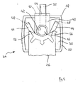
- An irritant sprayer carries in the FIGS. 1a and 1b It comprises a housing 12 for receiving a pressure vessel 14 and a spray head 18 placed on a delivery nipple 16 of the pressure vessel 14.
- the pressure vessel 14 and the spray head 18 form a total of an irritant cartridge 20, which is dashed and only in FIG. 1a is indicated.
- the housing 12 comprises at its top a hinged lid 22 which is articulated or pivotally mounted in 24.
- the irritant cartridge 20 is inserted into the housing 12 with the hinged lid 22 open and secured in the housing 12 by a locking element 26 in the form of a safety slide. This is in the in the FIGS. 1a and 1b shown mounting position releasably locked in the housing 12.
- an irritant is stored under pressure.
- an irritant pepper, capsaicin, Pelargonklallylamid, CS or CN gas or the like come into question.
- the pressure vessel 14 may also be filled with a neutral fluid, for example with pure water.
- the user grasps the housing 12 and pushes the thumb between the flip cover 22 and the spray head 18 so that the thumb rests on top of the spray head 18.
- the hinged lid 22 is raised slightly against the force of a spring, not shown.
- the user grabs the lower area of the Housing 12.
- the user presses with his thumb on a recessed and fluted actuating surface 28 of the spray head 18.
- the spray head 18 is moved toward the pressure vessel 14, whereby the dispensing valve, which is arranged in the pressure vessel 14, opens , whereby an irritant jet 30 exits from a spray nozzle 32 of the spray head 18.
- two blocking portions 44 are formed in the manner of laterally projecting wings.
- the blocking portions 44 are connected to the central portion 40 each via a thin material bridge 46.
- a nose 48 pointing towards the underside of the spray head 18 is formed in each case.
- the height of the protruding end of a Blocking portion 44 including the nose 48 corresponds approximately to the gap between the upper edge 38 of the pressure vessel 14 and the underside of an outer edge 50 of the spray head 18th
- the central portion 40 projects with its front edge slightly beyond the spray head 18. At this edge also facing away from the pressure vessel 14 nose 52 is formed, in the end region of a slot 54 is present. In this slot 54, the spray nozzle 32 is received. The depth of the slot 54 is chosen so that the spray head 18 for actuation of the irritant spray device 10 can continue to be moved sufficiently in the direction of the pressure vessel 14.
- FIG. 3 Furthermore, an area of the locking element 26 is shown. It can be seen that this has two lateral, in the longitudinal direction of the locking element 26 extending actuating portions 56.
- the blocking element 36 and then the spray head 18 are placed after filling it first.
- the blocking sections 44 are in the in the Figures 2 and 3 shown first position in which the lugs 48 are disposed between the edge 50 of the spray head 18 and the upper edge 38 of the pressure vessel 14 and thus prevent depression of the spray head 18 in the direction of the pressure vessel 14.
- the irritant cartridge 20 is inserted into the housing 12.
- the irritant cartridge 20 must be secured in the housing 12.
- the locking element 26 from a first position in which there is the pressure vessel 14 releases (about FIG. 3 ), in the FIG. 4 shown second position in which it secures the pressure vessel 14 in the housing 12.
- the lugs 48 are no longer between the outer edge 50 of the spray head 18 and the upper edge 38 of the pressure vessel 14, but below a space formed between the outer edge 50 of the spray head 18.
- the spray head 18 is moved toward the pressure vessel 14 and thereby an irritant jet 30 are triggered.
- Indicator 34 shown thus operates predominantly "tactile" in so far as the user can determine from the impossibility to depress the spray head 18, that a first startup in terms of producing a readiness for operation (“arming") has not yet occurred.
- arming By removing the pressure vessel 14 from the housing 12, he can also visually perceive the position of the blocking sections 44 visually.
- FIGS. 4 to 8 Another embodiment of a display device will now be described with reference to FIGS FIGS. 4 to 8 explained. In this case, it applies here and below that such elements and regions which are functionally equivalent to elements and regions of already described figures are usually not explained again in detail and bear the same reference numerals in all figures.
- the in the FIGS. 5 to 8 Display device 34 shown comprises a U-shaped sliding element 60 (see in particular FIG. 6 ), with a base 62 and two legs 64.
- the inner edges of the legs 64 are configured as friction surfaces 66.
- the clear width between the two legs 64 is selected so that the sliding element 60 is mounted in the installed position in a tight fit on the spray nozzle 32 by the spray nozzle 32 is received between the friction surfaces 66 of the two legs 64.
- FIG. 8 how out FIG. 8 it can be seen, are now the free ends of the two legs 64 on the top of the spray head 18 via. At this supernatant, the user can see that the spray head 18 has been actuated a first time.
- 60 colored markings 68 are present on the sliding element 60 ( FIG. 6 ), which in the in FIG. 5 hidden starting position of the spray head 18, in the in FIG. 8 However, the end position shown is free. These also help the user as an optical reference for the confirmation that the spray head 18 has already been depressed a first time.
- FIGS. 9 to 12 Another embodiment is in the FIGS. 9 to 12 shown.
- this two rod-shaped sliding elements 60 are present in the in the Figures 9 and 10 shown unused initial position in corresponding holes 70 are received in the spray head 18 such that in the figures upper end is substantially flush with the top of the spray head 18, whereas the lower end of the rod-shaped sliding elements 60 in the figures on a closure plate 71 of the pressure vessel 14 is supported.
- the sliding elements 60 are held in the holes 70 in frictional engagement.
- the spray head 18 When the spray head 18 is depressed for the first time by a user for the delivery of an irritant jet 30, the upper end of the rod-shaped sliding elements 60 in the figures slides out of the top of the spray head 18 (cf. FIG. 11 ). If the spray head 18 is released by the user, he returns to the in FIG. 12 shown starting position back. In this return movement, the two sliding elements 60 are taken from the spray head 18 due to the frictional engagement.
- the projection of the rod-shaped sliding members 60 over the top of the spray head 18 is a visual and tactile indication to the user that the spray head 18 has already been depressed at least once.
- FIG. 13 One to the FIGS. 9 to 12 very similar embodiment shows FIG. 13 In this, however, the rod-shaped sliding elements 60 are sunk in the unused initial position in the respective bore 70, so that they lie after a first use substantially flush with the top of the spray head 18.
- the two rod-shaped sliding elements 60 are each connected to the spray head 18 via a thin material bridge 46. The material bridge 46 breaks when the spray head 18 is depressed for the first time and the two sliding elements 60 are pressed in the respective bore 70 upwards.
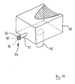
- FIG. 14 Another embodiment show the Figures 14 and 15
- the display device 34 shown there comprises a cover element 74, which is fastened to an annular end face 76 of the spray nozzle 32 with an adhesive before a first use of the irritant cartridge 20 of the irritant spray device.
- the end face 76 surrounds an outlet opening 78.
- the cover member 74 When the spray head 18 is depressed for the first time to deliver an irritant jet 30 from the irritant spray device 10 (FIG. FIG. 15 ), the cover member 74 is torn away from the end face 76 by the pressure of the irritant jet 30 (arrow 80 in FIG FIG. 15 ). It is therefore understood that the adhesive must be selected so that the pressure of the irritant jet 30 can entrain the cover 74 with certainty.
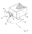
- the cover member 74 is made as a thin film or as a thin paper element and carries a signal color. The user can thus visually recognize in the presence or absence of the cover member 74 whether or not the irritant cartridge 20 has already been actuated and has delivered an irritant jet 30 or not.
- a tab is present on the cover 74, with the cover, if necessary, the cover 74 can be released by hand from the end face 76.
- the cover 74 includes a T-shaped cam portion 80, and on the housing 12, a corresponding abutment portion 82 is present.
- the driver portion 80 is slightly spaced from the stopper portion 82.
- the T-shaped cam portion 80 at the stop portion 82 of the housing 12 "hang", whereby the cover member 74 is released from the end face 76 of the spray nozzle 32. If the cover 74 is detached from the spray nozzle 32, it is in a "second position", but if it is still connected to the end face 76 of the spray nozzle 32, it is in a "first position".
- FIG. 18 This one is in the in FIG. 18 shown unactuated initial position on the recessed and fluted actuating surface 28, which may also be referred to as "engaging portion", a cover 84 stretched with a clamping portion 86.
- the clamping section 86 has a predetermined breaking point 88 in the form of a perforation.
Landscapes
- Engineering & Computer Science (AREA)
- Chemical & Material Sciences (AREA)
- Dispersion Chemistry (AREA)
- Mechanical Engineering (AREA)
- General Engineering & Computer Science (AREA)
- Containers And Packaging Bodies Having A Special Means To Remove Contents (AREA)
- Nozzles (AREA)
- Details Or Accessories Of Spraying Plant Or Apparatus (AREA)
Priority Applications (1)
| Application Number | Priority Date | Filing Date | Title |
|---|---|---|---|
| DE202009018089U DE202009018089U1 (de) | 2008-05-23 | 2009-04-17 | Reizstoff-Sprühgerät |
Applications Claiming Priority (1)
| Application Number | Priority Date | Filing Date | Title |
|---|---|---|---|
| DE102008024768A DE102008024768A1 (de) | 2008-05-23 | 2008-05-23 | Reizstoff-Sprühgerät |
Publications (2)
| Publication Number | Publication Date |
|---|---|
| EP2124013A2 true EP2124013A2 (fr) | 2009-11-25 |
| EP2124013A3 EP2124013A3 (fr) | 2010-04-28 |
Family
ID=40579699
Family Applications (1)
| Application Number | Title | Priority Date | Filing Date |
|---|---|---|---|
| EP09005450A Withdrawn EP2124013A3 (fr) | 2008-05-23 | 2009-04-17 | Pulvérisateur de gaz lacrimogène |
Country Status (2)
| Country | Link |
|---|---|
| EP (1) | EP2124013A3 (fr) |
| DE (2) | DE102008024768A1 (fr) |
Cited By (3)
| Publication number | Priority date | Publication date | Assignee | Title |
|---|---|---|---|---|
| EP2314979A1 (fr) * | 2009-10-21 | 2011-04-27 | Carl Hoernecke Chem. Fabrik GmbH & Co. KG | Appareil de pulvérisation de matière irritante |
| US9051108B2 (en) | 2010-05-21 | 2015-06-09 | S.C. Johnson & Son, Inc. | Shroud and dispensing system for a handheld container |
| US9211994B2 (en) | 2010-05-21 | 2015-12-15 | S.C. Johnson & Son, Inc. | Shroud and dispensing system for a handheld container |
Families Citing this family (2)
| Publication number | Priority date | Publication date | Assignee | Title |
|---|---|---|---|---|
| DE102015213144A1 (de) * | 2015-07-14 | 2017-01-19 | KKS GmbH | Sprühkopf und Sprühvorrichtung mit Sprühkopf |
| DE102018101238B4 (de) | 2018-01-19 | 2026-02-19 | Carl Hoernecke Chem. Fabrik Gmbh & Co. Kg | Wirkstoffpatrone sowie Selbstverteidigungsgerät |
Family Cites Families (10)
| Publication number | Priority date | Publication date | Assignee | Title |
|---|---|---|---|---|
| NL267775A (fr) * | 1959-08-05 | |||
| FR1433036A (fr) * | 1964-04-27 | 1966-03-25 | Avon Prod Inc | Pulvérisateur |
| FR2219623A5 (fr) * | 1973-02-26 | 1974-09-20 | Reboul Sa Sofra | |
| FR2495580A1 (fr) * | 1980-09-05 | 1982-06-11 | Oreal | Capot de distribution realise d'une seule piece pour recipient pressurise et ensemble correspondant |
| FR2673608A1 (fr) * | 1991-03-07 | 1992-09-11 | Chanel | Distributeur de produit comprenant des moyens d'inviolabilite. |
| US6595393B1 (en) * | 2002-01-07 | 2003-07-22 | Zarc International, Inc. | Spray delivery system and method for aerosol products |
| FR2860771B1 (fr) * | 2003-10-09 | 2006-03-03 | Valois Sas | Tete de distribution de produit fluide et procede de fabrication d'une telle tete |
| DE202006000889U1 (de) | 2006-01-20 | 2006-03-23 | Hoernecke, Carl | Aufnahmevorrichtung für eine Reizstoffpatrone, sowie Reizstoff-Sprühgerät |
| DE202006004268U1 (de) | 2006-03-17 | 2006-05-11 | Hoernecke, Carl | Reizstoff-Sprühgerät |
| DE202006008367U1 (de) | 2006-05-26 | 2006-07-27 | Hoernecke, Carl | Reizstoff-Sprühgerät |
-
2008
- 2008-05-23 DE DE102008024768A patent/DE102008024768A1/de not_active Ceased
-
2009
- 2009-04-17 DE DE202009018089U patent/DE202009018089U1/de not_active Expired - Lifetime
- 2009-04-17 EP EP09005450A patent/EP2124013A3/fr not_active Withdrawn
Cited By (3)
| Publication number | Priority date | Publication date | Assignee | Title |
|---|---|---|---|---|
| EP2314979A1 (fr) * | 2009-10-21 | 2011-04-27 | Carl Hoernecke Chem. Fabrik GmbH & Co. KG | Appareil de pulvérisation de matière irritante |
| US9051108B2 (en) | 2010-05-21 | 2015-06-09 | S.C. Johnson & Son, Inc. | Shroud and dispensing system for a handheld container |
| US9211994B2 (en) | 2010-05-21 | 2015-12-15 | S.C. Johnson & Son, Inc. | Shroud and dispensing system for a handheld container |
Also Published As
| Publication number | Publication date |
|---|---|
| DE202009018089U1 (de) | 2011-02-03 |
| DE102008024768A1 (de) | 2009-11-26 |
| EP2124013A3 (fr) | 2010-04-28 |
Similar Documents
| Publication | Publication Date | Title |
|---|---|---|
| EP2162172B1 (fr) | Instrument d'injection à usage unique comprenant au moins une barre de pression et un capuchon de fermeture | |
| DE102007031630B3 (de) | Einweginjektor mit mindestens einem Stützstab | |
| DE19502929B4 (de) | Aufblasvorrichtung, insbesondere für Rettungswesten | |
| EP1667754A1 (fr) | Dispositif d'administration comportant un systeme d'insertion et un systeme de distribution | |
| DE6608621U (de) | Vorrichtung zum abgeben von aerosolen. | |
| DE60302218T2 (de) | Ausgabegerät zur aufnahme einer kartusche mit zurückschiebbaren stiften | |
| DE3640704C2 (fr) | ||
| EP4166239B1 (fr) | Distributeur de bouteilles compressibles à sécurité d'actionnement | |
| EP2124013A2 (fr) | Pulvérisateur de gaz lacrimogène | |
| EP3909464A1 (fr) | Applicateur masseur | |
| DE102007032464A1 (de) | Einweginjektor mit mindestens einem Zughaken | |
| DE69701636T2 (de) | Sprühkopf für aerosoldosen | |
| EP0583746A1 (fr) | Dispositif d'indication pour un appareil de gonflage, notamment pour un conteneur ou un flotteur d'un ensemble de sauvetage | |
| DE102010013543B3 (de) | Austragvorrichtung für Flüssigkeiten | |
| EP3441324B1 (fr) | Distributeur de liquide permettant de distribuer un liquide pourvu d'un réservoir supplémentaire pour un milieu supplémentaire | |
| DE102006036517A1 (de) | Abgabekopf für einen ein fließfähiges Medium unter Druck aufnehmenden Druckbehälter | |
| EP1836104B1 (fr) | Recipient sous pression destine a distribuer une substance a plusieurs composants contenue dans ledit recipient | |
| EP1900652A1 (fr) | Conteneur | |
| EP4412944A1 (fr) | Dispositif de prélèvement et de régulation destiné à soutirer un liquide d'un récipient | |
| EP4440358A1 (fr) | Distributeur de liquide et cartouche de liquide pour un distributeur de liquide de ce type | |
| DE102006005784A1 (de) | Spritze | |
| EP3974345A1 (fr) | Tête de pulvérisation et distributeur doté d'une telle tête de pulvérisation | |
| EP2314979B1 (fr) | Appareil de pulvérisation de matière irritante | |
| DE102004042503B3 (de) | Verschluss mit Foliendurchstech-Einrichtung für einen Behälter | |
| DE102018101238A1 (de) | Wirkstoffpatrone sowie Selbstverteidigungsgerät |
Legal Events
| Date | Code | Title | Description |
|---|---|---|---|
| PUAI | Public reference made under article 153(3) epc to a published international application that has entered the european phase |
Free format text: ORIGINAL CODE: 0009012 |
|
| AK | Designated contracting states |
Kind code of ref document: A2 Designated state(s): AT BE BG CH CY CZ DE DK EE ES FI FR GB GR HR HU IE IS IT LI LT LU LV MC MK MT NL NO PL PT RO SE SI SK TR |
|
| PUAL | Search report despatched |
Free format text: ORIGINAL CODE: 0009013 |
|
| AK | Designated contracting states |
Kind code of ref document: A3 Designated state(s): AT BE BG CH CY CZ DE DK EE ES FI FR GB GR HR HU IE IS IT LI LT LU LV MC MK MT NL NO PL PT RO SE SI SK TR |
|
| AX | Request for extension of the european patent |
Extension state: AL BA RS |
|
| STAA | Information on the status of an ep patent application or granted ep patent |
Free format text: STATUS: THE APPLICATION IS DEEMED TO BE WITHDRAWN |
|
| 18D | Application deemed to be withdrawn |
Effective date: 20101029 |