EP2124126A2 - Verriegelungsmechanismus für einen Drehknopf - Google Patents
Verriegelungsmechanismus für einen Drehknopf Download PDFInfo
- Publication number
- EP2124126A2 EP2124126A2 EP09160680A EP09160680A EP2124126A2 EP 2124126 A2 EP2124126 A2 EP 2124126A2 EP 09160680 A EP09160680 A EP 09160680A EP 09160680 A EP09160680 A EP 09160680A EP 2124126 A2 EP2124126 A2 EP 2124126A2
- Authority
- EP
- European Patent Office
- Prior art keywords
- device shaft
- knob
- control knob
- shaft
- angled
- Prior art date
- Legal status (The legal status is an assumption and is not a legal conclusion. Google has not performed a legal analysis and makes no representation as to the accuracy of the status listed.)
- Granted
Links
Images


Classifications
-
- B—PERFORMING OPERATIONS; TRANSPORTING
- B21—MECHANICAL METAL-WORKING WITHOUT ESSENTIALLY REMOVING MATERIAL; PUNCHING METAL
- B21C—MANUFACTURE OF METAL SHEETS, WIRE, RODS, TUBES, PROFILES OR LIKE SEMI-MANUFACTURED PRODUCTS OTHERWISE THAN BY ROLLING; AUXILIARY OPERATIONS USED IN CONNECTION WITH METAL-WORKING WITHOUT ESSENTIALLY REMOVING MATERIAL
- B21C37/00—Manufacture of metal sheets, rods, wire, tubes, profiles or like semi-manufactured products, not otherwise provided for; Manufacture of tubes of special shape
- B21C37/06—Manufacture of metal sheets, rods, wire, tubes, profiles or like semi-manufactured products, not otherwise provided for; Manufacture of tubes of special shape of tubes or metal hoses; Combined procedures for making tubes, e.g. for making multi-wall tubes
- B21C37/08—Making tubes with welded or soldered seams
- B21C37/0815—Making tubes with welded or soldered seams without continuous longitudinal movement of the sheet during the bending operation
-
- B—PERFORMING OPERATIONS; TRANSPORTING
- B21—MECHANICAL METAL-WORKING WITHOUT ESSENTIALLY REMOVING MATERIAL; PUNCHING METAL
- B21D—WORKING OR PROCESSING OF SHEET METAL OR METAL TUBES, RODS OR PROFILES WITHOUT ESSENTIALLY REMOVING MATERIAL; PUNCHING METAL
- B21D5/00—Bending sheet metal along straight lines, e.g. to form simple curves
- B21D5/01—Bending sheet metal along straight lines, e.g. to form simple curves between rams and anvils or abutments
- B21D5/015—Bending sheet metal along straight lines, e.g. to form simple curves between rams and anvils or abutments for making tubes
-
- G—PHYSICS
- G05—CONTROLLING; REGULATING
- G05G—CONTROL DEVICES OR SYSTEMS INSOFAR AS CHARACTERISED BY MECHANICAL FEATURES ONLY
- G05G1/00—Controlling members, e.g. knobs or handles; Assemblies or arrangements thereof; Indicating position of controlling members
- G05G1/08—Controlling members for hand actuation by rotary movement, e.g. hand wheels
- G05G1/10—Details, e.g. of discs, knobs, wheels or handles
- G05G1/12—Means for securing the members on rotatable spindles or the like
-
- Y—GENERAL TAGGING OF NEW TECHNOLOGICAL DEVELOPMENTS; GENERAL TAGGING OF CROSS-SECTIONAL TECHNOLOGIES SPANNING OVER SEVERAL SECTIONS OF THE IPC; TECHNICAL SUBJECTS COVERED BY FORMER USPC CROSS-REFERENCE ART COLLECTIONS [XRACs] AND DIGESTS
- Y10—TECHNICAL SUBJECTS COVERED BY FORMER USPC
- Y10T—TECHNICAL SUBJECTS COVERED BY FORMER US CLASSIFICATION
- Y10T74/00—Machine element or mechanism
- Y10T74/20—Control lever and linkage systems
- Y10T74/20576—Elements
- Y10T74/20732—Handles
- Y10T74/20834—Hand wheels
- Y10T74/2084—Knob or dial
Definitions
- the present invention generally relates to a knob securement assembly, and more particularly relates to a control knob and device shaft securement assembly that prevents loosening of the control knob from the device shaft during rotational and push/pull operations.
- Prior art remedies to this knob attachment issue include cutting a groove into and circumferentially about the encoder shaft.
- the fabrication of this type of groove into the encoder shaft may prevent loosening of the knob due to pushing and pulling, but it does not address the rotational issue.
- a circumferentially defined groove does not allow for adjustment with respect to alignment of the knob relative to the front panel positioned between the knob and switch assembly, and thus compensation for any tolerances in the panel thickness.
- the groove is formed circumferentially about the shaft, determines the in/out positioning of the knob relative to the panel. This may cause an interference of the knob with the face of the panel if positioned too close.
- knob assembly and means of securing a knob to a shaft that eliminates loosening of the knob relative to the shaft during rotational and push/pull directional movement of the knob.
- a knob assembly and method of securing a knob to a shaft that provides some leeway during initial securement of the knob to the shaft due to tolerances in the front panel or mounting plate.
- the inventive subject matter provides a means for securing a knob to a device shaft that eliminates loosening of the knob relative to the device shaft during rotational and push/pull directional movement of the knob.
- an actuating device comprising a device shaft extending through an aperture in the control panel for rotation about an axis relative to the panel, and a control knob on the device shaft
- the control knob including a knob securement means comprising: a threaded bore in the control knob; a set screw disposed within the threaded bore for securing the control knob to the device shaft; and an angled groove having a plurality of angled side portions formed into a surface of an end portion of the device shaft, whereby cooperation of the set screw within the angled groove comprises adjustable securement of the control knob to the device shaft during rotation of the control knob and the device shaft.
- an actuating device comprising a device shaft extending through an aperture in the control panel for rotation about an axis relative to the panel, and a control knob on the device shaft
- the control knob including a knob securement means comprising: a threaded bore formed in a shank portion of the control knob; a cooperating set screw disposed within the threaded bore of the control knob for securing the control knob to the device shaft; and an angled groove having a plurality of angled side portions formed into a surface of an end portion of the device shaft, the angled groove formed into the surface at an angle between 10-80 degrees relative to a linear axis of the device shaft, whereby cooperation of the set screw within the angled groove comprises adjustable securement of the control knob to the device shaft during rotation of the control knob and device shaft.
- a means for securing a knob to a device shaft wherein the a device assembly comprises: an actuating device including a device shaft extending therefrom and configured for actuation of the actuating device upon movement of the device shaft rotationally about a linear axis of the device shaft or perpendicular to the linear axis of the device shaft; a control knob coupled to an end portion of the device shaft and configured to provide means for accomplishing movement of the device shaft; a means for securement of the control knob to the device shaft including an angled groove having angled side portions formed into the surface of the end portion of the device shaft and a cooperating set screw extending through a portion of the control knob, whereby the positioning of the set screw to contact the angled side portions of the angled groove comprises a securement means upon movement of the control knob and device shaft.
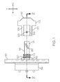
- FIG. 1 is a partial sectional view of a control device of an aircraft having a control knob positioned relative to a device shaft prior to securement, the control knob including a knob securement means according to an embodiment;
- FIG.2 is a sectional view of the assembly of FIG. 1 including the control knob secured to the device shaft according to an embodiment
- FIG.3 is a close up view of a portion of the device shaft and the angled groove formed therein according to an embodiment.
- the control assembly 100 includes a stationary front mounting plate or plate 110 for supporting electronic circuitry and control switches, and the like.
- a control knob 112 is positioned relative to the stationary front plate 110.
- a sectional view through the control knob 112 and the front plate 110 in an assembled or secured state is shown in FIG. 2 .
- An actuating device 114 such as a switch or encoder device, is mounted to the front plate 110 with a mounting bolt 116, or the like.
- a substantially circular device shaft 118 extending from the actuating device or encoder device 114 is positioned extending through an aperture 120 formed in the front plate 110.
- control knob 112 includes a shank 122 and head portion 113. Although a specific design for control knob 112 is depicted in the FIGs. it should be understood that any shape knob configured for use with the device shaft 118 is anticipated.
- the shank 122 includes a bore 124 formed therein and extending parallel with the linear axis of the shank 122.
- the bore 124 is substantially shaped to conform to the shape of the device shaft 118.
- a threaded bore 125 formed in a sidewall 123 of the shank 122 and substantially perpendicular to the bore 124 provides for the insertion of a set screw 126 extending through the sidewall 123 of the shank 122 and contacting the device shaft 118.
- the set screw 126 provides conventional retention function to secure the control knob 112 on the device shaft 118.
- an angled groove 130 is formed in the device shaft 118. More specifically, the angled groove 130 is formed into a surface 119 of an end portion 121 of the device shaft 118 and at an angle to the linear axis, illustrated in FIG. 2 . In a preferred embodiment, the angled groove 130 is formed at an angle of between 10-80 degrees relative to the linear axis of the device shaft 118, and at a preferred angle of 45 degrees relative to the linear axis of the device shaft 118. As best shown in FIG. 3 , the angled groove 130 includes a plurality of angled sides 132 so as to form a substantially v-shaped groove cut into the surface of the device shaft 118.
- the control knob 112 is positioned onto the device shaft 118, and more particularly, the device shaft 118 is inserted into the bore 124 formed in the control knob 112 whereby the set screw 126 is substantially aligned with the angled groove 130.
- the control knob 112 is properly positioned a distance "a" from the mounting plate 110 as illustrated in FIG. 1 .
- Secure retention of the control knob 112 is accomplished by tightening the set screw 126 so that it engages with the angled groove 130.
- the set screw 126 may include an angled tip 127 as illustrated in FIG. 2 , and more particularly angled circumferential side aspects, so that tight engagement with the angled sides 132 of the angled groove 130 is accomplished.
- the formation of the angled groove 130 at a relative angle to the linear axis of the device shaft 118 provides maximum retention force in both the "x" direction, when pushing or pulling the control knob 112 and in the "y” direction, when rotating the control knob 112 circumferentially about the linear axis of the device shaft 118.
- a knob assembly has now been provided to that is capable of being releasably secured to a shaft without becoming loose during movement of the knob.
- a means for adjustment of the knob relative to a mounting plate to provide for tolerances in the thickness of the mounting plate and assure a flush mount to the face of the mounting plate when desired. While the prior art has reported using knobs, none have established a basis for a specific knob securement design that is dedicated to the task of resolving the particular problem at hand.
Landscapes
- Engineering & Computer Science (AREA)
- Mechanical Engineering (AREA)
- Physics & Mathematics (AREA)
- General Physics & Mathematics (AREA)
- Automation & Control Theory (AREA)
- Mechanical Control Devices (AREA)
Applications Claiming Priority (1)
| Application Number | Priority Date | Filing Date | Title |
|---|---|---|---|
| US12/125,764 US20090288512A1 (en) | 2008-05-22 | 2008-05-22 | Knob securement means for a control device |
Publications (3)
| Publication Number | Publication Date |
|---|---|
| EP2124126A2 true EP2124126A2 (de) | 2009-11-25 |
| EP2124126A3 EP2124126A3 (de) | 2010-06-02 |
| EP2124126B1 EP2124126B1 (de) | 2011-10-26 |
Family
ID=41213489
Family Applications (1)
| Application Number | Title | Priority Date | Filing Date |
|---|---|---|---|
| EP09160680A Not-in-force EP2124126B1 (de) | 2008-05-22 | 2009-05-19 | Verriegelungsmechanismus für einen Drehknopf |
Country Status (3)
| Country | Link |
|---|---|
| US (1) | US20090288512A1 (de) |
| EP (1) | EP2124126B1 (de) |
| AT (1) | ATE530972T1 (de) |
Cited By (4)
| Publication number | Priority date | Publication date | Assignee | Title |
|---|---|---|---|---|
| CN105446415A (zh) * | 2015-11-03 | 2016-03-30 | 北京航科发动机控制系统科技有限公司 | 一种随动可调单向位置限制机构 |
| US20160114131A1 (en) * | 2013-02-12 | 2016-04-28 | St. Jude Medical, Atrial Fibrillation Division, Inc. | Elongate medical device handle autolock |
| US20180074542A1 (en) * | 2013-08-22 | 2018-03-15 | Anthony LIVOLSI | Fixed adjustment dial |
| CN109759481A (zh) * | 2018-11-26 | 2019-05-17 | 安徽省通快数控机床制造有限公司 | 一种卷板机 |
Families Citing this family (1)
| Publication number | Priority date | Publication date | Assignee | Title |
|---|---|---|---|---|
| US8575501B2 (en) | 2011-09-12 | 2013-11-05 | Whirlpool Corporation | Household appliance having a user interface with a user-exchangeable touch wheel and rotary encoder |
Family Cites Families (24)
| Publication number | Priority date | Publication date | Assignee | Title |
|---|---|---|---|---|
| US261968A (en) * | 1882-08-01 | Waeeen h | ||
| US299633A (en) * | 1884-06-03 | Door-knob attachment | ||
| US72597A (en) * | 1867-12-24 | Charles b | ||
| US133246A (en) * | 1872-11-19 | Improvement in securing pulleys to shafts | ||
| US1537227A (en) * | 1924-06-26 | 1925-05-12 | Wittla France Company De | Dial with universal connections |
| US1687531A (en) * | 1927-06-15 | 1928-10-16 | Firm Westfalische Metallwarenf | Knob and knoblike device |
| US2186678A (en) * | 1935-10-19 | 1940-01-09 | Yale & Towne Mfg Co | Knob securing means |
| US2153950A (en) * | 1937-07-19 | 1939-04-11 | Waddell Mfg Company | Knob attaching device |
| US2293615A (en) * | 1941-02-24 | 1942-08-18 | United Carr Fastener Corp | Knob attachment |
| US2457920A (en) * | 1946-09-06 | 1949-01-04 | John F Rider | Unitary volume-control switch and dialite assembly |
| US2935896A (en) * | 1958-06-30 | 1960-05-10 | Joseph E Simon | Replacement valve handle |
| US3120585A (en) * | 1958-12-09 | 1964-02-04 | Teleregister Corp | Rotary switch with replaceable contact sets |
| US3386127A (en) * | 1965-10-22 | 1968-06-04 | Mc Graw Edison Co | Control knob connecting means |
| FR2145052A5 (de) * | 1971-07-07 | 1973-02-16 | Condevaux Georges | |
| US3986409A (en) * | 1975-07-07 | 1976-10-19 | Raytheon Company | Push-to-engage device |
| US4433218A (en) * | 1981-08-17 | 1984-02-21 | Kidde, Inc. | Electrical instrument with removable calibrating knob |
| US5048365A (en) * | 1990-03-29 | 1991-09-17 | Magnavox Government And Industrial Electronics Company | Ordnance arming switch knob assembly |
| US5280973A (en) * | 1992-09-25 | 1994-01-25 | The United States Of America As Represented By The Secretary Of The Army | Hatch securing mechanism |
| US5862715A (en) * | 1995-12-18 | 1999-01-26 | Electronic Hardware Corp. | Tactile detent knob |
| US5950623A (en) * | 1997-10-16 | 1999-09-14 | Ohmeda Inc. | Adjustable pressure limiting valve for anesthesia breathing circuit |
| US6402351B1 (en) * | 1998-03-27 | 2002-06-11 | Hill-Rom Services, Inc., | Controls for a surgical light apparatus |
| DE10044448C2 (de) * | 2000-09-08 | 2003-09-11 | Bsh Bosch Siemens Hausgeraete | Drehschalteranordnung für ein Haushaltsgerät |
| US6343808B1 (en) * | 2000-12-11 | 2002-02-05 | Lenn Jianq Co., Ltd. | Trailer fastening device |
| US7000497B1 (en) * | 2002-04-22 | 2006-02-21 | Harry Edward Campbell | Selectively positionable gearshift and method |
-
2008
- 2008-05-22 US US12/125,764 patent/US20090288512A1/en not_active Abandoned
-
2009
- 2009-05-19 EP EP09160680A patent/EP2124126B1/de not_active Not-in-force
- 2009-05-19 AT AT09160680T patent/ATE530972T1/de not_active IP Right Cessation
Non-Patent Citations (1)
| Title |
|---|
| None |
Cited By (7)
| Publication number | Priority date | Publication date | Assignee | Title |
|---|---|---|---|---|
| US20160114131A1 (en) * | 2013-02-12 | 2016-04-28 | St. Jude Medical, Atrial Fibrillation Division, Inc. | Elongate medical device handle autolock |
| US10668250B2 (en) * | 2013-02-12 | 2020-06-02 | St. Jude Medical, Atrial Fibrillation Division, Inc. | Elongate medical device handle autolock |
| US20180074542A1 (en) * | 2013-08-22 | 2018-03-15 | Anthony LIVOLSI | Fixed adjustment dial |
| US10732664B2 (en) * | 2013-08-22 | 2020-08-04 | Anthony LIVOLSI | Fixed adjustment dial |
| CN105446415A (zh) * | 2015-11-03 | 2016-03-30 | 北京航科发动机控制系统科技有限公司 | 一种随动可调单向位置限制机构 |
| CN105446415B (zh) * | 2015-11-03 | 2017-03-01 | 北京航科发动机控制系统科技有限公司 | 一种随动可调单向位置限制机构 |
| CN109759481A (zh) * | 2018-11-26 | 2019-05-17 | 安徽省通快数控机床制造有限公司 | 一种卷板机 |
Also Published As
| Publication number | Publication date |
|---|---|
| EP2124126A3 (de) | 2010-06-02 |
| ATE530972T1 (de) | 2011-11-15 |
| US20090288512A1 (en) | 2009-11-26 |
| EP2124126B1 (de) | 2011-10-26 |
Similar Documents
| Publication | Publication Date | Title |
|---|---|---|
| EP2124126B1 (de) | Verriegelungsmechanismus für einen Drehknopf | |
| US6007136A (en) | Modular visor attachment fastener | |
| US8107257B2 (en) | Electronic assembly retaining system | |
| CA2296991C (en) | Fastener provided with a snapping-in foot to be pushed in through a hole in a panel | |
| DE102012221412B4 (de) | Einbauleuchte | |
| US8545143B2 (en) | Router with a cutting depth adjustment mechanism | |
| CN109196237B (zh) | 安装装置 | |
| US4715569A (en) | Fastening mechanism for mounting operating equipment and the like | |
| JP2022531665A (ja) | Dinレールのための可変幾何形状の設置用ブラケット | |
| JPH0969327A (ja) | 電磁スイッチにおけるターミナルハウジングの組付け構造 | |
| JP2005262337A (ja) | 切断機におけるライビングナイフの取り付け具 | |
| JPH048644A (ja) | 車載用機器の取付け装置 | |
| US7695029B2 (en) | Tolerance compensating device for rotating and tilting bolts | |
| US6592087B2 (en) | Mounting assembly for detection device | |
| US20170181308A1 (en) | Electronic unit hold down assembly | |
| US20050161568A1 (en) | Detector installing device | |
| US4253486A (en) | Control device mounting means and parts therefor | |
| US7325852B1 (en) | Cluster mounting bracket | |
| US4186762A (en) | Control device mounting means and parts therefor | |
| US7648213B2 (en) | Mechanism for fastening casing into wall opening | |
| JP7746316B2 (ja) | クリップ | |
| GB2108318A (en) | Switch with a case provided with an attaching device | |
| JP2006112105A (ja) | 車両用ドアハンドル装置 | |
| CN103635719B (zh) | 附连组件 | |
| US20240024971A1 (en) | Gap cutting double blade reciprocating saw attachment |
Legal Events
| Date | Code | Title | Description |
|---|---|---|---|
| PUAI | Public reference made under article 153(3) epc to a published international application that has entered the european phase |
Free format text: ORIGINAL CODE: 0009012 |
|
| 17P | Request for examination filed |
Effective date: 20090519 |
|
| AK | Designated contracting states |
Kind code of ref document: A2 Designated state(s): AT BE BG CH CY CZ DE DK EE ES FI FR GB GR HR HU IE IS IT LI LT LU LV MC MK MT NL NO PL PT RO SE SI SK TR |
|
| PUAL | Search report despatched |
Free format text: ORIGINAL CODE: 0009013 |
|
| AK | Designated contracting states |
Kind code of ref document: A3 Designated state(s): AT BE BG CH CY CZ DE DK EE ES FI FR GB GR HR HU IE IS IT LI LT LU LV MC MK MT NL NO PL PT RO SE SI SK TR |
|
| AX | Request for extension of the european patent |
Extension state: AL BA RS |
|
| 17Q | First examination report despatched |
Effective date: 20100708 |
|
| GRAP | Despatch of communication of intention to grant a patent |
Free format text: ORIGINAL CODE: EPIDOSNIGR1 |
|
| GRAC | Information related to communication of intention to grant a patent modified |
Free format text: ORIGINAL CODE: EPIDOSCIGR1 |
|
| GRAJ | Information related to disapproval of communication of intention to grant by the applicant or resumption of examination proceedings by the epo deleted |
Free format text: ORIGINAL CODE: EPIDOSDIGR1 |
|
| GRAP | Despatch of communication of intention to grant a patent |
Free format text: ORIGINAL CODE: EPIDOSNIGR1 |
|
| RIC1 | Information provided on ipc code assigned before grant |
Ipc: G05G 1/12 20060101AFI20110523BHEP |
|
| GRAS | Grant fee paid |
Free format text: ORIGINAL CODE: EPIDOSNIGR3 |
|
| GRAA | (expected) grant |
Free format text: ORIGINAL CODE: 0009210 |
|
| AK | Designated contracting states |
Kind code of ref document: B1 Designated state(s): AT BE BG CH CY CZ DE DK EE ES FI FR GB GR HR HU IE IS IT LI LT LU LV MC MK MT NL NO PL PT RO SE SI SK TR |
|
| REG | Reference to a national code |
Ref country code: GB Ref legal event code: FG4D |
|
| REG | Reference to a national code |
Ref country code: CH Ref legal event code: EP |
|
| REG | Reference to a national code |
Ref country code: IE Ref legal event code: FG4D |
|
| REG | Reference to a national code |
Ref country code: DE Ref legal event code: R096 Ref document number: 602009003263 Country of ref document: DE Effective date: 20111222 |
|
| REG | Reference to a national code |
Ref country code: NL Ref legal event code: VDEP Effective date: 20111026 |
|
| LTIE | Lt: invalidation of european patent or patent extension |
Effective date: 20111026 |
|
| REG | Reference to a national code |
Ref country code: AT Ref legal event code: MK05 Ref document number: 530972 Country of ref document: AT Kind code of ref document: T Effective date: 20111026 |
|
| PG25 | Lapsed in a contracting state [announced via postgrant information from national office to epo] |
Ref country code: IS Free format text: LAPSE BECAUSE OF FAILURE TO SUBMIT A TRANSLATION OF THE DESCRIPTION OR TO PAY THE FEE WITHIN THE PRESCRIBED TIME-LIMIT Effective date: 20120226 Ref country code: NO Free format text: LAPSE BECAUSE OF FAILURE TO SUBMIT A TRANSLATION OF THE DESCRIPTION OR TO PAY THE FEE WITHIN THE PRESCRIBED TIME-LIMIT Effective date: 20120126 Ref country code: LT Free format text: LAPSE BECAUSE OF FAILURE TO SUBMIT A TRANSLATION OF THE DESCRIPTION OR TO PAY THE FEE WITHIN THE PRESCRIBED TIME-LIMIT Effective date: 20111026 Ref country code: BE Free format text: LAPSE BECAUSE OF FAILURE TO SUBMIT A TRANSLATION OF THE DESCRIPTION OR TO PAY THE FEE WITHIN THE PRESCRIBED TIME-LIMIT Effective date: 20111026 |
|
| PG25 | Lapsed in a contracting state [announced via postgrant information from national office to epo] |
Ref country code: HR Free format text: LAPSE BECAUSE OF FAILURE TO SUBMIT A TRANSLATION OF THE DESCRIPTION OR TO PAY THE FEE WITHIN THE PRESCRIBED TIME-LIMIT Effective date: 20111026 Ref country code: PT Free format text: LAPSE BECAUSE OF FAILURE TO SUBMIT A TRANSLATION OF THE DESCRIPTION OR TO PAY THE FEE WITHIN THE PRESCRIBED TIME-LIMIT Effective date: 20120227 Ref country code: LV Free format text: LAPSE BECAUSE OF FAILURE TO SUBMIT A TRANSLATION OF THE DESCRIPTION OR TO PAY THE FEE WITHIN THE PRESCRIBED TIME-LIMIT Effective date: 20111026 Ref country code: GR Free format text: LAPSE BECAUSE OF FAILURE TO SUBMIT A TRANSLATION OF THE DESCRIPTION OR TO PAY THE FEE WITHIN THE PRESCRIBED TIME-LIMIT Effective date: 20120127 Ref country code: SE Free format text: LAPSE BECAUSE OF FAILURE TO SUBMIT A TRANSLATION OF THE DESCRIPTION OR TO PAY THE FEE WITHIN THE PRESCRIBED TIME-LIMIT Effective date: 20111026 Ref country code: PL Free format text: LAPSE BECAUSE OF FAILURE TO SUBMIT A TRANSLATION OF THE DESCRIPTION OR TO PAY THE FEE WITHIN THE PRESCRIBED TIME-LIMIT Effective date: 20111026 Ref country code: NL Free format text: LAPSE BECAUSE OF FAILURE TO SUBMIT A TRANSLATION OF THE DESCRIPTION OR TO PAY THE FEE WITHIN THE PRESCRIBED TIME-LIMIT Effective date: 20111026 Ref country code: SI Free format text: LAPSE BECAUSE OF FAILURE TO SUBMIT A TRANSLATION OF THE DESCRIPTION OR TO PAY THE FEE WITHIN THE PRESCRIBED TIME-LIMIT Effective date: 20111026 |
|
| PG25 | Lapsed in a contracting state [announced via postgrant information from national office to epo] |
Ref country code: CY Free format text: LAPSE BECAUSE OF FAILURE TO SUBMIT A TRANSLATION OF THE DESCRIPTION OR TO PAY THE FEE WITHIN THE PRESCRIBED TIME-LIMIT Effective date: 20111026 |
|
| PG25 | Lapsed in a contracting state [announced via postgrant information from national office to epo] |
Ref country code: DK Free format text: LAPSE BECAUSE OF FAILURE TO SUBMIT A TRANSLATION OF THE DESCRIPTION OR TO PAY THE FEE WITHIN THE PRESCRIBED TIME-LIMIT Effective date: 20111026 Ref country code: BG Free format text: LAPSE BECAUSE OF FAILURE TO SUBMIT A TRANSLATION OF THE DESCRIPTION OR TO PAY THE FEE WITHIN THE PRESCRIBED TIME-LIMIT Effective date: 20120126 Ref country code: SK Free format text: LAPSE BECAUSE OF FAILURE TO SUBMIT A TRANSLATION OF THE DESCRIPTION OR TO PAY THE FEE WITHIN THE PRESCRIBED TIME-LIMIT Effective date: 20111026 Ref country code: CZ Free format text: LAPSE BECAUSE OF FAILURE TO SUBMIT A TRANSLATION OF THE DESCRIPTION OR TO PAY THE FEE WITHIN THE PRESCRIBED TIME-LIMIT Effective date: 20111026 Ref country code: EE Free format text: LAPSE BECAUSE OF FAILURE TO SUBMIT A TRANSLATION OF THE DESCRIPTION OR TO PAY THE FEE WITHIN THE PRESCRIBED TIME-LIMIT Effective date: 20111026 |
|
| PG25 | Lapsed in a contracting state [announced via postgrant information from national office to epo] |
Ref country code: IT Free format text: LAPSE BECAUSE OF FAILURE TO SUBMIT A TRANSLATION OF THE DESCRIPTION OR TO PAY THE FEE WITHIN THE PRESCRIBED TIME-LIMIT Effective date: 20111026 Ref country code: RO Free format text: LAPSE BECAUSE OF FAILURE TO SUBMIT A TRANSLATION OF THE DESCRIPTION OR TO PAY THE FEE WITHIN THE PRESCRIBED TIME-LIMIT Effective date: 20111026 |
|
| PLBE | No opposition filed within time limit |
Free format text: ORIGINAL CODE: 0009261 |
|
| STAA | Information on the status of an ep patent application or granted ep patent |
Free format text: STATUS: NO OPPOSITION FILED WITHIN TIME LIMIT |
|
| 26N | No opposition filed |
Effective date: 20120727 |
|
| REG | Reference to a national code |
Ref country code: DE Ref legal event code: R097 Ref document number: 602009003263 Country of ref document: DE Effective date: 20120727 |
|
| PG25 | Lapsed in a contracting state [announced via postgrant information from national office to epo] |
Ref country code: MC Free format text: LAPSE BECAUSE OF NON-PAYMENT OF DUE FEES Effective date: 20120531 |
|
| PG25 | Lapsed in a contracting state [announced via postgrant information from national office to epo] |
Ref country code: AT Free format text: LAPSE BECAUSE OF FAILURE TO SUBMIT A TRANSLATION OF THE DESCRIPTION OR TO PAY THE FEE WITHIN THE PRESCRIBED TIME-LIMIT Effective date: 20111026 |
|
| REG | Reference to a national code |
Ref country code: IE Ref legal event code: MM4A |
|
| PG25 | Lapsed in a contracting state [announced via postgrant information from national office to epo] |
Ref country code: MK Free format text: LAPSE BECAUSE OF FAILURE TO SUBMIT A TRANSLATION OF THE DESCRIPTION OR TO PAY THE FEE WITHIN THE PRESCRIBED TIME-LIMIT Effective date: 20111026 |
|
| PG25 | Lapsed in a contracting state [announced via postgrant information from national office to epo] |
Ref country code: ES Free format text: LAPSE BECAUSE OF FAILURE TO SUBMIT A TRANSLATION OF THE DESCRIPTION OR TO PAY THE FEE WITHIN THE PRESCRIBED TIME-LIMIT Effective date: 20120206 Ref country code: IE Free format text: LAPSE BECAUSE OF NON-PAYMENT OF DUE FEES Effective date: 20120519 |
|
| PG25 | Lapsed in a contracting state [announced via postgrant information from national office to epo] |
Ref country code: FI Free format text: LAPSE BECAUSE OF FAILURE TO SUBMIT A TRANSLATION OF THE DESCRIPTION OR TO PAY THE FEE WITHIN THE PRESCRIBED TIME-LIMIT Effective date: 20111026 |
|
| PG25 | Lapsed in a contracting state [announced via postgrant information from national office to epo] |
Ref country code: MT Free format text: LAPSE BECAUSE OF FAILURE TO SUBMIT A TRANSLATION OF THE DESCRIPTION OR TO PAY THE FEE WITHIN THE PRESCRIBED TIME-LIMIT Effective date: 20111026 |
|
| REG | Reference to a national code |
Ref country code: CH Ref legal event code: PL |
|
| PG25 | Lapsed in a contracting state [announced via postgrant information from national office to epo] |
Ref country code: CH Free format text: LAPSE BECAUSE OF NON-PAYMENT OF DUE FEES Effective date: 20130531 Ref country code: LI Free format text: LAPSE BECAUSE OF NON-PAYMENT OF DUE FEES Effective date: 20130531 |
|
| PG25 | Lapsed in a contracting state [announced via postgrant information from national office to epo] |
Ref country code: TR Free format text: LAPSE BECAUSE OF FAILURE TO SUBMIT A TRANSLATION OF THE DESCRIPTION OR TO PAY THE FEE WITHIN THE PRESCRIBED TIME-LIMIT Effective date: 20111026 |
|
| PG25 | Lapsed in a contracting state [announced via postgrant information from national office to epo] |
Ref country code: LU Free format text: LAPSE BECAUSE OF NON-PAYMENT OF DUE FEES Effective date: 20120519 |
|
| PG25 | Lapsed in a contracting state [announced via postgrant information from national office to epo] |
Ref country code: HU Free format text: LAPSE BECAUSE OF FAILURE TO SUBMIT A TRANSLATION OF THE DESCRIPTION OR TO PAY THE FEE WITHIN THE PRESCRIBED TIME-LIMIT Effective date: 20090519 |
|
| REG | Reference to a national code |
Ref country code: FR Ref legal event code: PLFP Year of fee payment: 8 |
|
| REG | Reference to a national code |
Ref country code: FR Ref legal event code: PLFP Year of fee payment: 9 |
|
| REG | Reference to a national code |
Ref country code: FR Ref legal event code: PLFP Year of fee payment: 10 |
|
| PGFP | Annual fee paid to national office [announced via postgrant information from national office to epo] |
Ref country code: DE Payment date: 20200529 Year of fee payment: 12 Ref country code: FR Payment date: 20200528 Year of fee payment: 12 |
|
| PGFP | Annual fee paid to national office [announced via postgrant information from national office to epo] |
Ref country code: GB Payment date: 20200528 Year of fee payment: 12 |
|
| REG | Reference to a national code |
Ref country code: DE Ref legal event code: R119 Ref document number: 602009003263 Country of ref document: DE |
|
| GBPC | Gb: european patent ceased through non-payment of renewal fee |
Effective date: 20210519 |
|
| PG25 | Lapsed in a contracting state [announced via postgrant information from national office to epo] |
Ref country code: GB Free format text: LAPSE BECAUSE OF NON-PAYMENT OF DUE FEES Effective date: 20210519 Ref country code: DE Free format text: LAPSE BECAUSE OF NON-PAYMENT OF DUE FEES Effective date: 20211201 |
|
| PG25 | Lapsed in a contracting state [announced via postgrant information from national office to epo] |
Ref country code: FR Free format text: LAPSE BECAUSE OF NON-PAYMENT OF DUE FEES Effective date: 20210531 |
|
| P01 | Opt-out of the competence of the unified patent court (upc) registered |
Effective date: 20230525 |