EP2124138B1 - Terminal mobile utilisant un détecteur de proximité - Google Patents
Terminal mobile utilisant un détecteur de proximité Download PDFInfo
- Publication number
- EP2124138B1 EP2124138B1 EP09006851.1A EP09006851A EP2124138B1 EP 2124138 B1 EP2124138 B1 EP 2124138B1 EP 09006851 A EP09006851 A EP 09006851A EP 2124138 B1 EP2124138 B1 EP 2124138B1
- Authority
- EP
- European Patent Office
- Prior art keywords
- proximity
- touch
- screen
- mobile terminal
- pointer
- Prior art date
- Legal status (The legal status is an assumption and is not a legal conclusion. Google has not performed a legal analysis and makes no representation as to the accuracy of the status listed.)
- Active
Links
Images







Classifications
-
- G—PHYSICS
- G06—COMPUTING OR CALCULATING; COUNTING
- G06F—ELECTRIC DIGITAL DATA PROCESSING
- G06F3/00—Input arrangements for transferring data to be processed into a form capable of being handled by the computer; Output arrangements for transferring data from processing unit to output unit, e.g. interface arrangements
- G06F3/01—Input arrangements or combined input and output arrangements for interaction between user and computer
- G06F3/03—Arrangements for converting the position or the displacement of a member into a coded form
- G06F3/041—Digitisers, e.g. for touch screens or touch pads, characterised by the transducing means
- G06F3/044—Digitisers, e.g. for touch screens or touch pads, characterised by the transducing means by capacitive means
-
- G—PHYSICS
- G06—COMPUTING OR CALCULATING; COUNTING
- G06F—ELECTRIC DIGITAL DATA PROCESSING
- G06F3/00—Input arrangements for transferring data to be processed into a form capable of being handled by the computer; Output arrangements for transferring data from processing unit to output unit, e.g. interface arrangements
- G06F3/01—Input arrangements or combined input and output arrangements for interaction between user and computer
- G06F3/03—Arrangements for converting the position or the displacement of a member into a coded form
- G06F3/033—Pointing devices displaced or positioned by the user, e.g. mice, trackballs, pens or joysticks; Accessories therefor
- G06F3/039—Accessories therefor, e.g. mouse pads
- G06F3/0393—Accessories for touch pads or touch screens, e.g. mechanical guides added to touch screens for drawing straight lines, hard keys overlaying touch screens or touch pads
-
- G—PHYSICS
- G06—COMPUTING OR CALCULATING; COUNTING
- G06F—ELECTRIC DIGITAL DATA PROCESSING
- G06F3/00—Input arrangements for transferring data to be processed into a form capable of being handled by the computer; Output arrangements for transferring data from processing unit to output unit, e.g. interface arrangements
- G06F3/01—Input arrangements or combined input and output arrangements for interaction between user and computer
- G06F3/048—Interaction techniques based on graphical user interfaces [GUI]
- G06F3/0487—Interaction techniques based on graphical user interfaces [GUI] using specific features provided by the input device, e.g. functions controlled by the rotation of a mouse with dual sensing arrangements, or of the nature of the input device, e.g. tap gestures based on pressure sensed by a digitiser
- G06F3/0488—Interaction techniques based on graphical user interfaces [GUI] using specific features provided by the input device, e.g. functions controlled by the rotation of a mouse with dual sensing arrangements, or of the nature of the input device, e.g. tap gestures based on pressure sensed by a digitiser using a touch-screen or digitiser, e.g. input of commands through traced gestures
- G06F3/04883—Interaction techniques based on graphical user interfaces [GUI] using specific features provided by the input device, e.g. functions controlled by the rotation of a mouse with dual sensing arrangements, or of the nature of the input device, e.g. tap gestures based on pressure sensed by a digitiser using a touch-screen or digitiser, e.g. input of commands through traced gestures for inputting data by handwriting, e.g. gesture or text
-
- G—PHYSICS
- G06—COMPUTING OR CALCULATING; COUNTING
- G06F—ELECTRIC DIGITAL DATA PROCESSING
- G06F2203/00—Indexing scheme relating to G06F3/00 - G06F3/048
- G06F2203/041—Indexing scheme relating to G06F3/041 - G06F3/045
- G06F2203/04101—2.5D-digitiser, i.e. digitiser detecting the X/Y position of the input means, finger or stylus, also when it does not touch, but is proximate to the digitiser's interaction surface and also measures the distance of the input means within a short range in the Z direction, possibly with a separate measurement setup
-
- G—PHYSICS
- G06—COMPUTING OR CALCULATING; COUNTING
- G06F—ELECTRIC DIGITAL DATA PROCESSING
- G06F2203/00—Indexing scheme relating to G06F3/00 - G06F3/048
- G06F2203/041—Indexing scheme relating to G06F3/041 - G06F3/045
- G06F2203/04108—Touchless 2D- digitiser, i.e. digitiser detecting the X/Y position of the input means, finger or stylus, also when it does not touch, but is proximate to the digitiser's interaction surface without distance measurement in the Z direction
Definitions
- the present invention relates to a mobile terminal capable of controlling a display screen by use of a touching function, and a display screen (wallpaper) controlling method thereof.
- Mobile terminals may be configured to perform various functions, for example, data and voice communication, capturing images or video, storing voice, reproducing music files via a speaker system, displaying images or video and the like. Some of mobile terminals may include an additional function of playing games, and other mobile terminals may be implemented as multimedia players. In addition, in recent time, mobile terminals can receive broadcast or multicast signals to allow viewing of video or television programs.
- a touch function of the mobile terminal allows even users, who are not familiar to input buttons or keys, to conveniently operate the mobile terminal using a touch screen.
- a touch function is being established as an important function of the mobile terminal together with a user interface (UI).
- US 2008/012835 discloses that, when calibrating a proximity sensor, the user is asked to position one or more fingers at one or more specified heights over the digitizer sensor, and signal amplitudes at the specified heights are stored to determine absolute heights during a user's operation of the system.
- WO 2003/073254 discloses to display on a touch screen, next to a pointer icon, an image of the user's hand so that the user knows how to position his hand to make an input.
- the size of the displayed hand is increased as the user moves the hand farther away, to indicate an increased inaccuracy when making inputs.
- a circle of varying size may be displayed in a corner of the display to provide an indication of a distance of the user's hand from the display.
- US 5,410,488 discloses to test a proximity sensor for proper operation by sensing impedance while the sensor and the target are separated by a dielectric spacer having a known width.
- US 2008/106520 discloses a method of calibrating detection of a proximity of a stylus including sensing a position of a stylus mounted in a stylus holder on an x-motion stage and moving the stylus in a direction toward the touch screen.
- WO 2006/003588 discloses a graphical user interface with 3D sensing, wherein a user can select icons using a proximity touch .
- an object of the present invention is to provide a mobile terminal capable of calibrating a touch recognition rate upon controlling operations of objects and displaying effects on a screen.
- a mobile terminal including a display for displaying a plurality of objects on a touch screen, a sensing unit for detecting a real touch on a surface contact point of the touch screen and a proximity touch of a pointer, and a controller for calibrating recognition rates generated due to a difference of capacitances upon the pointer inputting a proximity touch at a maximum proximity position and at a minimum proximity position, according to a sensing signal provided from the sensing unit.
- the controller may display reference figures indicating the maximum proximity position and the minimum proximity position and a guide figure increased or decreased in size in cooperation with the movement of the pointer, thus to set a maximum capacitance and a minimum capacitance when the size of the guide figure is the same to that of the reference figures.
- the controller may display a reference figure indicating a minimum proximity position when a real touch is detected and a guide figure increased in size in cooperation with the movement of the pointer, while displaying a reference figure indicating a maximum proximity position when a proximity touch is detected, and a guide figure decreased in size in cooperation with the movement of the pointer.
- the objects may include icons, avatars and menus, and the screen may be a wallpaper configured in a form of animation or flash.
- the operations relating to the objects may include sizes, movement speeds, movements, vibration and effect sounds of the objects.
- the controller may control the objects to be differently displayed according to proximity position and proximity speed, and display an object hidden in a corresponding position when the pointer comes close to a predetermined region of the screen.
- FIG. 1 is a block diagram of a mobile terminal in accordance with one embodiment of the present invention.
- a mobile terminal may be implemented in various types of terminals. Examples of such terminals described in this specification may include mobile phones, smart phones, notebook computers, digital broadcast terminals, Personal Digital Assistants (PDA), Portable Multimedia Players (PMP), navigators and the like.
- PDA Personal Digital Assistants
- PMP Portable Multimedia Players
- a mobile terminal 100 shown in FIG. 1 may include components, such as a wireless communication unit 110, an Audio/Video (A/V) input unit 120, a user input unit 130, a sensing unit 140, an output unit 150, a memory 160, an interface unit 170, a controller 180, a power supply 190 and the like.
- FIG. 1 shows the mobile terminal 100 having various components, but it is understood that implementing all of the illustrated components is not a requirement. Greater or fewer components may alternatively be implemented.
- the wireless communication unit 110 may typically include one or more components which permit wireless communications between the mobile terminal 100 and a wireless communication system or between the mobile terminal 100 and a network within which the mobile terminal 100 is located.
- the wireless communication unit 110 may include at least one of a broadcast receiving module 111, a mobile communication module 112, a wireless internet module 113, a short-range communication module 114 and a position location module 115.
- the broadcast receiving module 111 receives a broadcast signal and/or broadcast associated information from an external broadcast managing entity via a broadcast channel.
- the broadcast channel may include a satellite channel and a terrestrial channel.
- the broadcast managing entity may indicate a server which generates and transmits a broadcast signal and/or broadcast associated information or a server which receives a pre-generated broadcast signal and/or broadcast associated information and sends them to the mobile terminal.
- Examples of broadcast associated information may include information associated with a broadcast channel, a broadcast program, a broadcast service provider, and the like.
- the broadcast signal may be implemented as a TV broadcast signal, a radio broadcast signal, and a data broadcast signal, among others.
- the broadcast signal may further include a data broadcast signal combined with a TV or radio broadcast signal.
- the broadcast associated information may be provided via a mobile communication network, and received by the mobile communication module 112.
- broadcast associated information may be implemented in various formats.
- broadcast associated information may include Electronic Program Guide (EPG) of Digital Multimedia Broadcasting (DMB), Electronic Service Guide (ESG) of Digital Video Broadcast-Handheld (DVB-H), and the like.
- EPG Electronic Program Guide
- DMB Digital Multimedia Broadcasting
- ESG Electronic Service Guide
- DVD-H Digital Video Broadcast-Handheld
- the broadcast receiving module 111 may be configured to receive digital broadcast signals transmitted from various types of broadcast systems. Such broadcast systems may include Digital Multimedia Broadcasting-Terrestrial (DMB-T), Digital Multimedia Broadcasting-Satellite (DMB-S), Media Forward Link Only (MediaFLO), Digital Video Broadcast-Handheld (DVB-H), Integrated Services Digital Broadcast-Terrestrial (ISDB-T), and the like.
- the broadcast receiving module 111 may be configured to be suitable for every broadcast system transmitting broadcast signals as well as the digital broadcasting systems.
- Broadcast signals and/or broadcast associated information received via the broadcast receiving module 111 may be stored in a suitable device, such as a memory 160.
- the mobile communication module 112 transmits/receives wireless signals to/from at least one of network entities (e.g., base station, an external mobile terminal, a server, etc.) on a mobile communication network.
- the wireless signals may include audio call signal, video call signal, or various formats of data according to transmission/reception of text/multimedia messages.
- the wireless internet module 113 supports wireless Internet access for the mobile terminal. This module may be internally or externally coupled to the mobile terminal.
- the short-range communication module 114 denotes a module for short-range communications. Suitable technologies for implementing this module may include BLUETOOTH, Radio Frequency IDentification (RFID), Infrared Data Association (IrDA), Ultra-WideBand (UWB), ZigBee, and the like.
- RFID Radio Frequency IDentification
- IrDA Infrared Data Association
- UWB Ultra-WideBand
- ZigBee ZigBee
- the position location module 115 denotes a module for detecting or calculating a position of a mobile terminal.
- An example of the position location module 115 may include a Global Position System (GPS) module.
- GPS Global Position System
- the GPS module may receive position information in cooperation with associated multiple satellites.
- the position information may include coordinates information represented by latitude and longitude.
- the GPS module can measure accurate time and distance respectively from more than three satellites so as to accurately calculate a current position of the mobile terminal based on such three different distances according to a triangulation scheme.
- a scheme maybe used to obtain time information and distance information from three satellites and correct error by one satellite.
- the GPS module can further obtain three-dimensional speed information and an accurate time, as well as position on latitude, longitude and altitude, from the position information received from the satellites.
- the A/V input unit 120 is configured to provide audio or video signal input to the mobile terminal.
- the A/V input unit 120 may include a camera 121 and a microphone 122.
- the camera 121 receives and processes image frames of still pictures or video obtained by image sensors in a video call mode or a capturing mode. The processed image frames may be displayed on a display 151.
- the image frames processed by the camera 121 may be stored in the memory 160 or transmitted to the exterior via the wireless communication unit 110. Two or more cameras 121 may be provided according to the configuration of the mobile terminal.
- the microphone 122 may receive an external audio signal via a microphone while the mobile terminal is in a particular mode, such as a phone call mode, a recording mode, a voice recognition mode, or the like. This audio signal is processed into digital data. The processed digital data is converted for output into a format transmittable to a mobile communication base station via the mobile communication module 112 in case of the phone call mode.
- the microphone 122 may include assorted noise removing algorithms to remove noise generated in the course of receiving the external audio signal.
- the user input unit 130 may generate input data inputted by a user to control the operation of the mobile terminal.
- the user input unit 130 may include a keypad, a dome switch, a touchpad (e.g., static pressure/capacitance), a jog wheel, a jog switch and the like.
- a specific example can be one in which the touchpad is layered with the display 151 to be explained later so as to be in cooperation with the display 151, which is referred to as a touch screen.
- the sensing unit 140 provides status measurements of various aspects of the mobile terminal. For instance, the sensing unit 140 may detect an open/close status of the mobile terminal, a change in a location of the mobile terminal 100, a presence or absence of user contact with the mobile terminal 100, the location of the mobile terminal 100, acceleration/deceleration of the mobile terminal 100, and the like, so as to generate a sensing signal for controlling the operation of the mobile terminal 100. For example, regarding a slide-type mobile terminal, the sensing unit 140 may sense whether a sliding portion of the mobile terminal is open or closed. Other examples include sensing functions, such as the sensing unit 140 sensing the presence or absence of power provided by the power supply 190, the presence or absence of a coupling or other connection between the interface unit 170 and an external device, and the like.
- the interface unit 170 is generally implemented to couple the mobile terminal to external devices.
- the interface unit 170 may include, for example, wired/wireless headset ports, external charger ports, wired/wireless data ports, memory card ports, ports for coupling devices having an identification module, etc.), audio Input/Output (I/O) ports, video I/O ports, earphone ports, and the like.
- the identification module may be configured as a chip for storing various information required to authenticate an authority to use the mobile terminal 100, which may include a User Identity Module (UIM), a Subscriber Identity Module (SIM), a Universal Subscriber Identity Module (USIM), and the like.
- the device having the identification module (hereinafter, referred to as 'identification device') may be implemented in a type of smart card. Hence, the identification device can be coupled to the mobile terminal 100 via a port.
- Such interface unit 170 may receive data from an external device, or provided with power and accordingly transfer the received data or power to each component within the mobile terminal 100 or transfer data of the mobile terminal 100 to an external device.
- the output unit 150 is configured to output an audio signal, a video signal or an alarm signal.
- the output unit 150 may include a display 151, an audio output module 152, an alarm 153, and the like.
- the display 151 may output information processed in the mobile terminal 100. For example, when the mobile terminal is operating in a phone call mode, the display 151 will provide a User Interface (UI) or a Graphic User Interface (GUI) which includes information associated with the call. As another example, if the mobile terminal is in a video call mode or a capturing mode, the display 151 may additionally or alternatively display images captured and/or received, UI, or GUI.
- UI User Interface
- GUI Graphic User Interface
- a touch screen can be configured as the display 151 and the touchpad are layered with each other to work in cooperation with each other.
- This configuration permits the display 151 to function both as an input device and an output device.
- the display 151 may be implemented using, for example, a Liquid Crystal Display (LCD), a Thin Film Transistor-Liquid Crystal Display (TFT-LCD), an Organic Light-Emitting Diode (OLED), a flexible display, a three-dimensional (3D) display, or the like.
- the mobile terminal 100 may include two or more of such displays 151 according to its embodiment.
- the mobile terminal 100 may simultaneously include an external display (not shown) and an internal display (not shown).
- the audio output module 152 may output audio data which is received from the wireless communication unit 110 in various modes including call-receiving mode, call-placing mode, recording mode, voice recognition mode, broadcast reception mode, and the like, or audio data stored in the memory 160. Also, the audio output module 152 may output an audio signal relating to a particular function (e.g., call received, message received, etc.) performed in the mobile terminal 100. The audio output module 152 may be implemented using a speaker, a buzzer, or the like.
- the alarm 153 may output a signal to inform a generation of event associated with the mobile terminal 100. Typical events may include call received, message received, user input received and the like. In addition to generating the audio or video signal, the alarm 153 may also inform the event generation in different manners, for example, by providing tactile sensations (e.g., vibration) to a user.
- the alarm 153 may also be configured to vibrate responsive to the mobile terminal receiving a call or message. As another example, vibration is provided by the alarm 153 responsive to receiving user input at the mobile terminal, thus providing a tactile feedback mechanism. Such vibration can also be provided to make a user recognize the event generation.
- the signal informing the event generation may be outputted via the display 151 or the audio output module 152.
- the memory 160 may store a program for the processing and control of the controller 180. Alternatively, the memory 160 may temporarily store input/output data (e.g., phonebook data, messages, still images, video and the like).
- input/output data e.g., phonebook data, messages, still images, video and the like.
- the memory 160 may be implemented using any type of suitable storage medium including a flash memory type, a hard disk type, a multimedia card micro type, a memory card type (e.g., SD or DX memory), Random Access Memory (RAM), Static Random Access Memory (SRAM), Read-Only Memory (ROM), Electrically Erasable Programmable Read-Only Memory (EEPROM), Programmable Read-Only Memory (PROM), magnetic memory, magnetic disk, optical disk, and the like.
- the mobile terminal 100 may operate a web storage which performs the storage function of the memory 160 on the Internet.
- the controller 180 typically controls the overall operations of the mobile terminal. For example, the controller 180 performs the control and processing associated with voice calls, data communications, video calls, and the like.
- the controller 180 may include a multimedia module 181 which provides multimedia playback.
- the multimedia module 181 may be configured as part of the controller 180 or as a separate component.
- the power supply 190 provides power required by various components under the control of the controller 180.
- the provided power may be internal power, external power, or combination thereof.
- the embodiments described herein may be implemented within one or more Application Specific Integrated Circuits (ASICs), Digital Signal Processors (DSPs), Digital Signal Processing Devices (DSPDs), Programmable Logic Devices (PLDs), Field Programmable Gate Arrays (FPGAs), processors, controllers, micro-controllers, microprocessors, other electronic units designed to perform the functions described herein, or a selective combination thereof. In some cases, such embodiments are implemented by the controller 180.
- ASICs Application Specific Integrated Circuits
- DSPs Digital Signal Processors
- DSPDs Digital Signal Processing Devices
- PLDs Programmable Logic Devices
- FPGAs Field Programmable Gate Arrays
- processors controllers, micro-controllers, microprocessors, other electronic units designed to perform the functions described herein, or a selective combination thereof.
- controller 180 such embodiments are implemented by the controller 180.
- the embodiments such as procedures and functions may be implemented together with separate software modules each of which performs at least one of functions and operations.
- the software codes can be implemented with a software application written in any suitable programming language. Also, the software codes may be stored in the memory 160 and executed by the controller 180.
- the mobile terminal may be implemented in a variety of different configurations. Examples of such configurations include folder type, slide type, bar type, rotating type, swing type or the like. For the sake of brief explanation, further disclosure will primarily relate to a slide-type mobile terminal. However, the present invention may not be limited to the slide-type mobile terminal, but can be applied to other types of terminals including the aforesaid types of terminals.
- FIG. 2 is a perspective view of a front side of a mobile terminal in accordance with one embodiment of the present invention.
- the mobile terminal 100 of the present invention may comprise a first body 200, and a second body 205 configured to slidably cooperate with the first body 200 in at least one direction.
- the mobile terminal 100 may include a first body, and a second body 205 configured to have at least one side folded or unfolded with respect to the first body 200.
- the first body 200 is positioned over the second body 205 in a manner that the second body 205 is obscured by the first body 200.
- This state can be referred to as a closed configuration (position).
- the state where the first body 200 exposes at least part of the second body 205 can be referred to as an open configuration (position).
- the mobile terminal may be operable in a standby (idle) mode when in the closed configuration, but this mode can be released by the user's manipulation. Also, the mobile terminal may typically be operable in an active (phone call) mode in the open configuration. Here, this mode may be changed into the idle mode according to the user's manipulation or after a certain time elapses.
- a case (housing, casing, cover, etc.) forming the outside of the first body 200 is formed by a first front case 220 and a first rear case 225.
- Various electronic components may be disposed in a space between the first front case 220 and the first rear case 225.
- One or more intermediate cases may additionally be disposed between the first front case 220 and the first rear case 225.
- the cases can be formed of resin in a manner of injection molding, or formed using metallic materials such as stainless steel (STS) and titanium (Ti).
- a display 151, an audio output module 152, a camera 121 or a first user input unit 210 may be disposed at the first front case 220 of the first body 200.
- the display 151 may include LCD, OLED, and the like, which can visibly display information.
- the display 151 and a touchpad can be layered with each other such that the display 151 can be configured to function as a touch screen so as to allow a user to input information in a touching manner.
- the audio output module 152 may be implemented as a speaker.
- the camera 121 may be implemented to be suitable for a user to capture still images or video.
- a case configuring the outside of the second body 205 may be formed by a second front case 230 and a second rear case 235.
- the second user input unit 215 may be disposed at the second body 205, in detail, at a front face of the second front case 230.
- a third user input unit 245, a microphone 122 and an interface unit 170 may be disposed either at the second front case 230 or at the second rear case 235.
- the first to third user input units 210, 215 and 245 may be named as a user input unit 130. Any tactile manner that a user can touch, e.g., the display 151, for manipulation can be employed for the user input unit 130.
- the user input unit 130 can be implemented as a dome switch or touchpad which a user can input information in a pushing or touching manner, or implemented in a manner of using a wheel, a jog or a joystick to rotate keys.
- the first user input unit 210 is used for inputting commands such as START, END, SCROLL or the like
- the second user input unit 215 is used for inputting numbers, characters, symbols, or the like.
- the third user input unit 245 can be operated as a hot key for activating a specific function within the mobile terminal.
- the microphone 122 may be implemented to be suitable for receiving user's voice or various sounds.
- the interface unit 170 may be used as a passage through which the terminal related to the present invention can exchange data or the like with an external device.
- the interface unit 170 may be implemented as one of a wired/wireless connection port for connecting an earphone to the mobile terminal, a port for short-range communications (e.g., an Infrared Data Association (IrDA) port, a Bluetooth port, a wireless LAN port, etc.), power supply ports for providing power to the mobile terminal, or the like.
- IrDA Infrared Data Association
- the interface unit 170 can be a card socket for receiving an external card, such as a Subscriber Identity Module (SIM), a User Identity Module (UIM), a memory card for storing information, or the like.
- SIM Subscriber Identity Module
- UIM User Identity Module
- the power supply 190 may be disposed at a side of the second rear case 235 to provide power to the mobile terminal.
- the power supply 190 may be a rechargeable battery, for example, to be attachable/detachable for charging.
- the mobile terminal 100 may be configured to operate within a communication system which transmits data via frames or packets, including both wireless and wireline communication systems, and satellite-based communication systems.
- Such communication systems utilize different air interfaces and/or physical layers.
- air interfaces utilized by the communication systems include Frequency Division Multiple Access (FDMA), Time Division Multiple Access (TDMA), Code Division Multiple Access (CDMA), and Universal Mobile Telecommunications System (UMTS), the Long Term Evolution (LTE) of the UMTS, the Global System for Mobile Communications (GSM), and the like.
- FDMA Frequency Division Multiple Access
- TDMA Time Division Multiple Access
- CDMA Code Division Multiple Access
- UMTS Universal Mobile Telecommunications System
- LTE Long Term Evolution
- GSM Global System for Mobile Communications
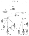
- a CDMA wireless communication system having a plurality of mobile terminals 100, a plurality of base stations (BSs) 270, base station controllers (BSCs) 275, and a mobile switching center (MSC) 280.
- the MSC 280 is configured to interface with a conventional Public Switch Telephone Network (PSTN) 290.
- PSTN Public Switch Telephone Network
- the MSC 280 is also configured to interface with the BSCs 275.
- the BSCs 275 are coupled to the base stations 270 via backhaul lines.
- the backhaul lines may be configured in accordance with any of several known interfaces including, for example, E1/T1, ATM, IP, PPP, Frame Relay, HDSL, ADSL, or xDSL.
- the plurality of BSCs 275 can be included in the system as shown in FIG. 3 .
- Each base station 270 may include one or more sectors, each sector having an omnidirectional antenna or an antenna pointed in a particular direction radially away from the base station 270. Alternatively, each sector may include two or more different antennas. Each base station 270 may be configured to support a plurality of frequency assignments, with each frequency assignment having a particular spectrum (e.g., 1.25 MHz, 5 MHz, etc.).
- the intersection of sector and frequency assignment may be referred to as a CDMA channel.
- the base stations 270 may also be referred to as Base Station Transceiver Subsystems (BTSs).
- BTSs Base Station Transceiver Subsystems
- the term "base station” may be used to refer collectively to a BSC 275, and one or more base stations 270.
- the base stations may also be denoted as "cell sites.” Alternatively, individual sectors of a given base station 270 may be referred to as cell sites.
- a broadcasting transmitter (BT) 295 transmits a broadcast signal to the mobile terminals 100 operating within the system.
- the broadcast receiving module 111 ( FIG. 1 ) is typically configured inside the mobile terminal 100 to receive broadcast signals transmitted by the BT 295.
- FIG. 3 further depicts several Global Positioning System (GPS) satellites 300.
- GPS Global Positioning System
- Such satellites 300 facilitate locating the position of at least one of plural mobile terminals 100.
- Two satellites are depicted in FIG. 4 , but it is understood that useful position information may be obtained with greater or fewer satellites than two satellites.
- the GPS module 115 FIG. 1 ) is typically configured to cooperate with the satellites 300 to obtain desired position information. It is to be appreciated that other types of position detection technology, (i.e., location technology that may be used in addition to or instead of GPS location technology) may alternatively be implemented. If desired, at least one of the GPS satellites 300 may alternatively or additionally be configured to provide satellite DMB transmissions.
- the base stations 270 receive sets of reverse-link signals from various mobile terminals 100.
- the mobile terminals 100 are engaging in calls, messaging, and executing other communications.
- Each reverse-link signal received by a given base station 270 is processed within that base station 270.
- the resulting data is forwarded to an associated BSC 275.
- the BSC 275 provides call resource allocation and mobility management functionality including the orchestration of soft handoffs between base stations 270.
- the BSCs 275 also route the received data to the MSC 280, which then provides additional routing services for interfacing with the PSTN 290.
- the PSTN 290 interfaces with the MSC 280
- the MSC 280 interfaces with the BSCs 275, which in turn control the base stations 270 to transmit sets of forward-link signals to the mobile terminals 100.
- a proximity touch in the present invention may denote that a pointer is positioned close to a screen without actually touching the screen.
- the pointer may include subjects, such as stylus pen, finger or the like, for substantially touching a specific portion on a display screen or proximately touching the portion.
- the controller 180 may control the mobile terminal by recognizing a proximity touch as a specific signal input. That is, the mobile terminal 100 according to the one embodiment of the present invention may be configured such that when a pointer approaches a screen within a range of a predetermined distance, it is recognized as a proximity touch, so as to perform, for example, viewing of various lists and automatic input function (e.g., ID and password).
- the predetermined distance may denote a perpendicular distance between the pointer and the screen.
- a real-touch may denote that a pointer substantially touches a screen.
- the real-touch may be performed by disposing a touch screen on a display.
- the controller 180 may perform a control operation of the mobile terminal by recognizing the real-touch as a specific signal input.
- the mobile terminal 100 may detect the proximity touch and the real-touch by the sensing unit 140.
- the sensing unit 140 may be provided with various sensors for performing different sensing functionalities, and also provided with a proximity sensor, a haptic sensor and the like for detecting the proximity touch and the real-touch.
- the proximity sensor may detect without any mechanical contact by use of an electro-magnetic force or infrared rays whether an object (or subject) approaches a detection surface of a switch or exists near the detection surface.
- the proximity sensor may be configured as a proximity switch, which outputs an ON/OFF signal when a subject to be detected comes within a detection distance defined by each sensor without any mechanical contact, other than outputting the ON/OFF signal responsive to a mechanical contact.
- the proximity sensor configured as the proximity switch may have a lifespan longer than that of a haptic switch and obtain considerably high utilization.
- the proximity sensor configured as the proximity switch may operate such that while an oscillator circuit oscillates a high frequency sine wave, if a subject to be detected moves close to a detection surface of a sensor, an oscillation amplitude of the oscillator circuit is attenuated or stopped, and such change is converted into an electric signal, thereby detecting an existence of the subject to be detected.
- the haptic sensor may denote a sensor for detecting a contact of a specific subject as strong as a person can feel or stronger than that.
- the haptic sensor can detect various information, including how rough a contact surface is, how hard a contact subject is, what the temperature of a contacted portion is, and the like.
- the sensing unit 140 may detect proximity patterns, such as proximity distance and proximity speed, as a detailed operation related to a proximity touch.
- the proximity distance may denote a distance of a pointer being far away from a screen.
- a minimum proximity distance may denote a shortest distance of the pointer being far away from the screen.
- the proximity speed may include a speed of a pointer moving towards a screen or a speed of the pointer moving away from the screen.
- the sensing unit 140 may also detect a touch-drag or a proximity-drag, in relation to a real touch and/or a proximity touch.
- the sensing unit 140 may detect various information related to a dragged direction of the touch-drag and/or proximity-drag, a dragged speed, a dragged distance, and the like.
- the touch-drag indicates that a touched point is dragged in a state that an real touch is maintained
- the proximity-drag indicates that a proximately touched point is dragged in a state that a proximity touch is maintained.
- inputting a proximity touch above a predetermined point of a screen in the embodiments of the present invention may denote that a pointer is located at a position of a space perpendicularly corresponding to the predetermined point and thus the position is recognized as a proximity touch.
- the mobile terminal 100 in accordance with the one embodiment of the present invention can control an information input function by using a proximity touch, and also control a display screen based upon the relation between a real touch and a proximity touch. For instance, the mobile terminal 100 can perform various functions of scrolling a screen, zooming a screen, rotating a screen, displaying information and the like, based upon the relation between the real touch and the proximity touch.
- the proximity touch sensor may detect a proximity touch according to the change in a capacitance generated when a part of body, e.g., a finger, comes in contact with a surface of a touch screen.
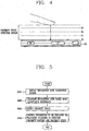
- FIG. 4 is an exemplary view showing that a proximity touch detecting region detected by the proximity sensor is divided into a plurality of proximity positions (or proximity distances). The number of proximity positions shown in FIG. 4 may depend on the performance of the proximity sensor and a target to be controlled, and the present invention exemplarily illustrates four proximity positions D0 to D3.
- the proximity touch may denote that a pointer is positioned at an outer region of each proximity position D0 to D3.
- a mobile terminal may be configured such that the number, positions and types of objects displayed on a display 151 are fixed according to manufacturers and types of devices.
- the present invention controls, in various manners, operations of objects, namely, icons, avatars, menus and the like displayed on the display 151, and their displaying effects on a screen.
- At least one or more icons touched by a pointer for selection may be displayed on the display 151 of the mobile terminal.
- the icons may include an icon for controlling operations of the mobile terminal itself, and an icon for accessing a specific site via the mobile terminal or executing a specific function.
- the pointer may denote one of tools, such as stylus pen, finger or the like, for substantially touching a specific portion on a display screen or inputting a proximity touch on the portion.
- every person (user) does not generate the same capacitance. That is, a difference between a value of a minute change in capacitances generated when a part of human body (e.g., a finger) approaches a touch screen and a set value may occur depending on each person (user).
- a recognition rate may differ for each person, which requires the recognition rate of a proximity sensor to be calibrated so as to be appropriate for each user.
- a proximity calibration screen may be displayed on the display 151 of the mobile terminal.
- the proximity calibration screen may be displayed by separately entering or touching a key within a menu.
- the proximity calibration screen may display a predetermined reference figure (e.g., circle and other polygons) indicating a maximum (the closest) position (minimum height) of a proximity touch and a minimum (the farthest) position (maximum height) of a proximity touch of a pointer, and a guide figure having a size changed in cooperation with the movement of the pointer.
- the pointer may denote one of tools, such as stylus pen, finger or the like, for substantially touching a specific portion on a display screen or inputting a proximity touch on the portion.
- the guide figure may be displayed as a spot upon a real touch of the pointer. Also, the size of the guide figure may be changed to be the same to that of the reference figure upon a proximity touch of the pointer.
- another embodiment may be implemented to calibrate a difference of recognition rates caused by a difference of proximity distances (positions) by means of a subject having a maximum/minimum height evenly controlled.
- the subject may be formed of a material which does not change a capacitance generated upon being contacted by a body.
- FIG. 5 is a flowchart showing a method for controlling a display screen of a mobile terminal using a proximity touch in accordance with an embodiment of the present invention.
- the controller 180 displays a screen for calibrating the recognition rate of a proximity touch on the display 151 (S100).
- the proximity calibration screen may display a predetermined reference figure (e.g., circle and other polygons) indicating a maximum (the closest) position (minimum height) of a proximity touch and a minimum (the farthest) position (maximum height) of a proximity touch of a pointer, and a guide figure having a size changed in cooperation with the movement of the pointer.
- the guide figure may be displayed as a spot upon a real touch of the pointer. Also, the size of the guide figure may be changed to be the same to that of the reference figure upon a proximity touch of the pointer.
- the controller 180 displays on the screen one guide circle indicating a current proximity position and a reference circle indicating a maximum proximity position. Afterwards, as the finger moves closer to the screen or farther away from the screen, the size of the guide circle is decreased or increased, thereby calibrating a recognition rate caused due to a difference of capacitances (S200).
- the controller 180 controls in various manners operations of objects, namely, icons, avatars, menus and the like displayed on an idle screen and their displaying effects on the screen according to detected proximity position and proximity speed.
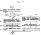
- FIG. 6 is a flowchart showing a method for calibrating a recognition rate of a proximity touch in the mobile terminal according to the embodiment of the present invention.
- the controller 180 may display a screen for calibrating a recognition rate of a proximity touch according to a user's touch input (or a separate key input) (S10). If any touch input is detected in the state of the screen being displayed, the controller 180 determines whether or not the corresponding touch is a real touch (S11).
- the controller 180 displays a touched point (or a guide circle if a finger is apart from the screen) and a predetermined reference figure, e.g., a first reference circle, which indicates a minimum proximity position (S12).
- the minimum proximity position corresponds to D3 located at the outermost side in FIG. 4 , and the touched point is changed into the guide circle when the finger is apart from the screen.
- the guide circle is gradually larger in size to have the same size to that of the first reference circle.
- the size of the guide circle becomes larger in cooperation with proximity positions (or proximity distances) being farther (S13).
- the pointer may be one of subjects, such as stylus pen, finger or the like, for substantially touching a specific portion on a display screen or inputting a proximity touch on the portion.
- a capacitance at the corresponding position is set to a capacitance at a minimum proximity position, thereby calibrating a minimum value of the proximity touch (S14).
- Step S11 upon a proximity touch being detected, the controller 180 displays on a screen a guide circle indicating a proximity position and a predetermined reference figure, e.g., a second reference circle, indicating a maximum proximity position (S15).
- the maximum proximity touch corresponds to D0 positioned at the innermost position in FIG. 4 .
- FIG. 7 is a flowchart showing in detail a method for setting a minimum value of a proximity touch of FIG. 6 .
- the controller 180 displays a screen for calibrating a recognition rate of a proximity touch according to a user's touch (or a separate key input).
- the controller 180 When a finger touches the screen of the touch screen, the controller 180 displays the corresponding touch point and one reference circle indicating a minimum proximity position (S20 and S21).
- the controller 180 compares whether the size of the guide circle is the same to the size of the reference circle (S24). If the sizes are the same to each other according to the comparison result, the controller 180 recognizes it as the finger arrives at the minimum proximity position, and then calibrates a capacitance at the corresponding position with the minimum value of the proximity touch (S25).
- FIG. 8 is an exemplary view of performing the method shown in FIG. 7 .
- the controller 180 displays a touch point 50 and one reference circle 51 indicating a minimum proximity position.
- the touch point 50 is changed into a guide circle 52.
- the size of the guide circle 52 is increased or decreased in cooperation with the proximity position (or proximity distance) being farther or closer.
- the controller 180 recognizes it as the finger arrives at the minimum proximity position, and calibrates the capacitance at the corresponding position with the minimum value of the proximity touch.
- the recognition rate due to the difference of capacitances can be calibrated and increased, which allows a user to use the more accurate proximity touch function.
- FIG. 9 is a flowchart showing in detail the method for setting the minimum value of a proximity touch of FIG. 6 .
- the controller 180 can display a screen for calibrating a recognition rate of a proximity touch according to a user's touch (or a separate key input). Also, the operations of FIG. 9 may consecutively be performed in related to the operations of FIG. 7 .
- the controller 180 displays on the screen one guide circle indicating a current proximity touch and a reference circle indicating a maximum proximity position (S30 and S31). The maximum proximity position corresponds to D0 located at the innermost side in FIG. 4 .
- the size of the guide circle is cooperatively decreased as the proximity position (or proximity distance) is getting closer to the screen (S32 and S33).
- the controller 180 compares whether the size of the guide circle is the same to the size of the reference circle (S34). If the sizes are the same to each other according to the comparison result, the controller 180 recognizes it as the finger arrives at the maximum proximity position D0, and thus calibrates the capacitance at the corresponding position with the maximum value of the proximity touch S(35).
- FIG. 10 is an exemplary view of performing the method shown in FIG. 9 .
- the controller 180 In a state where the minimum value of the proximity touch has been calibrated or if a finger inputs a proximity touch on the recognition rate calibration screen, the controller 180 displays a guide circle 52 indicating a proximity position and a reference circle 53 indicating a maximum proximity position.
- the controller 180 recognizes it as the finger arrives at the maximum proximity position, and thus calibrates the capacitance at the corresponding position with the maximum value of the proximity touch.
- the recognition rate due to the difference of capacitances can be calibrated and increased, which allows a user to use the more accurate proximity touch function.
- the embodiment of the present invention may be implemented such that the operations of FIG. 7 are first performed and the operations of FIG. 9 are then performed.
- it may be implemented such that the operations of FIG. 9 are first performed and the operations of FIG. 7 are then performed. That is, when a real touch is first performed on the recognition rate calibration screen, the operations may be executed in the order of FIG. 7 ⁇ FIG. 9 .
- the operations may be executed in the order of FIG. 9 ⁇ FIG. 7 .
- a reference circle and a guide circle represented on the screen are defined.
- the arrival to the minimum proximity position or maximum proximity position was performed by comparing the reference circle with the guide circle, and thereafter the minimum value and the maximum value of the proximity touch were set (or calibrated) at the corresponding positions.
- the present invention may not be limited to such embodiment; however, every user may be allowed to have the same minimum proximity position or maximum proximity position so as to set (or calibrate) the minimum value and the maximum value of the proximity touch at the corresponding positions.
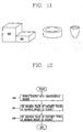
- the subject as a non-conductor with a maximum height and a minimum height, as shown in FIG. 11 may be formed of a material (e.g., non-conducting substance, rubber and the like) in a shape (e.g. an annular shape), thereby not affecting the measurement of the capacitance of the finger.
- FIG. 12 is a flowchart showing a method for calibrating a proximity touch recognition rate using a subject with a maximum height and a minimum height in accordance with an embodiment useful for understanding the present invention
- FIG. 13 is an exemplary view of performing the method shown in FIG. 12 .
- a user places on a touch screen a subject 54 with a maximum height and a minimum height in a mode for calibrating a recognition rate of a proximity touch.
- the controller 180 detects the position of the subject 54.
- the controller 180 sets a capacitance of a finger which touches the subject 54 at the maximum height to a minimum value of the proximity touch (S40 and S41), and sets a capacitance of the finger which touches the subject 54 at the minimum height to a maximum value of the proximity touch (S42).
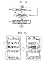
- FIG. 14 is a flowchart showing a screen displaying method using a proximity touch in a mobile terminal according to an embodiment of the present invention, which particularly shows a method for controlling a display screen according to a proximity position and a proximity speed.
- An idle screen of the mobile terminal displays at least one or more avatars by which various operations of the mobile terminal can immediately be executed without selecting a menu.
- the avatars may be set to have the same size, and their positions and arrangement may optionally be changed by a user.
- the sensing unit 140 detects the proximity touch of the pointer, thereby to calculate a proximity position (distance) and/or a proximity speed based upon the detected data (S50).
- the pointer include subjects, such as stylus pen, finger or the like, for substantially touching a specific portion on a display screen or inputting a proximity touch on the portion.
- the controller 180 receives the proximity position and the proximity speed from the sensing unit 140, and controls displaying of information on the standby screen, e.g., controls at least one or more of sizes, positions and movements of the avatars, according to the proximity position and the proximity speed of the pointer (S51 and S52).
- the present invention may set the proximity position (distance) to D2 of FIG. 4 , for example.
- FIG. 15 is an exemplary view of the method shown in FIG. 14 .
- FIG. 15 shows that a size of an icon is changed according to a proximity position (distance) of a pointer (a finger in this example).
- the sensing unit 140 detects a proximity position of the finger and outputs the detected proximity position to the controller 180.
- the controller 180 controls the size of the corresponding icon to be larger than other icons so as to be easily selected.
- the sizes of the icons may be controlled such that an icon to be selected can have a large size and others become smaller about a proximity touch point.
- the avatars on the standby screen may be returned to their original positions and sizes.
- the user can substantially touch the size-increased icon to perform his desired operation.
- FIG. 16 is another exemplary view of performing the method shown in FIG. 14 .
- FIG. 16 shows that size and position of an icon are changed according to a proximity position (distance) of a finger. That is, when a user places his finger above an icon desiring to select, other icons become smaller and distributed around the selected icon. The selected icon becomes larger at its original position.
- the icon to be selected may become larger in size and other icons are gradually getting smaller in sizes to be distributed from a central portion of the screen towards the outer sides thereof, according to the proximity distance of the finger.
- the sizes of the icons and the speed of the icons being distributed may be controlled according to a proximity speed.
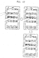
- FIG. 17 is another exemplary view of performing the method shown in FIG. 14 .
- FIG. 17 shows that an effect is applied to an icon according to a proximity position (distance) of a finger.
- the controller 180 can control the icon to be selected or its neighboring icons to be rotated at their positions. If only the icon to be selected is rotated, the rotation speed may differ according to the proximity position. Further, if the icon to be selected or its neighboring icons are rotated, the icon to be selected may be rotated at a high speed and the neighboring icons may be rotated at a lower speed.
- the controller 180 controls the alarm 153 of the output unit 150 so as to apply a vibration (effect) to the icon to be selected.
- the strength of the vibration may be controlled according to the proximity position (distance) or the proximity speed of the finger. For instance, if the finger fast approaches the icon to be selected, the strength of the vibration may be increased or become rough. On the other hand, if the finger slowly moves toward the icon to be selected, the strength of the vibration may become weaker or softer.
- the present invention may be configured such that when a finger moves close to a specific icon, the audio output module 152 of the output unit 150 may be controlled to output sound.
- FIG. 18 is another exemplary view of the method shown in FIG. 14 .
- FIG. 18 shows a method for controlling positions and movements of subjects on a wallpaper (background screen, idle screen, standby screen) according to a proximity position and a proximity speed.
- a wallpaper background screen, idle screen, standby screen
- users may often set a wallpaper to a form of an animation or idle screen including subjects such as fishes or animals.
- the controller 180 may control the positions and movements of the subjects based upon proximity position (distance) and proximity speed detected by the sensing unit 140.
- the controller 180 may control the wallpaper such that the fishes or animals gather around the finger or run away from the finger when the finger comes close to the screen.
- the controller 180 may control the wallpaper such that the fishes or animals gather around the finger or run away from the finger when the finger comes close to the screen.
- a speed of fishes being gathered or run away may be differently set according to a proximity speed of the finger.
- the fishes may be fast run away from the position where the finger approaches and be kept away from the position. Even in this case, the strength of vibration and the effect (or effect sound) may differently be controlled in cooperation with the movement of the objects (e.g., animals, fishes and the like).
- the wallpaper may be returned to its original state.
- the controller 180 may display a menu or icon hidden in a specific position when a user moves a pointer towards the corresponding position.
- the menu or icon may be changed according to a distance of the pointer being close to the screen. Generally, as the pointer comes closer, a larger portion of the menu or icon may be viewable. Also, the menu or icon may be set to make a different strength of vibration or a different effect (effect sound) according to the proximity speed of the pointer.
- a user may be allowed to conveniently select his desired menu or avatar. However, if too many menus or avatars are displayed, they may spoil the screen. Thus, some ofmenus or avatars may be displayed if necessary.
- the controller 180 checks a position of the wallpaper where the proximity touch is generated. Upon checking the position where the proximity touch is generated, the controller 180 displays menus or avatars hidden in the corresponding position on the wallpaper.
- the speed displaying the menus or avatars may be in proportion to the proximity speed.
- the sizes or movements of the menus or avatars can be controlled or the generation of vibration or output sound can be controlled.
- FIG. 19 is a view showing an embodiment of performing the method shown in FIG. 14 , which shows one embodiment of displaying menus or icons hidden in a specific position.
- a size or movement of a menu or avatar to be selected may be controlled or a generation of vibration or output sound may be controlled.
- the wallpaper may be returned to its original state.
- the operation of controlling the operating method e.g., controlling size, movement, and effect
- a proximity position e.g., controlling size, movement, and effect
- a proximity speed on the wallpaper e.g., controlling speed, speed, and speed on the wallpaper
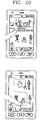
- FIG. 20 shows an embodiment of performing the method shown in FIG. 14 , which exemplarily shows that contents included in a corresponding icon is displayed on a screen or characters displayed on the screen are moved along a touch being moved. That is, the proximity touch may be used to perform, for example, displaying profile information relating to a friend, using a messenger, placing a call, sending SMS MMS or e-mail, and the like.
- the aforesaid methods according to one embodiment of the present invention can be implemented as computer-readable codes in a program-recorded medium.
- the computer-readable medium may include all types of recording devices each storing data readable by a computer system.
- Examples of such computer-readable media may include ROM, RAM, CD-ROM, magnetic tape, floppy disk, optical data storage element and the like. Also, the computer-readable medium may also be implemented as a format of carrier wave (e.g., transmission via an Internet).
- the computer may include the controller 180 of the mobile terminal.
Landscapes
- Engineering & Computer Science (AREA)
- General Engineering & Computer Science (AREA)
- Theoretical Computer Science (AREA)
- Human Computer Interaction (AREA)
- Physics & Mathematics (AREA)
- General Physics & Mathematics (AREA)
- Telephone Function (AREA)
- User Interface Of Digital Computer (AREA)
Claims (4)
- Terminal mobile (100) comprenant :un afficheur (151) pour afficher une pluralité d'objets sur un écran tactile,une unité de détection (140) conçue pour détecter un contact tactile réel sur un point de contact sur la surface de l'écran tactile et un contact tactile de proximité d'un pointeur, etcaractérisé en ce qu'il comprend en outre un organe de commande (180) conçu pour :afficher un écran pour étalonner un taux de reconnaissance du contact tactile de proximité ;détecter (S20) un contact tactile réel du pointeur sur l'écran tactile ;afficher (S21) un point tactile (50) correspondant au contact tactile réel et un cercle de référence (51) indiquant une position de proximité minimum, ladite position de proximité minimum correspondant à une hauteur maximum d'un contact tactile de proximité d'un pointeur ;si le pointeur s'éloigne de l'écran tactile, modifier le point tactile (50) vers un cercle de guidage (52) ;augmenter (S23) ou réduire la taille du cercle de guidage (52) selon une augmentation ou une réduction de la distance entre le pointeur et l'écran tactile ;comparer (S24) la taille du cercle de guidage (52) et la taille du cercle de référence (51) ;si les tailles du cercle de guidage (52) et du cercle de référence (51) sont identiques, le reconnaître en tant que position de proximité minium et définir (S25) une valeur de capacitance de l'unité de détection (410) correspondant à la position de proximité minimum comme une valeur de capacitance minium.
- Terminal selon la revendication 1, le pointeur comprenant un stylet ou un doigt.
- Terminal selon la revendication 1, les objets comprenant des icônes, des avatars et des menus, et l'écran étant un papier peint conçu sous la forme d'animation ou de flash, et des opérations relatives aux objets consistant à régler les tailles, les vitesses de déplacement, les mouvements, les vibrations et les effets sonores des objets.
- Terminal selon la revendication 1, l'organe de commande (180) étant conçu pour amener les objets à être affichés différemment selon la position de proximité et la vitesse de proximité, et pour afficher un objet caché dans une position correspondante lorsque le pointeur s'approche d'une région prédéfinie de l'écran.
Applications Claiming Priority (2)
| Application Number | Priority Date | Filing Date | Title |
|---|---|---|---|
| KR1020080046743A KR101537684B1 (ko) | 2008-05-20 | 2008-05-20 | 이동 단말기 및 그 이동 단말기를 위한 근접 터치의 인식률교정방법 |
| KR1020080047125A KR101502002B1 (ko) | 2008-05-21 | 2008-05-21 | 근접 터치를 이용한 이동 단말기 및 그의 화면표시제어방법 |
Publications (3)
| Publication Number | Publication Date |
|---|---|
| EP2124138A2 EP2124138A2 (fr) | 2009-11-25 |
| EP2124138A3 EP2124138A3 (fr) | 2014-12-24 |
| EP2124138B1 true EP2124138B1 (fr) | 2019-09-11 |
Family
ID=40875069
Family Applications (1)
| Application Number | Title | Priority Date | Filing Date |
|---|---|---|---|
| EP09006851.1A Active EP2124138B1 (fr) | 2008-05-20 | 2009-05-20 | Terminal mobile utilisant un détecteur de proximité |
Country Status (2)
| Country | Link |
|---|---|
| US (1) | US8576181B2 (fr) |
| EP (1) | EP2124138B1 (fr) |
Families Citing this family (128)
| Publication number | Priority date | Publication date | Assignee | Title |
|---|---|---|---|---|
| US20070287541A1 (en) * | 2001-09-28 | 2007-12-13 | Jeffrey George | Tracking display with proximity button activation |
| US8381135B2 (en) | 2004-07-30 | 2013-02-19 | Apple Inc. | Proximity detector in handheld device |
| US8284165B2 (en) | 2006-10-13 | 2012-10-09 | Sony Corporation | Information display apparatus with proximity detection performance and information display method using the same |
| EP2104024B1 (fr) * | 2008-03-20 | 2018-05-02 | LG Electronics Inc. | Terminal portable capable de détecter un toucher de proximité et procédé pour écran de contrôle l'utilisant |
| US9030418B2 (en) * | 2008-06-24 | 2015-05-12 | Lg Electronics Inc. | Mobile terminal capable of sensing proximity touch |
| KR20100031204A (ko) * | 2008-09-12 | 2010-03-22 | 삼성전자주식회사 | 근접 센서 기반의 입력 장치 및 그의 운용 방법 |
| JP4775669B2 (ja) * | 2008-10-10 | 2011-09-21 | ソニー株式会社 | 情報処理装置、情報処理方法、情報処理システムおよび情報処理用プログラム |
| KR101554183B1 (ko) * | 2008-10-15 | 2015-09-18 | 엘지전자 주식회사 | 이동 단말기 및 그의 출력 제어 방법 |
| US9740341B1 (en) | 2009-02-26 | 2017-08-22 | Amazon Technologies, Inc. | Capacitive sensing with interpolating force-sensitive resistor array |
| US10180746B1 (en) | 2009-02-26 | 2019-01-15 | Amazon Technologies, Inc. | Hardware enabled interpolating sensor and display |
| KR101582686B1 (ko) * | 2009-03-02 | 2016-01-05 | 엘지전자 주식회사 | 아이템 표시 방법 및 이를 적용한 이동 통신 단말기 |
| JP5158014B2 (ja) * | 2009-05-21 | 2013-03-06 | ソニー株式会社 | 表示制御装置、表示制御方法およびコンピュータプログラム |
| JP5563250B2 (ja) * | 2009-06-30 | 2014-07-30 | 株式会社ジャパンディスプレイ | 立体画像表示装置 |
| US9323398B2 (en) | 2009-07-10 | 2016-04-26 | Apple Inc. | Touch and hover sensing |
| US9244562B1 (en) | 2009-07-31 | 2016-01-26 | Amazon Technologies, Inc. | Gestures and touches on force-sensitive input devices |
| US9785272B1 (en) | 2009-07-31 | 2017-10-10 | Amazon Technologies, Inc. | Touch distinction |
| JP5471137B2 (ja) * | 2009-08-05 | 2014-04-16 | ソニー株式会社 | 表示装置、表示方法及びプログラム |
| US20110057886A1 (en) * | 2009-09-10 | 2011-03-10 | Oliver Ng | Dynamic sizing of identifier on a touch-sensitive display |
| JP2011086179A (ja) * | 2009-10-16 | 2011-04-28 | Sony Corp | 情報入力装置、情報入力方法、情報入出力装置、情報入力プログラムおよび電子機器 |
| KR20110051044A (ko) * | 2009-11-09 | 2011-05-17 | 광주과학기술원 | 사용자에게 3차원 객체의 촉감 정보를 제공하는 방법 및 장치 |
| CA2780765A1 (fr) * | 2009-11-13 | 2011-05-19 | Google Inc. | Papier peint dynamique |
| US8810524B1 (en) | 2009-11-20 | 2014-08-19 | Amazon Technologies, Inc. | Two-sided touch sensor |
| KR20110067559A (ko) * | 2009-12-14 | 2011-06-22 | 삼성전자주식회사 | 디스플레이장치 및 그 제어방법, 디스플레이시스템 및 그 제어방법 |
| JP2011134272A (ja) * | 2009-12-25 | 2011-07-07 | Sony Corp | 情報処理装置、情報処理方法およびプログラム |
| JP5526789B2 (ja) * | 2010-01-08 | 2014-06-18 | ソニー株式会社 | 情報処理装置およびプログラム |
| TWI408592B (zh) * | 2010-02-02 | 2013-09-11 | Hon Hai Prec Ind Co Ltd | 觸控板以及使用該觸控板的電子裝置 |
| JP5716009B2 (ja) * | 2010-03-05 | 2015-05-13 | レノボ・イノベーションズ・リミテッド(香港) | 携帯端末装置 |
| JP5545009B2 (ja) * | 2010-04-28 | 2014-07-09 | ソニー株式会社 | センサ装置および情報表示装置 |
| US8780059B2 (en) | 2010-05-28 | 2014-07-15 | Nokia Corporation | User interface |
| JP5573379B2 (ja) * | 2010-06-07 | 2014-08-20 | ソニー株式会社 | 情報表示装置および表示画像制御方法 |
| US9851829B2 (en) * | 2010-08-27 | 2017-12-26 | Apple Inc. | Signal processing for touch and hover sensing display device |
| JP5617603B2 (ja) * | 2010-12-21 | 2014-11-05 | ソニー株式会社 | 表示制御装置、表示制御方法、及び、プログラム |
| JP5652652B2 (ja) * | 2010-12-27 | 2015-01-14 | ソニー株式会社 | 表示制御装置および方法 |
| KR20120084860A (ko) * | 2011-01-21 | 2012-07-31 | 삼성전자주식회사 | 정전식 터치스크린 단말기에서 입력 방법 및 장치 |
| FR2971066B1 (fr) | 2011-01-31 | 2013-08-23 | Nanotec Solution | Interface homme-machine tridimensionnelle. |
| JP5810554B2 (ja) * | 2011-02-28 | 2015-11-11 | ソニー株式会社 | 電子装置、表示方法、およびプログラム |
| JP5708083B2 (ja) * | 2011-03-17 | 2015-04-30 | ソニー株式会社 | 電子機器、情報処理方法、プログラム、及び電子機器システム |
| KR101781908B1 (ko) * | 2011-03-24 | 2017-09-26 | 엘지전자 주식회사 | 이동 단말기 및 그것의 제어방법 |
| US20140111430A1 (en) * | 2011-06-10 | 2014-04-24 | Nec Casio Mobile Communications, Ltd. | Input device and control method of touch panel |
| CN102830862A (zh) * | 2011-06-15 | 2012-12-19 | 比亚迪股份有限公司 | 用于电容触摸屏的定位方法及定位装置、触控系统 |
| EP2541383B1 (fr) * | 2011-06-29 | 2021-09-22 | Sony Group Corporation | Dispositif et procédé de communications |
| EP2730998B1 (fr) * | 2011-07-04 | 2018-05-02 | NEC Corporation | Dispositif de traitement d'images, procédé de traitement d'images, et programme de traitement d'images |
| CN102890611B (zh) | 2011-07-21 | 2016-03-30 | 华为技术有限公司 | 一种基于触摸式操作提供文件夹项目信息的方法及装置 |
| US9569066B2 (en) * | 2011-10-03 | 2017-02-14 | Google Inc. | Interface for navigating imagery |
| US8836654B2 (en) * | 2011-10-04 | 2014-09-16 | Qualcomm Incorporated | Application window position and size control in (multi-fold) multi-display devices |
| KR101892266B1 (ko) * | 2011-10-06 | 2018-08-28 | 삼성전자주식회사 | 입력 판단 방법 및 그 장치 |
| US9195349B2 (en) * | 2011-10-20 | 2015-11-24 | Nokia Technologies Oy | Apparatus, method and computer program using a proximity detector |
| US8872794B2 (en) | 2011-10-28 | 2014-10-28 | Sony Corporation | Information processing apparatus |
| US20130125066A1 (en) * | 2011-11-14 | 2013-05-16 | Microsoft Corporation | Adaptive Area Cursor |
| JP2013125247A (ja) * | 2011-12-16 | 2013-06-24 | Sony Corp | ヘッドマウントディスプレイ及び情報表示装置 |
| US9030407B2 (en) | 2011-12-21 | 2015-05-12 | Nokia Technologies Oy | User gesture recognition |
| US20140062946A1 (en) * | 2011-12-29 | 2014-03-06 | David L. Graumann | Systems and methods for enhanced display images |
| US9116598B1 (en) | 2012-01-10 | 2015-08-25 | Koji Yoden | User interface for use in computing device with sensitive display |
| KR101991493B1 (ko) * | 2012-01-17 | 2019-06-20 | 삼성전자주식회사 | 터치 인터페이스를 제공하는 방법, 기계로 읽을 수 있는 저장 매체 및 휴대 단말 |
| US9037683B1 (en) | 2012-03-05 | 2015-05-19 | Koji Yoden | Media asset streaming over network to devices |
| EP2645218A1 (fr) * | 2012-03-29 | 2013-10-02 | Sony Mobile Communications AB | Procédé de fonctionnement d'un dispositif électronique |
| US9201547B2 (en) | 2012-04-30 | 2015-12-01 | Apple Inc. | Wide dynamic range capacitive sensing |
| AU2013205613B2 (en) * | 2012-05-04 | 2017-12-21 | Samsung Electronics Co., Ltd. | Terminal and method for controlling the same based on spatial interaction |
| JP5579780B2 (ja) * | 2012-06-06 | 2014-08-27 | パナソニック インテレクチュアル プロパティ コーポレーション オブ アメリカ | 入力装置、入力支援方法及びプログラム |
| KR101986218B1 (ko) * | 2012-08-02 | 2019-06-05 | 삼성전자주식회사 | 디스플레이 장치 및 방법 |
| KR101913817B1 (ko) * | 2012-08-29 | 2018-10-31 | 삼성전자주식회사 | 터치스크린 입력 처리 방법 및 장치 |
| KR20140066378A (ko) * | 2012-11-23 | 2014-06-02 | 삼성전자주식회사 | 디스플레이장치와 그 제어방법 |
| US9075514B1 (en) * | 2012-12-13 | 2015-07-07 | Amazon Technologies, Inc. | Interface selection element display |
| US9323353B1 (en) * | 2013-01-15 | 2016-04-26 | American Megatrends, Inc. | Capacitance sensing device for detecting a three-dimensional location of an object |
| DE202013000751U1 (de) * | 2013-01-25 | 2013-02-14 | Volkswagen Aktiengesellschaft | Vorrichtung zum Anzeigen einer Vielzahl von flächigen Objekten |
| WO2014125857A1 (fr) * | 2013-02-13 | 2014-08-21 | Necカシオモバイルコミュニケーションズ株式会社 | Dispositif d'entrée et son procédé de commande, et programme |
| FR3002052B1 (fr) * | 2013-02-14 | 2016-12-09 | Fogale Nanotech | Procede et dispositif pour naviguer dans un ecran d'affichage et appareil comprenant une telle navigation |
| US10394434B2 (en) | 2013-02-22 | 2019-08-27 | Samsung Electronics Co., Ltd. | Apparatus and method for recognizing proximity motion using sensors |
| US10261612B2 (en) | 2013-02-22 | 2019-04-16 | Samsung Electronics Co., Ltd. | Apparatus and method for recognizing proximity motion using sensors |
| CN104035699A (zh) * | 2013-03-05 | 2014-09-10 | 中兴通讯股份有限公司 | 电容式触摸屏终端及其输入方法 |
| JP5984722B2 (ja) * | 2013-03-22 | 2016-09-06 | シャープ株式会社 | 情報処理装置 |
| US10319345B2 (en) * | 2013-05-02 | 2019-06-11 | Samsung Electronics Co., Ltd | Portable terminal and method for partially obfuscating an object displayed thereon |
| JP2014219938A (ja) * | 2013-05-10 | 2014-11-20 | 株式会社ゲッシュ | 入力支援装置、入力支援方法、および、プログラム |
| US10089786B2 (en) * | 2013-08-19 | 2018-10-02 | Qualcomm Incorporated | Automatic customization of graphical user interface for optical see-through head mounted display with user interaction tracking |
| US9696882B2 (en) * | 2013-08-28 | 2017-07-04 | Lenovo (Beijing) Co., Ltd. | Operation processing method, operation processing device, and control method |
| KR101386248B1 (ko) * | 2013-09-09 | 2014-04-17 | 재단법인 실감교류인체감응솔루션연구단 | 공간 제스처 인식 장치 및 방법 |
| US10528185B2 (en) | 2013-09-23 | 2020-01-07 | Touchplus Information Corp. | Floating touch method and touch device |
| US20150084921A1 (en) * | 2013-09-23 | 2015-03-26 | Touchplus Information Corp. | Floating touch method and touch device |
| US9689810B2 (en) * | 2013-10-08 | 2017-06-27 | Htc Corporation | Electronic apparatus with proximity sensor and automatic calibration method thereof |
| US20150109257A1 (en) * | 2013-10-23 | 2015-04-23 | Lumi Stream Inc. | Pre-touch pointer for control and data entry in touch-screen devices |
| US9933879B2 (en) | 2013-11-25 | 2018-04-03 | Apple Inc. | Reconfigurable circuit topology for both self-capacitance and mutual capacitance sensing |
| KR102176575B1 (ko) * | 2013-12-30 | 2020-11-09 | 삼성전자주식회사 | 입력을 감지하는 전자 장치 및 방법 |
| KR102186393B1 (ko) * | 2014-01-02 | 2020-12-03 | 삼성전자주식회사 | 입력 처리 방법 및 그 전자 장치 |
| USD765718S1 (en) * | 2014-01-17 | 2016-09-06 | Beats Music, Llc | Display screen or portion thereof with animated graphical user interface |
| KR102166833B1 (ko) * | 2014-01-28 | 2020-10-16 | 엘지전자 주식회사 | 이동단말기 및 그 제어방법 |
| US20150231491A1 (en) * | 2014-02-19 | 2015-08-20 | Microsoft Corporation | Advanced Game Mechanics On Hover-Sensitive Devices |
| US9652044B2 (en) * | 2014-03-04 | 2017-05-16 | Microsoft Technology Licensing, Llc | Proximity sensor-based interactions |
| EP2960763A1 (fr) * | 2014-06-24 | 2015-12-30 | Google, Inc. | Systèmes et procédés informatisés de montage en cascade des animations d'élément d'interface utilisateur |
| JP6381989B2 (ja) * | 2014-06-26 | 2018-08-29 | 京セラ株式会社 | 携帯電子機器、携帯電子機器の制御方法およびプログラム |
| KR20160014481A (ko) * | 2014-07-29 | 2016-02-11 | 삼성전자주식회사 | Idle 모드에서 동작하는 전자 장치 및 방법 |
| EP2998840B1 (fr) * | 2014-09-19 | 2023-08-30 | Kabushiki Kaisha Tokai Rika Denki Seisakusho | Dispositif à capteur tactile capacitif et contrôleur |
| US10042445B1 (en) * | 2014-09-24 | 2018-08-07 | Amazon Technologies, Inc. | Adaptive display of user interface elements based on proximity sensing |
| KR102399589B1 (ko) * | 2014-11-05 | 2022-05-18 | 삼성전자주식회사 | 디바이스에 오브젝트를 디스플레이 하는 방법, 그 디바이스 및 기록매체 |
| KR20160063812A (ko) | 2014-11-27 | 2016-06-07 | 삼성전자주식회사 | 화면 구성 방법, 전자 장치 및 저장 매체 |
| WO2017019530A1 (fr) * | 2015-07-24 | 2017-02-02 | Silver Curve Games, Inc. | Jeu de rythme de réalité augmentée |
| US10325134B2 (en) | 2015-11-13 | 2019-06-18 | Fingerprint Cards Ab | Method and system for calibration of an optical fingerprint sensing device |
| US20170140233A1 (en) | 2015-11-13 | 2017-05-18 | Fingerprint Cards Ab | Method and system for calibration of a fingerprint sensing device |
| US9990078B2 (en) * | 2015-12-11 | 2018-06-05 | Immersion Corporation | Systems and methods for position-based haptic effects |
| EP3399388A4 (fr) * | 2015-12-30 | 2019-09-04 | Shenzhen Royole Technologies Co. Ltd. | Appareil d'affichage à réalité virtuelle, système d'affichage à réalité virtuelle, et procédé d'entrée |
| US10852913B2 (en) * | 2016-06-21 | 2020-12-01 | Samsung Electronics Co., Ltd. | Remote hover touch system and method |
| US10732759B2 (en) | 2016-06-30 | 2020-08-04 | Microsoft Technology Licensing, Llc | Pre-touch sensing for mobile interaction |
| USD821440S1 (en) | 2016-07-22 | 2018-06-26 | Xiaofeng Li | Display screen with transitional graphical user interface for controlling an electronic candle |
| USD824936S1 (en) | 2016-07-22 | 2018-08-07 | Xiaofeng Li | Display screen with graphical user interface for operating an electronic candle |
| USD853417S1 (en) | 2016-07-11 | 2019-07-09 | Xiaofeng Li | Display screen with graphical user interface for operating an electronic candle |
| US10318034B1 (en) * | 2016-09-23 | 2019-06-11 | Apple Inc. | Devices, methods, and user interfaces for interacting with user interface objects via proximity-based and contact-based inputs |
| CN106648329A (zh) * | 2016-12-30 | 2017-05-10 | 维沃移动通信有限公司 | 一种应用图标的显示方法及移动终端 |
| US20180239509A1 (en) * | 2017-02-20 | 2018-08-23 | Microsoft Technology Licensing, Llc | Pre-interaction context associated with gesture and touch interactions |
| US10254846B1 (en) * | 2017-03-15 | 2019-04-09 | Meta Company | Systems and methods to facilitate interactions with virtual content in an augmented reality environment |
| CN107290802B (zh) * | 2017-07-18 | 2019-03-01 | Oppo广东移动通信有限公司 | 接近传感器校准方法、接近传感器校准装置及智能终端 |
| CN108279846A (zh) * | 2018-01-31 | 2018-07-13 | 北京硬壳科技有限公司 | 一种手势模型建立、手势认证的方法及装置 |
| WO2019163503A1 (fr) * | 2018-02-22 | 2019-08-29 | 京セラ株式会社 | Dispositif électronique, procédé de commande et programme |
| CN111752337B (zh) * | 2019-03-26 | 2022-02-18 | 技嘉科技股份有限公司 | 电子装置 |
| US11209937B2 (en) | 2019-07-08 | 2021-12-28 | Samsung Electronics Co., Ltd. | Error correction for seamless transition between hover and touch sensing |
| WO2022025611A1 (fr) * | 2020-07-28 | 2022-02-03 | 삼성전자 주식회사 | Procédé de configuration d'écran d'accueil et dispositif électronique l'utilisant |
| KR20230124082A (ko) | 2020-12-31 | 2023-08-24 | 스냅 인코포레이티드 | 햅틱 피드백 증강들을 갖는 미디어 콘텐츠 아이템들 |
| US11531400B2 (en) | 2020-12-31 | 2022-12-20 | Snap Inc. | Electronic communication interface with haptic feedback response |
| CN116670635B (zh) | 2020-12-31 | 2026-01-16 | 斯纳普公司 | 具有触觉反馈的实时视频通信界面 |
| EP4272062A1 (fr) | 2020-12-31 | 2023-11-08 | Snap Inc. | Interface de communication avec réponse de rétroaction haptique |
| CN116745743A (zh) | 2020-12-31 | 2023-09-12 | 斯纳普公司 | 具有触觉反馈响应的通信界面 |
| CN112882779B (zh) * | 2021-02-04 | 2025-10-10 | 北京小米移动软件有限公司 | 锁屏显示控制方法、装置、移动终端及存储介质 |
| US12164689B2 (en) | 2021-03-31 | 2024-12-10 | Snap Inc. | Virtual reality communication interface with haptic feedback response |
| US12314472B2 (en) | 2021-03-31 | 2025-05-27 | Snap Inc. | Real-time communication interface with haptic and audio feedback response |
| KR20250164860A (ko) * | 2021-03-31 | 2025-11-25 | 스냅 인코포레이티드 | 햅틱 피드백 응답을 갖는 가상 현실 인터페이스 |
| US12050729B2 (en) | 2021-03-31 | 2024-07-30 | Snap Inc. | Real-time communication interface with haptic and audio feedback response |
| JP7666779B2 (ja) * | 2021-10-14 | 2025-04-22 | アルプスアルパイン株式会社 | 入力装置 |
| JP2023104568A (ja) * | 2022-01-18 | 2023-07-28 | 富士フイルムビジネスイノベーション株式会社 | 情報処理装置及び情報処理プログラム |
| KR20240031501A (ko) * | 2022-08-30 | 2024-03-08 | 삼성디스플레이 주식회사 | 입력 센싱부 및 그것의 구동 방법 |
| JP7421709B1 (ja) | 2023-09-26 | 2024-01-25 | チームラボ株式会社 | キャリブレーション機能付きのシステム、プログラム、及びキャリブレーション方法 |
Family Cites Families (9)
| Publication number | Priority date | Publication date | Assignee | Title |
|---|---|---|---|---|
| US5410488A (en) * | 1992-11-02 | 1995-04-25 | Lorton Aerospace Company | Proximity sensor gap measuring method and apparatus |
| JP2648558B2 (ja) * | 1993-06-29 | 1997-09-03 | インターナショナル・ビジネス・マシーンズ・コーポレイション | 情報選択装置及び情報選択方法 |
| GB0204652D0 (en) * | 2002-02-28 | 2002-04-10 | Koninkl Philips Electronics Nv | A method of providing a display gor a gui |
| JP4723799B2 (ja) * | 2003-07-08 | 2011-07-13 | 株式会社ソニー・コンピュータエンタテインメント | 制御システムおよび制御方法 |
| KR101134027B1 (ko) * | 2004-06-29 | 2012-04-13 | 코닌클리케 필립스 일렉트로닉스 엔.브이. | 디스플레이 디바이스의 오염을 방지하는 방법 및 디바이스 |
| KR20070036077A (ko) * | 2004-06-29 | 2007-04-02 | 코닌클리케 필립스 일렉트로닉스 엔.브이. | 그래픽 사용자 인터페이스의 다중층 디스플레이 |
| DE102006037156A1 (de) * | 2006-03-22 | 2007-09-27 | Volkswagen Ag | Interaktive Bedienvorrichtung und Verfahren zum Betreiben der interaktiven Bedienvorrichtung |
| JP5324440B2 (ja) * | 2006-07-12 | 2013-10-23 | エヌ−トリグ リミテッド | デジタイザのためのホバリングおよびタッチ検出 |
| US9201556B2 (en) * | 2006-11-08 | 2015-12-01 | 3M Innovative Properties Company | Touch location sensing system and method employing sensor data fitting to a predefined curve |
-
2009
- 2009-05-19 US US12/468,796 patent/US8576181B2/en not_active Expired - Fee Related
- 2009-05-20 EP EP09006851.1A patent/EP2124138B1/fr active Active
Non-Patent Citations (1)
| Title |
|---|
| None * |
Also Published As
| Publication number | Publication date |
|---|---|
| EP2124138A3 (fr) | 2014-12-24 |
| US20090289914A1 (en) | 2009-11-26 |
| EP2124138A2 (fr) | 2009-11-25 |
| US8576181B2 (en) | 2013-11-05 |
Similar Documents
| Publication | Publication Date | Title |
|---|---|---|
| EP2124138B1 (fr) | Terminal mobile utilisant un détecteur de proximité | |
| EP2101243B1 (fr) | Terminal mobile et son procédé d'affichage | |
| EP2034399B1 (fr) | Méthode de défilement pour un terminal mobile | |
| US8363008B2 (en) | Mobile terminal and event control method thereof | |
| EP2141582B1 (fr) | Procédé de saisie de caractère d'un terminal mobile | |
| KR101486345B1 (ko) | 이동 단말기 및 이동 단말기의 화면 표시 방법 | |
| EP2261784B1 (fr) | Mobiles Endgerät und Verfahren zum Anzeigen von Informationen in einem mobilen Endgerät | |
| EP2350802B1 (fr) | Procédé d'utilisation d'une interface utilisateur au moyen d'une entrée gestuelle 3d et appareil comprenant cette interface | |
| US8456847B2 (en) | Mobile terminal | |
| KR101495170B1 (ko) | 이동단말기의 메뉴 표시방법 | |
| US8170620B2 (en) | Mobile terminal and keypad displaying method thereof | |
| KR100934514B1 (ko) | 근접한 공간에서의 제스쳐를 이용한 사용자 인터페이스제어방법 | |
| US8655413B2 (en) | Mobile terminal and method of setting items using the same | |
| US20090295715A1 (en) | Mobile communication terminal having proximity sensor and display controlling method therein | |
| KR20100010302A (ko) | 이동단말기 및 그 메뉴 표시방법 | |
| KR101502002B1 (ko) | 근접 터치를 이용한 이동 단말기 및 그의 화면표시제어방법 | |
| KR20100109274A (ko) | 이동 단말기 및 이동 단말기의 제어 방법 | |
| US8443018B2 (en) | Mobile terminal and unit converting method thereof | |
| KR20090111040A (ko) | 이동 단말기 및 이동 단말기의 기능 수행 방법 | |
| KR20090120774A (ko) | 이동 단말기 및 그 이동 단말기를 위한 근접 터치의 인식률교정방법 | |
| KR20100038858A (ko) | 터치 스크린을 포함하는 이동 단말기 및 이를 이용한 아이콘의 제어방법 | |
| KR101004489B1 (ko) | 근접한 공간에서의 제스쳐를 이용한 사용자 인터페이스 제어방법 | |
| KR20100104299A (ko) | 이동 단말기 및 그 정보표시방법 | |
| KR20100034856A (ko) | 이동 단말기 및 이를 이용한 검색 기능 제공 방법 | |
| KR20100007380A (ko) | 이동단말기 및 그 제어 방법 |
Legal Events
| Date | Code | Title | Description |
|---|---|---|---|
| PUAI | Public reference made under article 153(3) epc to a published international application that has entered the european phase |
Free format text: ORIGINAL CODE: 0009012 |
|
| AK | Designated contracting states |
Kind code of ref document: A2 Designated state(s): AT BE BG CH CY CZ DE DK EE ES FI FR GB GR HR HU IE IS IT LI LT LU LV MC MK MT NL NO PL PT RO SE SI SK TR |
|
| PUAL | Search report despatched |
Free format text: ORIGINAL CODE: 0009013 |
|
| RIC1 | Information provided on ipc code assigned before grant |
Ipc: G06F 3/044 20060101ALI20141113BHEP Ipc: G06F 3/048 20130101ALI20141113BHEP Ipc: G06F 3/041 20060101AFI20141113BHEP |
|
| AK | Designated contracting states |
Kind code of ref document: A3 Designated state(s): AT BE BG CH CY CZ DE DK EE ES FI FR GB GR HR HU IE IS IT LI LT LU LV MC MK MT NL NO PL PT RO SE SI SK TR |
|
| AX | Request for extension of the european patent |
Extension state: AL BA RS |
|
| 17P | Request for examination filed |
Effective date: 20150311 |
|
| STAA | Information on the status of an ep patent application or granted ep patent |
Free format text: STATUS: EXAMINATION IS IN PROGRESS |
|
| 17Q | First examination report despatched |
Effective date: 20180903 |
|
| GRAP | Despatch of communication of intention to grant a patent |
Free format text: ORIGINAL CODE: EPIDOSNIGR1 |
|
| STAA | Information on the status of an ep patent application or granted ep patent |
Free format text: STATUS: GRANT OF PATENT IS INTENDED |
|
| RIC1 | Information provided on ipc code assigned before grant |
Ipc: G06F 3/041 20060101AFI20190321BHEP Ipc: G06F 3/0488 20130101ALI20190321BHEP Ipc: G06F 3/044 20060101ALI20190321BHEP Ipc: G06F 3/048 20130101ALI20190321BHEP |
|
| INTG | Intention to grant announced |
Effective date: 20190423 |
|
| RIN1 | Information on inventor provided before grant (corrected) |
Inventor name: CHO, SEON-HWI |
|
| GRAS | Grant fee paid |
Free format text: ORIGINAL CODE: EPIDOSNIGR3 |
|
| GRAA | (expected) grant |
Free format text: ORIGINAL CODE: 0009210 |
|
| STAA | Information on the status of an ep patent application or granted ep patent |
Free format text: STATUS: THE PATENT HAS BEEN GRANTED |
|
| AK | Designated contracting states |
Kind code of ref document: B1 Designated state(s): AT BE BG CH CY CZ DE DK EE ES FI FR GB GR HR HU IE IS IT LI LT LU LV MC MK MT NL NO PL PT RO SE SI SK TR |
|
| REG | Reference to a national code |
Ref country code: GB Ref legal event code: FG4D |
|
| REG | Reference to a national code |
Ref country code: CH Ref legal event code: EP |
|
| REG | Reference to a national code |
Ref country code: AT Ref legal event code: REF Ref document number: 1179299 Country of ref document: AT Kind code of ref document: T Effective date: 20190915 |
|
| REG | Reference to a national code |
Ref country code: DE Ref legal event code: R096 Ref document number: 602009059783 Country of ref document: DE |
|
| REG | Reference to a national code |
Ref country code: IE Ref legal event code: FG4D |
|
| REG | Reference to a national code |
Ref country code: NL Ref legal event code: MP Effective date: 20190911 |
|
| REG | Reference to a national code |
Ref country code: LT Ref legal event code: MG4D |
|
| PG25 | Lapsed in a contracting state [announced via postgrant information from national office to epo] |
Ref country code: BG Free format text: LAPSE BECAUSE OF FAILURE TO SUBMIT A TRANSLATION OF THE DESCRIPTION OR TO PAY THE FEE WITHIN THE PRESCRIBED TIME-LIMIT Effective date: 20191211 Ref country code: SE Free format text: LAPSE BECAUSE OF FAILURE TO SUBMIT A TRANSLATION OF THE DESCRIPTION OR TO PAY THE FEE WITHIN THE PRESCRIBED TIME-LIMIT Effective date: 20190911 Ref country code: NO Free format text: LAPSE BECAUSE OF FAILURE TO SUBMIT A TRANSLATION OF THE DESCRIPTION OR TO PAY THE FEE WITHIN THE PRESCRIBED TIME-LIMIT Effective date: 20191211 Ref country code: FI Free format text: LAPSE BECAUSE OF FAILURE TO SUBMIT A TRANSLATION OF THE DESCRIPTION OR TO PAY THE FEE WITHIN THE PRESCRIBED TIME-LIMIT Effective date: 20190911 Ref country code: HR Free format text: LAPSE BECAUSE OF FAILURE TO SUBMIT A TRANSLATION OF THE DESCRIPTION OR TO PAY THE FEE WITHIN THE PRESCRIBED TIME-LIMIT Effective date: 20190911 Ref country code: LT Free format text: LAPSE BECAUSE OF FAILURE TO SUBMIT A TRANSLATION OF THE DESCRIPTION OR TO PAY THE FEE WITHIN THE PRESCRIBED TIME-LIMIT Effective date: 20190911 |
|
| PG25 | Lapsed in a contracting state [announced via postgrant information from national office to epo] |
Ref country code: LV Free format text: LAPSE BECAUSE OF FAILURE TO SUBMIT A TRANSLATION OF THE DESCRIPTION OR TO PAY THE FEE WITHIN THE PRESCRIBED TIME-LIMIT Effective date: 20190911 Ref country code: GR Free format text: LAPSE BECAUSE OF FAILURE TO SUBMIT A TRANSLATION OF THE DESCRIPTION OR TO PAY THE FEE WITHIN THE PRESCRIBED TIME-LIMIT Effective date: 20191212 Ref country code: ES Free format text: LAPSE BECAUSE OF FAILURE TO SUBMIT A TRANSLATION OF THE DESCRIPTION OR TO PAY THE FEE WITHIN THE PRESCRIBED TIME-LIMIT Effective date: 20190911 |
|
| REG | Reference to a national code |
Ref country code: AT Ref legal event code: MK05 Ref document number: 1179299 Country of ref document: AT Kind code of ref document: T Effective date: 20190911 |
|
| PG25 | Lapsed in a contracting state [announced via postgrant information from national office to epo] |
Ref country code: PT Free format text: LAPSE BECAUSE OF FAILURE TO SUBMIT A TRANSLATION OF THE DESCRIPTION OR TO PAY THE FEE WITHIN THE PRESCRIBED TIME-LIMIT Effective date: 20200113 Ref country code: IT Free format text: LAPSE BECAUSE OF FAILURE TO SUBMIT A TRANSLATION OF THE DESCRIPTION OR TO PAY THE FEE WITHIN THE PRESCRIBED TIME-LIMIT Effective date: 20190911 Ref country code: EE Free format text: LAPSE BECAUSE OF FAILURE TO SUBMIT A TRANSLATION OF THE DESCRIPTION OR TO PAY THE FEE WITHIN THE PRESCRIBED TIME-LIMIT Effective date: 20190911 Ref country code: PL Free format text: LAPSE BECAUSE OF FAILURE TO SUBMIT A TRANSLATION OF THE DESCRIPTION OR TO PAY THE FEE WITHIN THE PRESCRIBED TIME-LIMIT Effective date: 20190911 Ref country code: AT Free format text: LAPSE BECAUSE OF FAILURE TO SUBMIT A TRANSLATION OF THE DESCRIPTION OR TO PAY THE FEE WITHIN THE PRESCRIBED TIME-LIMIT Effective date: 20190911 Ref country code: NL Free format text: LAPSE BECAUSE OF FAILURE TO SUBMIT A TRANSLATION OF THE DESCRIPTION OR TO PAY THE FEE WITHIN THE PRESCRIBED TIME-LIMIT Effective date: 20190911 Ref country code: RO Free format text: LAPSE BECAUSE OF FAILURE TO SUBMIT A TRANSLATION OF THE DESCRIPTION OR TO PAY THE FEE WITHIN THE PRESCRIBED TIME-LIMIT Effective date: 20190911 |
|
| PG25 | Lapsed in a contracting state [announced via postgrant information from national office to epo] |
Ref country code: IS Free format text: LAPSE BECAUSE OF FAILURE TO SUBMIT A TRANSLATION OF THE DESCRIPTION OR TO PAY THE FEE WITHIN THE PRESCRIBED TIME-LIMIT Effective date: 20200224 Ref country code: CZ Free format text: LAPSE BECAUSE OF FAILURE TO SUBMIT A TRANSLATION OF THE DESCRIPTION OR TO PAY THE FEE WITHIN THE PRESCRIBED TIME-LIMIT Effective date: 20190911 Ref country code: SK Free format text: LAPSE BECAUSE OF FAILURE TO SUBMIT A TRANSLATION OF THE DESCRIPTION OR TO PAY THE FEE WITHIN THE PRESCRIBED TIME-LIMIT Effective date: 20190911 |
|
| REG | Reference to a national code |
Ref country code: DE Ref legal event code: R097 Ref document number: 602009059783 Country of ref document: DE |
|
| PLBE | No opposition filed within time limit |
Free format text: ORIGINAL CODE: 0009261 |
|
| STAA | Information on the status of an ep patent application or granted ep patent |
Free format text: STATUS: NO OPPOSITION FILED WITHIN TIME LIMIT |
|
| PG2D | Information on lapse in contracting state deleted |
Ref country code: IS |
|
| PG25 | Lapsed in a contracting state [announced via postgrant information from national office to epo] |
Ref country code: DK Free format text: LAPSE BECAUSE OF FAILURE TO SUBMIT A TRANSLATION OF THE DESCRIPTION OR TO PAY THE FEE WITHIN THE PRESCRIBED TIME-LIMIT Effective date: 20190911 Ref country code: IS Free format text: LAPSE BECAUSE OF FAILURE TO SUBMIT A TRANSLATION OF THE DESCRIPTION OR TO PAY THE FEE WITHIN THE PRESCRIBED TIME-LIMIT Effective date: 20200112 |
|
| 26N | No opposition filed |
Effective date: 20200615 |
|
| PG25 | Lapsed in a contracting state [announced via postgrant information from national office to epo] |
Ref country code: SI Free format text: LAPSE BECAUSE OF FAILURE TO SUBMIT A TRANSLATION OF THE DESCRIPTION OR TO PAY THE FEE WITHIN THE PRESCRIBED TIME-LIMIT Effective date: 20190911 |
|
| PG25 | Lapsed in a contracting state [announced via postgrant information from national office to epo] |
Ref country code: LI Free format text: LAPSE BECAUSE OF NON-PAYMENT OF DUE FEES Effective date: 20200531 Ref country code: CH Free format text: LAPSE BECAUSE OF NON-PAYMENT OF DUE FEES Effective date: 20200531 Ref country code: MC Free format text: LAPSE BECAUSE OF FAILURE TO SUBMIT A TRANSLATION OF THE DESCRIPTION OR TO PAY THE FEE WITHIN THE PRESCRIBED TIME-LIMIT Effective date: 20190911 |
|
| REG | Reference to a national code |
Ref country code: BE Ref legal event code: MM Effective date: 20200531 |
|
| PG25 | Lapsed in a contracting state [announced via postgrant information from national office to epo] |
Ref country code: LU Free format text: LAPSE BECAUSE OF NON-PAYMENT OF DUE FEES Effective date: 20200520 |
|
| PG25 | Lapsed in a contracting state [announced via postgrant information from national office to epo] |
Ref country code: IE Free format text: LAPSE BECAUSE OF NON-PAYMENT OF DUE FEES Effective date: 20200520 |
|
| PG25 | Lapsed in a contracting state [announced via postgrant information from national office to epo] |
Ref country code: BE Free format text: LAPSE BECAUSE OF NON-PAYMENT OF DUE FEES Effective date: 20200531 |
|
| PG25 | Lapsed in a contracting state [announced via postgrant information from national office to epo] |
Ref country code: TR Free format text: LAPSE BECAUSE OF FAILURE TO SUBMIT A TRANSLATION OF THE DESCRIPTION OR TO PAY THE FEE WITHIN THE PRESCRIBED TIME-LIMIT Effective date: 20190911 Ref country code: MT Free format text: LAPSE BECAUSE OF FAILURE TO SUBMIT A TRANSLATION OF THE DESCRIPTION OR TO PAY THE FEE WITHIN THE PRESCRIBED TIME-LIMIT Effective date: 20190911 Ref country code: CY Free format text: LAPSE BECAUSE OF FAILURE TO SUBMIT A TRANSLATION OF THE DESCRIPTION OR TO PAY THE FEE WITHIN THE PRESCRIBED TIME-LIMIT Effective date: 20190911 |
|
| PG25 | Lapsed in a contracting state [announced via postgrant information from national office to epo] |
Ref country code: MK Free format text: LAPSE BECAUSE OF FAILURE TO SUBMIT A TRANSLATION OF THE DESCRIPTION OR TO PAY THE FEE WITHIN THE PRESCRIBED TIME-LIMIT Effective date: 20190911 |
|
| PGFP | Annual fee paid to national office [announced via postgrant information from national office to epo] |
Ref country code: GB Payment date: 20220405 Year of fee payment: 14 Ref country code: FR Payment date: 20220413 Year of fee payment: 14 Ref country code: DE Payment date: 20220405 Year of fee payment: 14 |
|
| REG | Reference to a national code |
Ref country code: DE Ref legal event code: R119 Ref document number: 602009059783 Country of ref document: DE |
|
| GBPC | Gb: european patent ceased through non-payment of renewal fee |
Effective date: 20230520 |
|
| PG25 | Lapsed in a contracting state [announced via postgrant information from national office to epo] |
Ref country code: DE Free format text: LAPSE BECAUSE OF NON-PAYMENT OF DUE FEES Effective date: 20231201 Ref country code: GB Free format text: LAPSE BECAUSE OF NON-PAYMENT OF DUE FEES Effective date: 20230520 |
|
| PG25 | Lapsed in a contracting state [announced via postgrant information from national office to epo] |
Ref country code: FR Free format text: LAPSE BECAUSE OF NON-PAYMENT OF DUE FEES Effective date: 20230531 |