EP2124149A1 - Circuit intégré à semi-conducteur, circuit de débogage/dépistage des anomalies et procédé d'observation du fonctionnement d'un circuit intégré à semi-conducteur - Google Patents
Circuit intégré à semi-conducteur, circuit de débogage/dépistage des anomalies et procédé d'observation du fonctionnement d'un circuit intégré à semi-conducteur Download PDFInfo
- Publication number
- EP2124149A1 EP2124149A1 EP08703905A EP08703905A EP2124149A1 EP 2124149 A1 EP2124149 A1 EP 2124149A1 EP 08703905 A EP08703905 A EP 08703905A EP 08703905 A EP08703905 A EP 08703905A EP 2124149 A1 EP2124149 A1 EP 2124149A1
- Authority
- EP
- European Patent Office
- Prior art keywords
- event
- indicating information
- control
- entry
- detection condition
- Prior art date
- Legal status (The legal status is an assumption and is not a legal conclusion. Google has not performed a legal analysis and makes no representation as to the accuracy of the status listed.)
- Withdrawn
Links
Images


Classifications
-
- G—PHYSICS
- G06—COMPUTING OR CALCULATING; COUNTING
- G06F—ELECTRIC DIGITAL DATA PROCESSING
- G06F11/00—Error detection; Error correction; Monitoring
- G06F11/36—Prevention of errors by analysis, debugging or testing of software
- G06F11/362—Debugging of software
- G06F11/3636—Debugging of software by tracing the execution of the program
-
- G—PHYSICS
- G06—COMPUTING OR CALCULATING; COUNTING
- G06F—ELECTRIC DIGITAL DATA PROCESSING
- G06F11/00—Error detection; Error correction; Monitoring
- G06F11/30—Monitoring
-
- G—PHYSICS
- G06—COMPUTING OR CALCULATING; COUNTING
- G06F—ELECTRIC DIGITAL DATA PROCESSING
- G06F11/00—Error detection; Error correction; Monitoring
- G06F11/30—Monitoring
- G06F11/34—Recording or statistical evaluation of computer activity, e.g. of down time, of input/output operation ; Recording or statistical evaluation of user activity, e.g. usability assessment
-
- G—PHYSICS
- G06—COMPUTING OR CALCULATING; COUNTING
- G06F—ELECTRIC DIGITAL DATA PROCESSING
- G06F11/00—Error detection; Error correction; Monitoring
- G06F11/36—Prevention of errors by analysis, debugging or testing of software
-
- G—PHYSICS
- G06—COMPUTING OR CALCULATING; COUNTING
- G06F—ELECTRIC DIGITAL DATA PROCESSING
- G06F11/00—Error detection; Error correction; Monitoring
- G06F11/36—Prevention of errors by analysis, debugging or testing of software
- G06F11/362—Debugging of software
- G06F11/3648—Debugging of software using additional hardware
Definitions
- the present invention relates to operation tracing in a semiconductor integrated circuit.
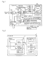
- FIG. 1 is a block diagram showing an internal configuration of a system LSI described in Document 1.
- the system LSI in FIG. 1 includes MPU core (control circuit) 91, built-in RAM (Random Access Memory, storage circuit) 92 that stores the program for operating MPU core 91, peripheral circuit 93 for performing transmission and reception of signals with MPU core 91.
- the system LSI is also connected to system LSI peripheral apparatus 5, so that the two transmit and receive signals to and from each other.
- Built-in RAM 92 also incorporates a debug supporting function program in addition to other than the program for operating MPU core 91.
- debug supporting circuit 914 incorporating signal selection circuit 931 is provided inside MPU core 91.
- Peripheral circuit 93 incorporates signal selection circuit 932.
- signal selection circuit 933 for selecting a final monitor signal is provided. The selecting operation of each of signal selection circuits 931 to 933 is controlled by monitor signal control circuit 4.
- the system LSI in Document 1 includes signal selection circuit 931 for selecting any one of the internal signals in MPU core 91, signal selection circuit 932 for selecting any one of the internal signals in peripheral circuit 93 and signal selection circuit 933 for selecting either one of the outputs from these signal selection circuits 931 and 932, and the system LSI can arbitrarily switch the selecting operation of each of signal selection circuits 931 to 933 as required. Accordingly, it is possible to analyze in detail the internal operation of the system LSI in real-time. Further, even if the monitoring terminals are limited, it is possible to easily switch and output a plurality of monitoring signals.
- the tracing system disclosed in Document 1 operates on the premise that trace data is output to the outside of the LSI, so that the amount of observable trace data per unit time is limited by the speed of the communication line to the outside, the built-in buffer capacity and the like. Accordingly, there occurs a case in which a desired operation cannot be checked in a system or the like that internal operation speed is high.
- the signals to be observed are limited to those selected so as to reduce the amount of trace data, it is impossible to make a decision in a particular condition based on behaviors of all the signals to be observed.
- One object of the present invention is to provide a means for enabling observation of a desired operation while observing arbitrary signals to be observed, without being affected by the speed of the connected communication line and by the built-in buffer capacity.
- a semiconductor integrated circuit is a semiconductor integrated circuit having a debugging function, and includes:
- a debug/trace circuit of the present invention is a debug/trace circuit built in a semiconductor integrated circuit including a main functional structure that executes continuous predetermined operations to continuously generate events associated with said operations, and includes:
- An operation observing method for a semiconductor integrated circuit of the present invention is an operation observing method for a semiconductor integrated circuit to observe the operation of a main functional structure by a debug/trace circuit built in a semiconductor integrated circuit including a main functional structure that executes continuous predetermined operations to continuously generate events associated with said operations, and includes the steps of:
- FIG. 2 is a block diagram showing an overall configuration of a debug/trace system according to the first exemplary embodiment of the present invention.
- system LSI 1 includes main functional structure 2 and debug/trace circuit 3.
- the system LSIs mentioned herein may include configurations having a plurality of chips integrated therein, such as SiP (System in Package), MCP (Multi Chip Module), PoP (Package on Package) and the like. It is also assumed that the system LSI has a typical configuration in which the capacity of communication inside the system LSI is high enough compared to the capacity of communication to the outside of the LSI.
- Main functional structure 2 is a circuit for realizing essential desired functions of system LSI 1, and is made up of MPU core 21 and peripheral circuit 22 as a typical example.
- Debug/trace circuit 3 includes event detector 31, controller 32 and control information list holder 33.
- Control information list holder 33 holds control information list 4.
- FIG. 3 is a structural diagram showing a control information list in the first exemplary embodiment. Details of control information list 4 stored in control information list holder 33 will be described using FIG. 3 .
- Control information list 4 is a list having a plurality of entries 41 arranged therein, each entry 41 being composed of detection condition indicator 42 and operation indicator 43.
- Detection condition indicator 42 describes the condition for detecting an event to be observed. It is possible to detect an event (target event) that meets the detection condition by comparing an occurring event with the detection condition.
- Operation indicator 43 describes the operation of controller 32 when a target event has been detected. Examples of the described operation of controller 32 include indication as to data output, indication as to change of the entry to be next referred to, indication to end the measurement, indication to output data to the outside of the LSI (which will hereinbelow be referred to as simply "the outside"), indication to output control information to the outside, and the like.
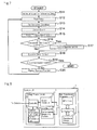
- FIG. 4 is a flow chart showing a processing flow of a debug/trace system in the first exemplary embodiment. The operation of the debug/trace system of the present exemplary embodiment will be described based on the flow chart in FIG. 4 .
- controller 32 when controller 32 receives an observation start command from the outside, controller 32 initializes the entry readout position from control information list 4 held in controller 32 itself (Step S1). At this time, a value of the top entry in control information list 4 is usually designated, but another value may be designated depending on use.
- controller 32 reads out one entry 41 from control information list 4 held in control information list holder 33 and holds the value therein (Step S2). Then, controller 32 sets up detection condition for event detector 31 in accordance with detection condition indicator 42 of the retrieved entry 41 (Step S3).
- event detector 31 continues comparing events with the set detection condition, and gives an event detection notice to controller 32 when detecting an event that meets the condition for notifying event occurrence (Step S4).
- the condition for notifying event occurrence is the condition which indicates whether or not occurrence of an event is notified to controller 32. For example, a notice of occurrence of an event may be given only when the event meets the detection condition or a notice of occurrence of an event may be given in either case where the event meets or does not meet the detection condition. Also, event detector 31 holds detailed information on events therein.
- controller 32 refers to operation indicator 43 of entry 41 (Step S5) and performs control operations in accordance with an indication of operation indicator 43 (Step S6).
- Examples of the control operation include reading detailed information of an event from event detector 31 to output it as event data, outputting user data written in control information list 4, outputting control information, typified by error notice and normal end notice, and others.
- Controller 32 further determines whether or not an end command is included in the indication from operation indicator 43 of entry 41 (Step S7). If an end command is included in the indication, controller 32 ends the measurement. If no end command is included in the indication, controller 32 changes the entry readout position as required (Step S8), and returns to read out a next entry 41.
- control information list 4 including a plurality of entries 41 corresponding to a series of operations that need to be checked has been prepared in advance and since the event detection condition and control are changed one to another in accordance with control information list 4, it is possible to internally check based on many signal variations that particular events have occurred in a particular order and record the trace data. As a result, it becomes possible to trace the event sequences inside the system LSI, hence it is possible to check desired operations while observing arbitrary signals of a high-speed observation target without being affected by the speed of the communication line and by the built-in buffer capacity.
- FIG. 5 is a block diagram showing an overall configuration of the second exemplary embodiment of the present invention.
- main functional structure 21 is composed of operational units such as MPU core 21, DSP, accelerators and the like, each executing a predetermined series of operations.
- the system LSI of the present exemplary embodiment includes operational unit controller 34 in debug/trace circuit 3, in addition to the first exemplary embodiment shown in FIG. 2 .
- Operational unit controller 34 transmits signals for controlling the operational units in main functional structure 2.
- FIG. 6 is a structural diagram showing a control information list in the second exemplary embodiment.
- operational unit control indicator 431 exists inside operation indicator 43 of control information list 4.
- Information written in operational unit control indicator 431 is information on which operational unit inside main functional structure 2 an indication is given to, what kind of a control indication is given or no indication is given, for operational unit controller 34. Examples of control indication include stop command, start command, etc.
- FIG. 7 is a flow chart showing a process flow of a debug/trace system in the second exemplary embodiment. The operation of the debug/trace system of the second exemplary embodiment will be described based on the flow chart in FIG. 7 .
- controller 32 when controller 32 receives an observation start command from the outside, controller 32 initializes the entry readout position from a control information list held in itself (Step S11). At this time, the top event in the control information list is usually designated, but another value may be designated depending on use.
- controller 32 reads out one entry 41 from control information list 4 held in control information list holder 33 and holds the value therein (Step S12). Then, controller 32 sets up a detection condition for event detector 31 in accordance with detection condition indicator 42 of the retrieved entry 41 (Step S13).
- event detector 31 continues comparing events with the set detection condition and gives an event detection notice to controller 32 when an event meets the condition for notifying event occurrence (Step S14).
- the condition for notifying event occurrence is the condition on which whether or not the occurrence of an event is notified to controller 32. For example, a notice of occurrence of an event may be given only when the event meets the detection condition or a notice of occurrence of an event may be given in both cases where the event meets and does not meet the detection condition.
- Event detector 31 also holds detailed information on events therein.
- controller 32 determines whether or not any control command to an operational unit exits (Step S16). If there is any control command to an operational unit, controller 32 transmits the operational unit control command to operational unit controller 34. Operational unit controller 34, in accordance with the indication of the received operational unit control command, performs a control operation to the operational unit inside main functional structure 2 (Step S17). Examples of control on an operational unit include suspension, activation, status check and the like of the operational unit.
- controller 32 When no control command to an operational unit existed at the determination of Step S16, or after the control operation at Step S17, controller 32 performs other control operations in accordance with the indication of operation indicator 43 of entry 41 (Step S18). Examples of other control operations include reading detailed information of an event from event detector 31 to output the data, outputting user data written in control information list 4, performing control output, typified by error notice and normal end notice, and others.
- Controller 32 further determines whether or not an end command is included in the indication from operation indicator 43 of entry 41 (Step S19). If an end command is included in the indication, controller 32 ends the measurement. If no end command is included in the indication, controller 32 changes the entry readout position as required (Step S20), and returns to readout of next entry.
- control information list 4 includes a control command to a particular operational unit suited to the event to be checked.
- control information list 4 includes a control command to a particular operational unit suited to the event to be checked.
- FIG. 8 is a block diagram showing an overall configuration of the third exemplary embodiment of the present invention.
- the system LSI of the present exemplary embodiment includes performance measuring portion 35 in addition to the first exemplary embodiment shown in FIG. 2 .
- Performance measuring portion 35 measures performance such the frequency of occurrence of events, the amount of bus traffic, the delay values and the like, in accordance with the input command information.
- FIG. 9 is a structural diagram showing a control information list in the third exemplary embodiment. As shown in the control information list structural diagram of FIG. 9 , performance measurement control indicator 432 exists inside operation indicator 43 of control information list 4. Written in performance measurement control indicator 432 is command information to performance measuring portion 35 to control performance measurement. Examples of command information include a command for setting up a parameter that indicates what kind of performance measurement is performed and a command for starting or ending the performance measurement.
- FIG. 10 is a flow chart showing a process flow of a debug/trace system in the third exemplary embodiment. The operation of the debug/trace system of the third exemplary embodiment will be described based on the flow chart in FIG. 10 .
- controller 32 when controller 32 receives an observation start command from the outside, controller 32 initializes the entry readout position from a control information list held in itself (Step S21). At this time, the top entry in the control information list is usually designated, but another value may be designated depending on use.
- controller 32 reads out one entry 41 from control information list 4 held in control information list holder 33 and holds the value therein (Step S22). Then, controller 32 sets up detection condition for event detector 31 in accordance with detection condition indicator 42 of retrieved entry 41 (Step S23).
- event detector 31 continues comparing events with the set detection condition and gives an event detection notice to controller 32 when an event meets the condition for notifying event occurrence (Step S24).
- the condition for notifying event occurrence is the condition on which whether or not occurrence of an event is notified to controller 32. For example, a notice of occurrence of an event may be given only when the event meets the detection condition or a notice of occurrence of an event may be given in both cases where the event meets and does not meet the detection condition.
- Event detector 31 also holds detailed information on events.
- controller 32 determines whether or not there is any command information on performance measurement(Step S26).
- controller 32 transmits the command information as to performance measurement to performance measuring portion 35.
- Performance measuring portion 35 in accordance with the command information received from controller 32, controls performance measurement (Step S27). Examples of performance measurement control include setup of measurement targets and measurement items, starting and ending of measurement, and the like.
- controller 32 When there is no control command as to performance measurement existed at the determination of Step S26, or after the control operation at Step S27, controller 32 performs other control operations in accordance with the content of indication of operation indicator 43 of entry 41 (Step S28). Examples of other control operations include reading detailed information of an event from event detector 31 to output the data, outputting user data written in control information list 4, performing control output, typified by error notice and normal end notice, and others.
- Controller 32 further determines whether or not an end command is included in the indication from operation indicator 43 of entry 41 (Step S29). If an end command is included in the content of indication, controller 32 ends the measurement. If no end command is included in the indication, controller 32 changes the entry readout position as required (Step S30), and returns to readout of the next entry.
- the present exemplary embodiment in addition to the function of tracing event sequences similarly to the first exemplary embodiment, further includes performance measuring portion 35, and performance measurement control indicator 432 is introduced in control information list 4 to use control information list 4 that includes a control command as to performance measurement suited to the event to be checked.
- control information list 4 that includes a control command as to performance measurement suited to the event to be checked.
- FIG. 11 is a block diagram showing a specific configuration of event detector 31 and controller 32.
- event detector 31 is composed of detection condition holder 311, condition determinater 312 and event holder 313.
- Detection condition holder 311 holds condition for detecting events.
- Condition determinater 312 observes the signals from main functional structure 2 to controller 32 to determine whether or not each event meets the detection condition held at detection condition holder 311. When an event meets the detection condition, condition determinater 312 sends an event detection notice to controller 32.
- Event holder 313 holds the details of the event detected by condition determinater 312.
- event detector 31 holds the detection condition set from controller 32 in detection condition holder 311, detects occurrence of an event at condition determinater 312 if an event that matches the detection condition occurs, and holds the details of the event at event holder 313.
- controller 32 is composed of control executor 321, entry readout position holder 322 and entry information holder 323.
- Control executor 321 performs control in accordance with control information list 4 and gives operation indications to each portion in association with it.
- Entry readout position holder 322 holds the position of control information entry 4 to be read out next from control information list holder 33.
- Entry information holder 323 holds the information of entry 4 read out from control information list holder 33.
- controller 32 reads out entry 4 designated by the positional information held at entry readout position holder 322, from control information list holder 33, holds it in entry information holder 323 and performs control in accordance with entry 4 held at entry information holder 323.
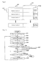
- FIG. 12 is a flow chart showing a process flow of a debug/trace system in the first example.
- FIG. 13 is a structural diagram showing a control information list in the first example.
- Step S32 to Step S34 in FIG. 12 correspond to Step S2 in FIG. 4 .
- Step S35 to Step S36 correspond to Step S3 in FIG. 4 .
- Step S37 to Step S40 correspond to Step S4 in FIG. 4 .
- operation indicator 43 incorporates hit control indicator 433, hit output indicator 434, mishit control indicator 438 and mishit output indicator 439.
- Hit control indicator 433 is an operation indication for specifying the operation inside debug/trace circuit 3 when an event meeting the detection condition was detected (at the time of hit).
- Hit output indicator 434 is information for designating whether or not event data at the time of hit is output.
- Mishit control indicator 438 is an operation indication for specifying the operation when an event other than the detection condition was detected (at the time of mishit).
- Mishit output indicator 439 is information for designating whether or not event data at the time of mishit is output.
- one hit control indicator 433 and one hit output indicator 434 are shown.
- the present invention should not be limited to this.
- entries 41 such that a plurality of detection conditions can be set in detection condition indicator 42 and a plurality of hit control indicators 433 and hit output indicators 434 can be set in operation indicator 43. With this construction, it is possible to set up entries 41 so as to perform a different process depending on the content of the detected event.
- control executor 321 sets the initial value into entry readout position holder 322 (Step S31).
- entry readout position holder 322 is set with the initial value, the position from which an entry is read out from control information list 4 is initialized.
- the top in control information list 4 is usually designated, but another value may be designated depending on use.
- controller 32 gives notice of the readout position from entry readout position holder 322 to control information list holder 33 (Step S32).
- Control information list holder 33 outputs entry 41 corresponding to the notified readout position (Step S33).
- Controller 32 stores entry 41 output from control information list holder 33 into entry information holder 323 located inside (Step S34).
- control executor 321 refers to detection condition indicator 42 of entry 41 stored in entry information holder 323 (Step S35) and writes the detection condition indicated therein into detection condition holder 311 of event detector 31 (Step S36).
- condition determinater 312 in event detector 31 determines whether or not the change meets the condition for notifying an event, based on the observation result of the signal and the detection condition held at detection condition holder 311 (Step S38). If any occurrence of an event that meets the notice condition is not detected when the notice condition is confirmed, condition determinater 312, returning to Step S37, repeats the same process until an event that meets the notice condition occurs. On the other hand, when occurrence of an event that meets the notice condition is detected when the notice condition is confirmed, condition determinater 312 transmits an event detection notice to controller 32 (Step S39).
- control executor 321 determines whether it is a hit notice or a mishit notice (Step S41).
- a hit notice is information which, when the notice condition includes information that the detection condition is satisfied, gives notice that the notice condition (detection condition) was satisfied.
- a mishit notice is information which, when the notice condition includes information that the detection condition is not satisfied, gives notice that the notice condition was satisfied (that is, detection condition was not satisfied).
- control executor 321 acquires the content of the control to be performed by referring to hit control indicator 433 of entry 41 stored in entry information holder 323, and acquires the information as to whether or not event data needs to be output by referring to hit output indicator 434 (Step S42).
- control executor 321 acquires the content of the control to be performed by referring to mishit control indicator 438 of entry 41 stored in entry information holder 323, and acquires the information as to whether or not event data needs to be output by referring to mishit output indicator 439 (Step S43).
- control executor 321 determines whether or not event data needs to be output, based on the information acquired at Step S42 or Step S43 (Step S44). If event data needs to be output, control executor 321 reads out the detailed information on the stored events from event holder 313 of event detector 31 and outputs the necessary information as event data (Step S45).
- control executor 321 executes control in accordance with the control content acquired at Step S42 or Step S43 (Step S46).
- the control content has been given in hit control indicator 433 or in mishit control indicator 438.
- control executor 321 When the indication is "no change", control executor 321 returns to Step S32 without doing anything. If the indication is "to the next”, control executor 321 rewrites the value in entry readout position holder 322 to the value that represents the position of the next entry (Step S47), and returns to Step S32. If the indication is "end”, control executor 321 outputs an end notice to the outside (Step S48) and ends the measurement.
- Step S41 For example, if event detector 31 is specified to operate such as to send an event detection notice at Step S39 only when the observed result has satisfied the detection condition at Step S38, no transition from Step S41 to Step S43 will occur on the control executor 321 side.
- event detector 31 is specified to operate such as to send an event detection notice when the observed result has satisfied the detection condition or not at Step S38, event detector 31 will never perform a repeating operation on the "No" route to return to Step S37.
- event detector 31 is specified to send an event detection notice to controller 32 when the notice condition is satisfied and to define the scope for hit notice within the notice condition, there is a chance that both event detector 31 and controller 32 will execute all the steps shown in FIG. 12 .
- control information list 4 shown in FIG. 13 an example in which the fact that the signal from main functional structure 2 has agreed with the set value as a detection condition is handled as the event that satisfies the detection condition will be illustrated.
- a particular access to a bus, memory, or a register of a peripheral circuit is regarded as an event that meets the detection condition.
- access-related events an access to a particular address, an access having data of a particular value, an access from a particular operational unit, and others are able to be set as the event to be detected.
- the value of a timer, counter or register having taken a predetermined value is regarded as an event that meets the detection condition.
- One particular value may be set as the detection condition, but another method also may be applicable.
- a range is set with an upper limit and a lower limit.
- a particular set value of a plurality of bits is designated and a mask value is used so as to determine whether each bit of the set value is made valid or invalid when compared to the observation signal.
- a bit map is used to determine whether comparison is made valid or invalid for every accessor.
- control information list 4 includes three entries 411, 412 and 413.
- Detection condition indicator 42 of entry 411 is set with "bus access to address A”. Accordingly, if there is a bus access to address A, it is detected as an event of entry 411. Similarly, detection condition indicator 42 of entry 412 is set with "bus access to address B”. Detection condition indicator 42 of entry 413 is set with "bus access to address C”.
- Hit control indicators 433 of entry 411 and entry 412 are set with "to the next". "To the next” indicates going forward to monitor the next entry. Accordingly, when, for instance, an event of entry 411 is hit, the control goes to monitor the next entry 412. Similarly, when an event of entry 412 is hit, the control goes to monitor the next entry 413.
- Hit control indicator 433 of entry 413 is set with "end". "End” indicates that the measurement is completed at that point. Accordingly, if an event of entry 413 is hit, the measurement is ended at that point.
- Hit output indicators 434 of entries 411 to 413 are set with "output". "Output" indicates outputting of event data. Accordingly, when, for instance, an event of entry 411 is hit, the event data at that time is output. Similarly, when an event of entry 412 is hit, the event data at that time is output. When an event of entry 413 is hit, the event data at that time is output.
- Mishit control indicator 438 of entries 411, 412 and 413 are set with “no change” while mishit output indicator 439 are set with “no output”.
- "No change” indicates continuation of monitoring the same entry without changing the entry.
- "No output” indicates non-outputting of event data. Accordingly, when, for instance, no event of entry 411 is hit, monitoring the event of entry 411 is continued as is while no event data will be output. Similarly, when no event of entry 412 is hit, monitoring the event of entry 412 is continued as is while no event data will be output. When no event of entry 413 is hit, monitoring the event of entry 413 is continued as is while no event data will be output.
- entry 411 is designated as the initial value of the entry to be referred to first.
- the signal from main functional structure 2 is one other than bus access to address A, the state of waiting for a bus access to address A to be observed continues without changing the entry to be referred to as the monitoring target and without outputting event data.
- the state of waiting for a bus access to address B to be observed continues.
- its event data is output and the operation goes to the observation referring to entry 413.
- the event data is output to end the measurement.
- control information list 4 thus set as in FIG. 13 makes it possible to acquire the event data (e.g. data value) of each bus access as the trace data when bus accesses occurred in the order of addresses A, B and C, being mixed with various events during execution of a certain program. Since no unnecessary data will be acquired, the buffer capacity required for data recording can be markedly cut down. Further, since event detection and data recording can be done following control information list 4 without the need of successive operations from the outside of the system LSI, the operation will not be limited by the speed of the communication line to the outside.
- event data e.g. data value
- event detector 31 and controller 32 of the second example are the same as those of the first example shown in FIG. 11 .
- FIG. 14 is a flow chart showing a process flow of a debug/trace system in the second example.
- FIG. 15 is a structural diagram showing a control information list in the second example.
- Step S52 to Step S54 in FIG. 14 correspond to Step S2 in FIG. 4 .
- Step S55 to Step S56 correspond to Step S3 in FIG. 4 .
- Step S57 to Step S60 correspond to Step S4 in FIG. 4 .
- operation indicator 43 incorporates hit control indicator 433, hit output indicator 434, mishit control indicator 438 and mishit output indicator 439.
- Hit control indicator 433 is an operation indication for specifying the operation inside debug/trace circuit 3 when an event meeting the detection condition was detected (at the time of hit).
- Hit output indicator 434 is information for designating whether or not event data at the time of hit is output.
- Mishit control indicator 438 is an operation indication for specifying the operation when an event other than the detection condition is detected (at the time of mishit).
- Mishit output indicator 439 is information for designating whether or not event data at the time of mishit is output.
- one hit control indicator 433 and one hit output indicator 434 are shown.
- the present invention should not be limited to this.
- entries 41 such that a plurality of detection conditions can be set in detection condition indicator 42 and a plurality of hit control indicators 433 and hit output indicators 434 can be set in operation indicator 43. With this construction, it is possible to set up entries 41 so as to perform a different process depending on the content of the detected event.
- control executor 321 sets the initial value into entry readout position holder 322 (Step S51).
- entry readout position holder 322 is set with the initial value, the position from which an entry is read out from control information list 4 is initialized.
- the top in control information list 4 is usually designated, but another value may be designated depending on use.
- controller 32 gives notice of the readout position from entry readout position holder 322 to control information list holder 33 (Step S52).
- Control information list holder 33 outputs entry 41 corresponding to the notified readout position (Step S53).
- Controller 32 stores entry 41 output from control information list holder 33 into entry information holder 323 located inside (Step S54).
- control executor 321 refers to detection condition indicator 42 of entry 41 stored in entry information holder 323 (Step S55) and writes the detection condition indicated therein into detection condition holder 311 of event detector 31 (Step S56).
- condition determinater 312 in event detector 31 determines whether or not the change meets the condition for notifying an event, based on the observation result of the signal and the detection condition held at detection condition holder 311 (Step S58). If any occurrence of an event that meets the notice condition is not detected when the notice condition is confirmed, condition determinater 312, returning to Step S57, repeats the same process until an event that meets the notice condition occurs. On the other hand, when occurrence of an event that meets the notice condition is detected when the notice condition is confirmed, condition determinater 312 transmits an event detection notice to controller 32 (Step S59).
- control executor 321 determines whether it is a hit notice or a mishit notice (Step S61).
- a hit notice is information which, when the notice condition includes information that the detection condition is satisfied, gives notice that the notice condition (detection condition) was satisfied.
- a mishit notice is information which, when the notice condition includes information that the detection condition is not satisfied, gives notice that the notice condition was satisfied (that is, detection condition was not satisfied).
- control executor 321 acquires the content of the control to be performed by referring to hit control indicator 433 of entry 41 stored in entry information holder 323, and acquires the information as to whether or not event data needs to be output by referring to hit output indicator 434 (Step S62).
- control executor 321 acquires the content of the control to be performed by referring to mishit control indicator 438 of entry 41 stored in entry information holder 323, and acquires the information as to whether or not event data needs to be output by referring to mishit output indicator 439 (Step S63).
- control executor 321 determines whether or not event data needs to be output, based on the information acquired at Step S42 or Step S63 (Step S64). If event data needs to be output, control executor 321 reads out the detailed information on the stored events from event holder 313 of event detector 31 and outputs the necessary information as event data (Step S65).
- control executor 321 executes control in accordance with the control content acquired at Step S62 or Step S63 (Step S66).
- the control content has been given in hit control indicator 433 or in mishit control indicator 438.
- control executor 321 When the indication is "no change", control executor 321 returns to Step S52 without doing anything. If the content of indication is "to the next”, control executor 321 rewrites the value in entry readout position holder 322 to the value that represents the position of the next entry (Step S67), and returns to Step S52. If the content of indication is "move”, control executor 321 rewrites the value in entry readout position holder 322 to the value that represents the designated entry readout position, and returns to Step S52. If the content of indication is "end”, control executor 321 outputs an end notice to the outside (Step S69) and ends the measurement. If the content of indication is "error”, control executor 321 outputs an error notice to the outside (Step S70) and ends the measurement.
- control information list 4 shown in FIG. 15 .
- an example in which a change of a particular signal from main functional structure 2 is handled as the event that satisfies the detection condition will be illustrated.
- a cut-in signal or control signal becomes valid or invalid is regarded as an event that meets the detection condition.
- a certain operational unit changes in state is regarded as an event.
- the event detection condition may be set for one particular signal as a detection condition, another method also may be applicable.
- another method there is a conceivable method in which the values of detection conditions for a plurality of events are designated, and a bit map is used to set whether these are made valid or invalid for each event. This arrangement makes it possible to designate a particular event group.
- control information list 4 includes three entries 414, 415, 416 and 417.
- Detection condition indicator 42 of entry 414 is set with "event A”. Accordingly, if event address A occurs, it is detected as an event of entry 414. Similarly, detection condition indicator 42 of entry 415 is set with “event B”. Detection condition indicator 42 of entry 416 is set with “event C”. Detection condition indicator 42 of entry 417 is set with "event D”.
- Hit control indicators 433 of entry 414, entry 415 and entry 416 are set with "to the next". "To the next” indicates going forward to monitor the next entry. Accordingly, when, for instance, an event of entry 414 is hit, the control goes to monitor the next entry 415. Similarly, when an event of entry 415 is hit, the control goes to monitor the next entry 416. When an event of entry 416 is hit, the control goes to monitor the next entry 417.
- Hit control indicator 433 of entry 417 is set with "end". "End” indicates that the measurement is completed at that point. Accordingly, if an event of entry 417 is hit, the measurement is ended at that point.
- Hit output indicators 434 of entries 414 to 417 and mishit output indicator 439 of entries 415 to 417 are set with "output". "Output" indicates outputting of event data. Accordingly, when, for instance, an event of entry 414 is hit, the event data at that time is output. Similarly, when an event of entry 415, 416 or 417 is hit, the event data at that time is output. When an event of entry 415, 416 or 417 is mishit, the event data at that time is output.
- Mishit control indicators 438 of entries 414 and 417 are set with "no change". "No change" indicates continuation of monitoring the same entry without changing the entry. Accordingly, when no event of entry 414 or 417 is hit, monitoring the event of entry 414 is continued as is.
- Mishit output indicator 439 of entry 414 is set with "no output". "No output” indicates non-outputting of event data. Accordingly, when no event of entry 414 is hit, no event data will be output.
- Mishit control indicator 438 of entry 415 is set with "error". "Error” indicates giving an error notice to the outside and ending the measurement at that point. Accordingly, when an event of entry 415 is mishit, an error notice is output and the measurement is ended at that point.
- Mishit control indicator 438 of entry 416 is set with “move to 414". "Move” indicates going forward to monitor a designated entry. In this case, "414" is designated as the destination. Accordingly, when an event of entry 416 is mishit, the control goes to monitor entry 414.
- entry 414 is designated as the initial value of the entry to be referred to first.
- monitoring of event A is started. If the detected event is other than event A, the entry to be referred to as the monitoring target is not changed and no event data is output, and the state of waiting for event A to be observed continues.
- event A occurs, an event of entry 414 is detected. As a result, the entry to be referred to is changed to entry 415, and event data is output.
- the event data is information associated with the detected event, for example.
- entry 415 When a next event is observed after event A has been observed, the content of entry 415 is referred to.
- entry 415 an error notice is output when an event other than event B was detected, and the event data is output to end the measurement.
- the measurement was terminated due to error, it is possible to check what happened by examining the event data.
- entry to be referred to is changed to entry 416 and event data is output.
- event data is output.
- entry 416 the operation returns to entry 414 so that monitoring of event A is started when an event other than event C is detected. Though the fact that an event is other than event C is not an error, because it is not the trace condition either, the operation is started once again from monitoring of event A.
- entry 417 When event C was detected, then the content of entry 417 is referred to.
- entry 417 when an event other than event D is detected, the event data is output but the entry to be referred to will not be changed. As a result, the event data of all the events will be recorded as trace data until event D is detected. When event D is detected, an end notice is output to terminate the measurement at that point.
- control information list 4 thus set as in FIG. 15 makes it possible to start tracing of events when events A, B and C have occurred in succession during execution of a certain program and terminate the trace when event D occurs.
Landscapes
- Engineering & Computer Science (AREA)
- Theoretical Computer Science (AREA)
- Computer Hardware Design (AREA)
- General Engineering & Computer Science (AREA)
- Quality & Reliability (AREA)
- Physics & Mathematics (AREA)
- General Physics & Mathematics (AREA)
- Debugging And Monitoring (AREA)
- Test And Diagnosis Of Digital Computers (AREA)
Applications Claiming Priority (2)
| Application Number | Priority Date | Filing Date | Title |
|---|---|---|---|
| JP2007033340 | 2007-02-14 | ||
| PCT/JP2008/051078 WO2008099657A1 (fr) | 2007-02-14 | 2008-01-25 | Circuit intégré à semi-conducteur, circuit de débogage/dépistage des anomalies et procédé d'observation du fonctionnement d'un circuit intégré à semi-conducteur |
Publications (2)
| Publication Number | Publication Date |
|---|---|
| EP2124149A1 true EP2124149A1 (fr) | 2009-11-25 |
| EP2124149A4 EP2124149A4 (fr) | 2012-11-14 |
Family
ID=39689903
Family Applications (1)
| Application Number | Title | Priority Date | Filing Date |
|---|---|---|---|
| EP08703905A Withdrawn EP2124149A4 (fr) | 2007-02-14 | 2008-01-25 | Circuit intégré à semi-conducteur, circuit de débogage/dépistage des anomalies et procédé d'observation du fonctionnement d'un circuit intégré à semi-conducteur |
Country Status (6)
| Country | Link |
|---|---|
| US (1) | US7911216B2 (fr) |
| EP (1) | EP2124149A4 (fr) |
| JP (1) | JP5151996B2 (fr) |
| KR (1) | KR101090556B1 (fr) |
| CN (1) | CN101606132B (fr) |
| WO (1) | WO2008099657A1 (fr) |
Families Citing this family (7)
| Publication number | Priority date | Publication date | Assignee | Title |
|---|---|---|---|---|
| CN102782658B (zh) * | 2010-03-05 | 2015-03-18 | 三菱电机株式会社 | 程序跟踪装置 |
| JP5884729B2 (ja) * | 2010-04-27 | 2016-03-15 | 日本電気株式会社 | 論理回路エミュレータ及び論理回路エミュレータの制御方法 |
| JP6052847B2 (ja) * | 2012-02-24 | 2016-12-27 | Necプラットフォームズ株式会社 | トランザクション処理装置及び不正トランザクション検出方法 |
| US9377507B2 (en) * | 2012-05-07 | 2016-06-28 | Microchip Technology Incorporated | Processor device with instruction trace capabilities |
| JP2016025649A (ja) * | 2014-07-24 | 2016-02-08 | 富士通株式会社 | 電子装置及び機器検知方法 |
| KR102522154B1 (ko) * | 2016-03-15 | 2023-04-17 | 에스케이하이닉스 주식회사 | 반도체 메모리 장치의 컨트롤러 및 이의 동작 방법 |
| US12072378B2 (en) * | 2019-12-09 | 2024-08-27 | Advanced Micro Devices, Inc. | Debug state machine triggered extended performance monitor counter |
Family Cites Families (13)
| Publication number | Priority date | Publication date | Assignee | Title |
|---|---|---|---|---|
| JPH01288931A (ja) | 1988-05-16 | 1989-11-21 | Nec Corp | Pl/iプログラムのデバック方式 |
| JPH05100891A (ja) | 1991-10-09 | 1993-04-23 | Kobe Nippon Denki Software Kk | プログラムデバツグ装置 |
| JPH09305443A (ja) * | 1996-05-13 | 1997-11-28 | Omron Corp | プロセス監視装置およびプロセス監視方法 |
| US6557119B1 (en) | 1999-10-01 | 2003-04-29 | Stmicroelectronics Limited | Microcomputer debug architecture and method |
| JP4212224B2 (ja) | 2000-07-10 | 2009-01-21 | 株式会社東芝 | 半導体集積回路 |
| JP3913470B2 (ja) * | 2000-12-28 | 2007-05-09 | 株式会社東芝 | システムlsi |
| JP2003263340A (ja) | 2002-03-11 | 2003-09-19 | Ricoh Co Ltd | デバッグ装置 |
| US7149926B2 (en) * | 2003-05-22 | 2006-12-12 | Infineon Technologies Ag | Configurable real-time trace port for embedded processors |
| JP4874440B2 (ja) | 2004-06-29 | 2012-02-15 | 株式会社デンソー | 状態とイベントの組にアクションを割り当てた対応情報に基づいてプログラムを生成するプログラム生成プログラム、プログラム生成装置、およびプログラム生成方法、ならびに、これらによって生成されるプログラム |
| JP2006338305A (ja) * | 2005-06-01 | 2006-12-14 | Toshiba Corp | 監視装置及び監視プログラム |
| JP2006336305A (ja) | 2005-06-02 | 2006-12-14 | Shin Caterpillar Mitsubishi Ltd | 作業機械 |
| JP4523508B2 (ja) | 2005-07-28 | 2010-08-11 | 長野計器株式会社 | 測定器及びその製造方法 |
| JP5067111B2 (ja) * | 2007-10-18 | 2012-11-07 | 富士通セミコンダクター株式会社 | 半導体集積回路及びデバッグモード決定方法 |
-
2008
- 2008-01-25 WO PCT/JP2008/051078 patent/WO2008099657A1/fr not_active Ceased
- 2008-01-25 US US12/525,953 patent/US7911216B2/en active Active
- 2008-01-25 EP EP08703905A patent/EP2124149A4/fr not_active Withdrawn
- 2008-01-25 KR KR1020097019084A patent/KR101090556B1/ko not_active Expired - Fee Related
- 2008-01-25 CN CN2008800046347A patent/CN101606132B/zh not_active Expired - Fee Related
- 2008-01-25 JP JP2008558029A patent/JP5151996B2/ja not_active Expired - Fee Related
Also Published As
| Publication number | Publication date |
|---|---|
| CN101606132A (zh) | 2009-12-16 |
| WO2008099657A1 (fr) | 2008-08-21 |
| US7911216B2 (en) | 2011-03-22 |
| US20100321051A1 (en) | 2010-12-23 |
| JP5151996B2 (ja) | 2013-02-27 |
| EP2124149A4 (fr) | 2012-11-14 |
| CN101606132B (zh) | 2012-05-30 |
| KR101090556B1 (ko) | 2011-12-08 |
| JPWO2008099657A1 (ja) | 2010-05-27 |
| KR20090121321A (ko) | 2009-11-25 |
Similar Documents
| Publication | Publication Date | Title |
|---|---|---|
| EP2124149A1 (fr) | Circuit intégré à semi-conducteur, circuit de débogage/dépistage des anomalies et procédé d'observation du fonctionnement d'un circuit intégré à semi-conducteur | |
| US6519310B2 (en) | Hardware event based flow control of counters | |
| US20020026553A1 (en) | One-chip system large-scale integrated circuit including processor circuit and its peripheral circuits | |
| JP2008287319A (ja) | 半導体デバイス、電子装置及びアクセスログ取得方法 | |
| CN119829490B (zh) | 片上逻辑分析仪的数据缓存方法以及相关装置 | |
| US20060150023A1 (en) | Debugging apparatus | |
| JP6503889B2 (ja) | 演算処理装置、情報処理装置および演算処理装置の制御方法 | |
| JP2007233593A (ja) | ロギングシステム | |
| JP2005222446A (ja) | オンボードデバッグ装置および半導体回路装置 | |
| JP5505781B2 (ja) | トレース・障害観測システム、トレース・障害観測方法及びトレース・障害観測プログラム | |
| JP7516974B2 (ja) | 電子機器用デバイス、電子機器用デバイスの制御方法および電子機器用デバイスの制御プログラム | |
| KR100400957B1 (ko) | 집적회로 내부신호 감시장치 | |
| CN119889411B (zh) | 一种存储测试装置及其测试方法 | |
| CN119621492B (zh) | 一种基于锚点的离散式抓取桶的dfx方法 | |
| CN109697144B (zh) | 一种电子设备的硬盘检测方法及电子设备 | |
| JP2006185365A (ja) | 半導体装置およびデバッグ方法 | |
| CN119849393A (zh) | 片上逻辑分析仪的实时数据读写方法以及相关装置 | |
| CN121091051A (zh) | 信号处理装置、信号处理方法和信号处理设备 | |
| JP2009529722A (ja) | 追跡データを生成するための機器、方法、およびコンピュータ・プログラム製品 | |
| JP4899620B2 (ja) | バストレース方式 | |
| US20030115523A1 (en) | Apparatus and method for analysis and troubleshooting of electronic devices | |
| JP2011258055A (ja) | 情報処理システム及び情報処理システムの障害処理方法 | |
| JPH0736735A (ja) | デバッグ装置 | |
| JPH09237201A (ja) | マイクロコンピュータアナライザ | |
| JPH11134261A (ja) | 入出力制御装置 |
Legal Events
| Date | Code | Title | Description |
|---|---|---|---|
| PUAI | Public reference made under article 153(3) epc to a published international application that has entered the european phase |
Free format text: ORIGINAL CODE: 0009012 |
|
| 17P | Request for examination filed |
Effective date: 20090911 |
|
| AK | Designated contracting states |
Kind code of ref document: A1 Designated state(s): AT BE BG CH CY CZ DE DK EE ES FI FR GB GR HR HU IE IS IT LI LT LU LV MC MT NL NO PL PT RO SE SI SK TR |
|
| DAX | Request for extension of the european patent (deleted) | ||
| A4 | Supplementary search report drawn up and despatched |
Effective date: 20121012 |
|
| RIC1 | Information provided on ipc code assigned before grant |
Ipc: G06F 11/36 20060101AFI20121008BHEP |
|
| STAA | Information on the status of an ep patent application or granted ep patent |
Free format text: STATUS: THE APPLICATION HAS BEEN WITHDRAWN |
|
| 18W | Application withdrawn |
Effective date: 20161013 |