EP2124203A1 - Section de support et section de placement de prix pour appareil de jeu de prix et appareil de jeu - Google Patents
Section de support et section de placement de prix pour appareil de jeu de prix et appareil de jeu Download PDFInfo
- Publication number
- EP2124203A1 EP2124203A1 EP09160534A EP09160534A EP2124203A1 EP 2124203 A1 EP2124203 A1 EP 2124203A1 EP 09160534 A EP09160534 A EP 09160534A EP 09160534 A EP09160534 A EP 09160534A EP 2124203 A1 EP2124203 A1 EP 2124203A1
- Authority
- EP
- European Patent Office
- Prior art keywords
- prize
- section
- rod
- support
- guiding space
- Prior art date
- Legal status (The legal status is an assumption and is not a legal conclusion. Google has not performed a legal analysis and makes no representation as to the accuracy of the status listed.)
- Granted
Links
Images







Classifications
-
- G—PHYSICS
- G07—CHECKING-DEVICES
- G07F—COIN-FREED OR LIKE APPARATUS
- G07F17/00—Coin-freed apparatus for hiring articles; Coin-freed facilities or services
- G07F17/32—Coin-freed apparatus for hiring articles; Coin-freed facilities or services for games, toys, sports, or amusements
- G07F17/3244—Payment aspects of a gaming system, e.g. payment schemes, setting payout ratio, bonus or consolation prizes
- G07F17/3253—Payment aspects of a gaming system, e.g. payment schemes, setting payout ratio, bonus or consolation prizes involving articles, e.g. paying in bottles, paying out toys
-
- G—PHYSICS
- G07—CHECKING-DEVICES
- G07F—COIN-FREED OR LIKE APPARATUS
- G07F17/00—Coin-freed apparatus for hiring articles; Coin-freed facilities or services
- G07F17/32—Coin-freed apparatus for hiring articles; Coin-freed facilities or services for games, toys, sports, or amusements
- G07F17/3202—Hardware aspects of a gaming system, e.g. components, construction, architecture thereof
- G07F17/3216—Construction aspects of a gaming system, e.g. housing, seats, ergonomic aspects
-
- G—PHYSICS
- G07—CHECKING-DEVICES
- G07F—COIN-FREED OR LIKE APPARATUS
- G07F17/00—Coin-freed apparatus for hiring articles; Coin-freed facilities or services
- G07F17/32—Coin-freed apparatus for hiring articles; Coin-freed facilities or services for games, toys, sports, or amusements
- G07F17/3286—Type of games
- G07F17/3297—Fairground games, e.g. Tivoli, coin pusher machines, cranes
Definitions
- the present invention relates to a support section and a prize placement section for a prize game apparatus, and a prize game apparatus.
- a prize game apparatus that allows the player to operate a prize holding section that holds a prize and move a prize placed in a prize placement area inside the housing to an open area to acquire the prize has been known.
- a prize game apparatus that changes the game playability by changing the position of the prize placement area has been disclosed (see JP-A-2005-205169 ).
- the end of a plate-like member on which a prize is placed is secured at an arbitrary position along the outer edge of the prize guiding space to form the prize placement area at an arbitrary position over the prize guiding space.
- the pattern of the prize placement area cannot be arbitrarily changed using such a method.
- a support section that is used in a prize game apparatus including a prize slot that allows a player to remove a prize, a prize guiding space that guides the prize toward the prize slot, and a prize moving section that moves the prize over the prize guiding space based on operation information input from an operation section, the support section supporting a first rod-like member and a second rod-like member disposed laterally over the prize guiding space,
- the support section being removably secured to one position among a plurality of positions along an outer edge of the prize guiding space or one position among a plurality of positions along an outer circumferential surface of a prize placement section that is disposed over the prize guiding space, the prize being placed on the prize placement section.
- a prize placement section that is used in a prize game apparatus including a prize slot that allows a player to remove a prize, a prize guiding space that guides the prize toward the prize slot, and a prize moving section that moves the prize over the prize guiding space based on operation information input from an operation section, the prize placement section being secured to a first rod-like member and a second rod-like member disposed laterally over the prize guiding space, the prize placement section comprising:
- a prize game apparatus comprising:
- a prize game apparatus comprising:
- the invention may provide a support section and a prize placement section for a prize game apparatus, and a prize game apparatus that enable the prize placement area to be changed in various patterns.
- FIG. 1 is a perspective view illustrating the appearance of a prize game apparatus 10 according to one embodiment of the invention.
- the prize game apparatus 10 implements a game in which the player operates a prize holding section 12 and acquires a prize placed inside the prize game apparatus 10.
- the upper side of the prize game apparatus 10 is formed using a transparent plate 14 (e.g., acrylic plate) so that the player can observe the internal state of the prize game apparatus 10, but cannot touch the inside of the prize game apparatus 10.
- a game field 20 is formed inside the prize game apparatus 10, the game field 20 including a prize placement area 16 in which a prize is placed, and an open area 18 into which a prize falls.
- a prize guiding space 22 is provided under the game field 20, the upper side of the prize guiding space 22 being open in the shape of a rectangle in the range corresponding to almost the entire area of the game field 20.
- the prize guiding space 22 communicates with a prize slot 24 that is provided on the lower front side of the prize game apparatus 10 so that the player can remove a prize.
- the prize guiding space 22 is formed over a slope 25 that inclines toward the prize slot 24 so that a prize that has fallen into the prize guiding space 22 is guided toward the prize slot 24.
- a plurality of rod-like members 26 are disposed over (across) the prize guiding space 22 so that the longitudinal direction coincides with the horizontal direction.
- a rod-like metal member having a diameter of 1 cm and a length is 80 cm is used as the rod-like member 26.
- the ends of the rod-like members 26 in the longitudinal direction are supported by a first support section 28 that is secured along the upper right edge of the prize guiding space 22 and a second support section 30 that is secured along the upper left edge of the prize guiding space 22 (i.e., a pair of support sections).
- a prize is placed on the rod-like members 26.
- an area in which the rod-like members 26 are disposed functions as the prize placement area 16 in which a prize is placed, and an area in which the rod-like members 26 are not disposed functions as the open area 18 into which a prize falls.
- the prize holding section 12 that moves a prize is provided over the game field 20.
- the prize holding section 12 moves forward, backward, leftward, rightward, upward, and downward over the game field 20 based on operation information input by the player using a first button 32 and a second button 34 provided at the center of a front plate 86 of the prize game apparatus 10, for example.
- the prize holding section 12 holds a prize by closing two arm sections 36 secured on the prize holding section 12 (hold operation), and releases the held prize by opening the arm sections 36 (release operation).
- the prize holding section 12 moves a prize placed in the prize placement area 16 by performing the movement operation, the hold operation, and the release operation.
- the prize holding section 12 stands by at the left front corner (initial position) over the game field 20 in a state in which the arm sections 36 are open.
- the prize holding section 12 moves rightward when the player has pressed the first button 32 until the player releases the first button 32, and moves rearward when the player has pressed the second button 34 until the player releases the second button 34.
- the prize holding section 12 automatically moves downward when the player has released the second button 34.
- the prize holding section 12 stops the downward movement, and automatically closes the arm sections 36.
- the prize holding section 12 then automatically moves upward while closing the arm sections 36.
- the prize holding section 12 When the prize holding section 12 has reached the upper limit position, the prize holding section 12 automatically moves to a position over the open area 18. When the prize holding section 12 has reached the position over the open area 18, the prize holding section 12 opens the arm sections 36 so that a prize held by the prize holding section 12 falls into the open area 18.
- the forward, backward, leftward, and rightward moving range of the prize holding section 12 corresponds to the open area of the prize guiding space 22. Therefore, the prize holding section 12 can move to a position over the open area 18 and perform the release operation irrespective of the position of the open area 18 formed over the prize guiding space 22.
- the configuration of the first support section 28 and the second support section 30 is described in detail below.
- the first support section 28 and the second support section 30 according to this embodiment support the rod-like members 26 so that the rod-like members 26 are disposed laterally over the prize guiding space 22 and the positions of the rod-like members 26 over the prize guiding space 22 can be changed. Therefore, the prize placement area 16 of the prize game apparatus 10 can be formed in various patterns over the prize guiding space 22.
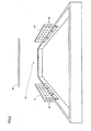
- FIG. 2 is a perspective view illustrating the appearance of the first support section 28 and the second support section 30 secured along the upper edge of the prize guiding space 22.
- the first support section 28 and the second support section 30 have a rectangular plate-like shape.
- Twenty-one (three rows and seven columns) holes 38 are arranged in a matrix in one side of each of the first support section 28 and the second support section 30.
- Each hole 38 has a diameter (e.g., 1.1 cm) that is larger to some extent than the diameter of the rod-like member 26 so that one rod-like member 26 can be inserted into each hole 38.
- the first support section 28 and the second support section 30 are respectively secured along the upper right edge and the upper left edge of the prize guiding space 22 so that the side of the first support section 28 in which the holes 38 are formed is opposite to the side of the second support section 30 in which the holes 38 are formed, and the first support section 28 is parallel to the second support section 30.
- the holes 38 are formed in the first support section 28 and the second support section 30 so that the holes 38 formed in the first support section 28 and the holes 38 formed in the second support section 30 are plane-symmetrical (mirror-symmetrical).
- a manager e.g., a clerk of a store in which the prize game apparatus 10 according to this embodiment is installed
- a manager can laterally dispose the rod-like member 26 at an arbitrary position over the prize guiding space 22 by inserting the right end of the rod-like member 26 into an arbitrary hole 38 formed in the first support section 28 and then inserting the left end of the rod-like member 26 into an arbitrary hole 38 formed in the second support section 30.
- the first support section 28 and the second support section 30 support the rod-like member 26 so that the support position where the first support section 28 supports the rod-like member 26 and the support position where the second support section 30 supports the rod-like member 26 can be changed, the position of the rod-like member 26 over the prize guiding space 22 can be changed.
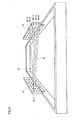
- FIG. 3 is a perspective view illustrating the internal structure of the first support section 28.
- a first contact section 40 that comes in contact with the end of the rod-like member 26 inserted into the hole 38 is provided inside the first support section 28 at a position corresponding to the holes 38.
- Each first contact section 40 is provided corresponding to laterally-arranged seven holes 38.
- a columnar guide 42 that extends along the direction in which the rod-like member 26 advances is provided inside the first support section 28.
- the guide 42 passes through the first contact section 40 on each end of the first contact section 40 in the longitudinal direction so that the first contact section 40 can reciprocate along the direction in which the rod-like member 26 advances.
- a compression spring 44 is provided around the guide 42. When the rod-like member 26 has been inserted into the hole 38 and the first contact section 40 has been moved away from the hole 38, the compression spring 44 applies a force that pushes the rod-like member 26 back.
- FIGS. 4A to 4C are cross-sectional views illustrating the internal structure of the first support section 28 and the second support section 30 when installing the rod-like member 26.
- the length of the rod-like member 26 in the longitudinal direction is larger than the distance between the opposing sides (i.e. the sides in which the holes 38 are formed) of the first support section 28 and the second support section 30.
- the manager can insert the right end of the rod-like member 26 into an arbitrary hole 38 formed in the first support section 28 by tilting the rod-like member 26 with respect to the horizontal direction.
- the first contact section 40 moves in the direction in which the rod-like member 26 advances while the compression spring 44 applies a force that pushes the rod-like member 26 back, as illustrated in FIG. 4B .
- a second contact section 46 that comes in contact with the left end of the rod-like member 26 inserted into the hole 38 is secured inside the second support section 30 (on the left in the drawings) at a position corresponding to the holes 38.
- the left end of the rod-like member 26 reaches the second contact section 46 in a state in which the compression spring 44 provided in the first contact section 40 is compressed (i.e., the elastic energy is stored).
- the rod-like member 26 of which the right end is inserted into the hole 38 formed in the first support section 28 and the left end is inserted into the hole 38 formed in the second support section 30 is stably supported, since the first contact section 40 presses the rod-like member 26 against the second contact section 46.
- the prize game apparatus 10 allows the manager to easily install the rod-like member 26 in the first support section 28 and the second support section 30 by inserting the right end of the rod-like member 26 into an arbitrary hole 38 formed in the first support section 28 and then inserting the left end of the rod-like member 26 into the corresponding hole 38 formed in the second support section 30.
- the rod-like member 26 can be removed from the first support section 28 and the second support section 30 by performing the above-described process in reverse order.
- FIG. 5 is a perspective view illustrating the appearance of the first support section 28 and the second support section 30 when inserting the rod-like member 26 into holes 38 having different positions.
- the length of the rod-like member 26 is sufficiently larger than the distance between the opposing sides (i.e. the sides in which the holes 38 are formed) of the first support section 28 and the second support section 30.
- the length of the rod-like member 26 is larger than the distance between a hole 38-31 in the third row and the first column of the first support section 28 and a hole 38-11 in the first row and the first column of the second support section 30, for example.
- the holes 38 formed in the first and second support sections 28, 30 are configured so that the rod-like member 26 can be inserted into the holes 38 perpendicularly to the first support section 28 and the second support section 30 (when the rod-like member 26 is lateral to the installation surface), and the rod-like member 26 can also be inserted into the holes 38 at a predetermined angle with respect to the direction perpendicular to the first support section 28 and the second support section 30 (when the rod-like member 26 is lateral to the installation surface in a tilted state).
- the moving range of the first contact section 40 inside the first support section 28 is specified so that the left end of the rod-like member 26 can be inserted into the hole 38 formed in the second support section 30 in a state in which the right end of the rod-like member 26 is inserted into the hole 38 formed in the first support section 28 even when the rod-like member 26 is inserted into the opposing holes 38 positioned at the shortest distance.
- the first support section 28 and the second support section 30 can support the rod-like member 26 perpendicularly inserted into the opposing holes 38 positioned at the shortest distance, and can also support the rod-like member 26 inserted in the hole 38-21 in the second row and the first column of the first support section 28 and the hole 38-11 in the first row and the first column of the second support section 30 or the hole 38-31 in the third row and the first column of the first support section 28 and the hole 38-11 in the first row and the first column of the second support section 30 in a tilted state, for example.
- the other end of the rod-like member 26 can be inserted in a tilted state into the hole 38 that is a hole of the other of the support sections but is not right opposite to the former hole 38 and is moved a little in upward or downward direction.
- the first support section 28 and the second support section 30 can support the rod-like member 26 in a tilted state.
- the first support section 28 and the second support section 30 can support the rod-like member 26 in a tilted state via the hole 38-14 in the first row and the fourth column of the first support section 28 and the hole 38-11 in the first row and the first column of the second support section 30, or the hole 38-23 in the second row and the third column of the first support section 28 and the hole 38-11 in the first row and the first column of the second support section 30.
- the position of the rod-like member 26 over the prize guiding space 22 can be changed while changing the arrangement angle of the rod-like member 26.
- FIG. 6 is an assembly diagram illustrating a frame section 48 that defines the upper edge of the prize guiding space 22, the first support section 28, and the second support section 30. As illustrated in FIG. 6 , the upper edge of the prize guiding space 22 is defined by the frame section 48 in the shape of a square. A plate-like member 50 protrudes downward from the lower end of the first support section 28 and the second support section 30. The plate-like member 50 has two threaded holes 52.
- the first support section 28 and the second support section 30 are secured at predetermined positions along the upper edge of the prize guiding space 22 by tightening a screw 54 into each threaded hole 52 so that the positions of the threaded holes 52 formed in the plate-like member 50 coincide with the positions (i.e., installation positions) of the threaded holes 52 formed in the inner circumferential surface of the frame section 48.
- the screws 54 used to secure the first support section 28 and the second support section 30 are finger screws having a head diameter of about 1 cm. Therefore, the manager can tighten or untighten the screw 54 into or from the threaded hole 52 without using a tool.
- each of the first support section 28 and the second support section 30 is smaller than one-third of the length of one side of the inner circumference of the frame section 48.
- Three pairs of threaded holes 52 are formed along each side of the frame section 48 (i.e., twelve pairs of threaded holes 52 are formed in the inner circumferential surface of the frame section 48).
- the installation positions of the first support section 28 and the second support section 30 are provided at twelve locations on the inner circumferential surface of the frame section 48.
- Each pair of threaded holes 52 is provided so that the installation positions on the opposing sides of the frame section 48 are plane-symmetrical.
- the rod-like member 26 can be disposed in the lateral direction in the front area over the prize guiding space 22, for example.
- the rod-like member 26 can be disposed in the front-rear direction in the center area over the prize guiding space 22.
- the prize game apparatus 10 allows the manager to secure the first support section 28 at an arbitrary installation position and secure the second support section 30 at an installation position opposite to the installation position of the first support section 28. Therefore, the position of the rod-like member 26 over the prize guiding space 22 can be changed by changing the installation positions of the first support section 28 and the second support section 30 along the upper edge of the prize guiding space 22.
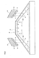
- FIG. 8 is an assembly diagram illustrating a prize placement section 56 on which a prize is placed, the frame section 48, the first support section 28, and the second support section 30.
- the prize placement section 56 having a rectangular plate-like shape can be disposed on the frame section 48 that defines the upper edge of the prize guiding space 22, as illustrated in FIG. 8 .
- An area in which the prize placement section 56 is placed can also function as the prize placement area 16. Therefore, a horizontal placement surface 58 having a width of about 1 cm is provided inwardly from the lower end of the inner circumferential surface of the frame section 48. The placement surface 58 allows the prize placement section 56 to be disposed at an arbitrary position over the prize guiding space 22.
- the prize placement section 56 is formed in the shape of a rectangle of which the long side has a length almost equal to that of one side of the inner circumference of the frame section 48 and the short side has a length about one-third of the length of one side of the inner circumference of the frame section 48. Therefore, when the prize placement section 56 is disposed on the placement surface 58 so that the side of the prize placement section 56 is parallel to the side of the frame section 48, one-third of the area over the prize guiding space 22 can function as the prize placement area 16.
- Threaded holes 52 used to secure the first support section 28 and the second support section 30 are formed in the side surface (i.e., outer circumferential surface) of the prize placement section 56 in the same manner as the inner circumferential surface of the frame section 48.
- the prize placement section 56 according to the example shown in FIG. 8 , three pairs of threaded holes 52 are formed along each of the long sides of the prize placement section 56 (i.e., six pairs of threaded holes 52 are formed in the side surfaces of the prize placement section 56).
- the installation positions of the first support section 28 and the second support section 30 are provided at six locations on the side surfaces of the prize placement section 56.
- the prize placement section 56 when the prize placement section 56 is disposed at the center of the front side of the frame section 48 and the center of the rear side of the frame section 48, as illustrated in FIG. 9 , for example, the prize placement section 56 can be disposed at the center over the prize guiding space 22 in the front-rear direction.
- the first support section 28 can be secured at the center of the right side of the prize placement section 56
- the second support section 30 can be secured at the center of the left side of the prize placement section 56.
- the distance between the first support section 28 and the second support section 30 corresponds to the length of the short side of the prize placement section 56 (i.e., about one-third of the length of one side of the inner circumference of the frame section 48).
- a plurality of rod-like members 26 that differ in length are provided corresponding to the installation positions of the first support section 28 and the second support section 30.
- the rod-like member 26 can be installed in the first support section 28 and the second support section 30 using the shortest rod-like member 26 that is formed to have a length about one-third of the length of one side of the inner circumference of the frame section 48.
- the rod-like member 26 can be installed in the first support section 28 and the second support section 30 even if the distance between the first support section 28 and the second support section 30 changes.
- the rod-like member 26 can be laterally disposed in the center area over the prize guiding space 22, as illustrated in FIG. 9 .
- the rod-like member 26 can be installed in the first support section 28 and the second support section 30 using the rod-like member 26 that is formed to have a length about two-thirds of the length of one side of the inner circumference of the frame section 48.
- the rod-like member 26 can be laterally disposed in the right front two-thirds area over the prize guiding space 22.
- the prize game apparatus 10 allows the manager to dispose the rod-like member 26 at an arbitrary position by securing the first support section 28 at an arbitrary installation position on the frame section 48 or the prize placement section 56, and securing the second support section 30 at an installation position on the frame section 48 or the prize placement section 56 corresponding to the installation position of the first support section 28.
- the position of the rod-like member 26 over the prize guiding space 22 can be changed by changing the installation positions of the first support section 28 and the second support section 30 along the outer circumferential surface of the prize placement section 56.
- the prize placement section 56 can be disposed over the prize guiding space 22 by disposing the prize placement section 56 on the placement surface 58 of the frame section 48. Note that the prize placement section 56 can also be disposed over the prize guiding space 22 by securing the prize placement section 56 on the rod-like members 26 that are disposed in various patterns. Therefore, the prize placement area 16 of the prize game apparatus 10 can be formed in various patterns over the prize guiding space 22.
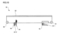
- FIG. 10 is a side view illustrating the side surface of the prize placement section 56 shown in FIG. 8 along the short side.
- the prize placement section 56 includes a prize placement surface 60 on which a prize is placed, a first attachment section 62 used to secure the prize placement section 56 on a first rod-like member 26-1, a second attachment section 64 used to secure the prize placement section 56 on a second rod-like member 26-2, and a securing section 66, the first attachment section 62, the second attachment section 64, and the securing section 66 being provided on the surface of the prize placement section 56 opposite to the prize placement surface 60.
- the first attachment section 62 is provided on one side of the center of gravity of the prize placement section 56.
- the first attachment section 62 receives the first rod-like member 26-1 from a lateral direction (i.e., the direction along the prize placement surface), and limits upward and downward movement of the prize placement section 56 with respect to the first rod-like member 26-1 at different positions in a lateral direction.
- FIG. 11 is a perspective view illustrating the appearance of the first attachment section 62. As illustrated in FIG. 11 , the first attachment section 62 is formed by bending a metal sheet having a thickness of about 1 mm so that the first rod-like member 26-1 can be received.
- the first attachment section 62 includes a first lower plate 68 that is provided parallel to the prize placement surface 60 and comes in line-contact with the lower part of the rod-like member 26 when the first attachment section 62 has received the rod-like member 26, a rear plate 70 that vertically extends upward from the rear end of the first lower plate 68, and a first upper plate 72 that vertically extends forward from the upper side of the rear plate 70 and comes in point-contact with the upper part of the first rod-like member 26-1 at two points.
- the first attachment section 62 thus forms a first space 74 that is parallel to the prize placement surface 60 and is surrounded by the first lower plate 68, the rear plate 70, and the first upper plate 72, the first space 74 having a height corresponding to the diameter of the rod-like member 26 and a depth corresponding to the total diameter of a plurality of rod-like members 26.
- an opening is formed between the front end of the first upper plate 72 and the front end of the first lower plate 68 so that the front end of the first space 74 forms a first open end 76. Since the right side and the left side of the first space 74 are open, the first attachment section 62 can receive the first rod-like member 26-1 that extends in a lateral direction in FIG.
- the first attachment section 62 When the first attachment section 62 has received the first rod-like member 26-1, the first attachment section 62 allows lateral movement of the prize placement section 56 while limiting upward and downward movement of the prize placement section 56 with respect to the first rod-like member 26-1.
- the second attachment section 64 is provided on the other side of the center of gravity of the prize placement section 56.
- the second attachment section 64 receives the second rod-like member 26-2 from below, and limits downward and lateral movement of the prize placement section 56 with respect to the second rod-like member 26-2.
- the securing section 66 is provided in the second attachment section 64. The securing section 66 limits upward movement of the prize placement section 56 with respect to the second rod-like member 26-2 after the second attachment section 64 has received the second rod-like member 26-2.
- FIG. 12 is a perspective view illustrating the appearance of the second attachment section 64 and the securing section 66.
- the second attachment section 64 is a tabular member that includes a tabular plate 78 provided perpendicularly to the prize placement surface 60, and a bent plate 80 that is bent to be able to receive the second rod-like member 26-2.
- the upper half of the tabular plate 78 and the upper half of the bent plate 80 are connected via a screw 54 that is screwed into a threaded hole 52.
- the threaded hole 52 and the screw 54 provided in the second attachment section 64 are identical to the threaded hole 52 and the screw 54 used to secure the first support section 28 and the second support section 30.
- the upper half of the tabular plate 78 comes in surface-contact with the upper half of the bent plate 80, and the lower half of the tabular plate 78 comes in line-contact with the rear side of the second rod-like member 26-2 when the second attachment section 64 has received the second rod-like member 26-2.
- the bent plate 80 is formed by bending a metal sheet having a thickness of about 1 mm, and includes a connection plate 82 that comes in surface-contact with the upper half of the tabular plate 78 and is connected to the tabular plate 78 via the screw 54, a second upper plate 84 that vertically extends forward from the lower end of the connection plate 82 and comes in line-contact with the upper part of the second rod-like member 26-2 when the second attachment section 64 has received the second rod-like member 26-2, a front plate 86 that vertically extends downward from the front end of the second upper plate 84 (extends parallel to the lower half of the tabular plate 78) and comes in line-contact with the front side of the second rod-like member 26-2, and a second lower plate 88 that obliquely extends from the lower end of the front plate 86 in the direction that approaches the lower half of the tabular plate 78 and comes in line-contact with the lower side of the second rod-like member 26-2.
- the second attachment section 64 thus forms a second space 90 that corresponds to the cross-sectional area of one rod-like member 26 and is surrounded by the lower half of the tabular plate 78, the second upper plate 84, the front plate 86, and the second lower plate 88.
- an opening is formed between the end of the second lower plate 88 and the lower end of the lower half of the tabular plate 78 so that the lower end of the second space 90 forms a second open end 92.
- the second attachment section 64 is formed so that the tabular plate 78 and the bent plate 80 are positioned (connected) at an interval, and the width (e.g., 1.2 cm) of the second open end 92 (i.e., the distance between the end of the second lower plate 88 and the lower end of the lower half of the tabular plate 78) is larger than the diameter (e.g., 1.0 cm) of the rod-like member 26 when the screw 54 is not tightened (non-secured state). Since the right side and the left side of the second space 90 are open, the second attachment section 64 can receive the second rod-like member 26-2 that extends in a lateral direction in FIG. 12 in the second space 90 from below.
- the second attachment section 64 is formed so that the tabular plate 78 and the bent plate 80 are closely connected and the width (e.g., 0.7 cm) of the second open end 92 is smaller than the diameter (e.g., 1.0 cm) of the rod-like member 26 when the screw 54 is tightened after the second attachment section 64 has received the second rod-like member 26-2.
- the second attachment section 64 limits upward, downward and lateral movement of the prize placement section 56 since the lower half of the tabular plate 78, the second upper plate 84, the front plate 86, and the second lower plate 88 adhere to the rear side, the upper part, the front side, and the lower part of the second rod-like member 26-2.
- the second lower plate 88 functions as the securing section 66 that limits upward movement of the prize placement section 56 with respect to the second rod-like member 26-2 when the screw 54 has been tightened (secured state).
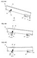
- FIGS. 13A to 13C are side views illustrating a process wherein the manager secures the prize placement section 56 on the first rod-like member 26-1 and the second rod-like member 26-2.
- the first rod-like member 26-1 and the second rod-like member 26-2 are disposed to be parallel to each other.
- the manager moves the prize placement section 56 so that the first rod-like member 26-1 is received by the first space 74 through the first open end 76 to attach the first attachment section 62 to the first rod-like member 26-1.
- the manager untightens the screw 54 (non-secured state), and rotates the prize placement section 56 so that the second rod-like member 26-2 is received by the second space 90 through the second open end 92 in a state in which the first attachment section 62 is attached to the first rod-like member 26-1 to attach the second attachment section 64 to the second rod-like member 26-2.
- the manager rotates the prize placement section 56 while moving the prize placement section 56 in a lateral direction (i.e., a direction along the prize placement surface 60) so that the position of the second attachment section 64 coincides with the position of the second rod-like member 26-2.
- the manager when the manager has attached the second attachment section 64 to the second rod-like member 26-2, the manager tightens the screw 54 of the second attachment section 64 to secure the second attachment section 64 on the second rod-like member 26-2. Specifically, the manager causes the second lower plate 88 to function as the securing section 66 by tightening the screw 54 of the second attachment section 64 (secured state).
- the prize placement section 56 can thus be stably secured on the first rod-like member 26-1 and the second rod-like member 26-2 by utilizing the first attachment section 62, the second attachment section 64, and the securing section 66. This prevents a situation in which the prize placement section 56 is removed from the first rod-like member 26-1 and the second rod-like member 26-2 even if the prize holding section 12 shown in FIG. 1 holds the prize placement section 56 when performing the hold operation on the end of the prize placement section 56, for example.
- the prize placement section 56 can be easily removed from the first rod-like member 26-1 and the second rod-like member 26-2 by performing the above-described process in reverse order.
- the prize placement section 56 includes a cylindrical roller 94 that is provided on each side of the back surface of the prize placement surface 60 and rotates around an axis along each side.
- a situation in which the arm section 36 of the prize holding section 12 is caught by the prize placement section 56 can be prevented due to rotation of the roller 94 even if the prize holding section 12 holds the prize placement section 56 when performing the hold operation on the end of the prize placement section 56. Therefore, a situation in which the prize holding section 12 is removed from the first rod-like member 26-1 and the second rod-like member 26-2 or the prize holding section 12 breaks when the prize holding section 12 holds the prize placement section 56 can be prevented.
- FIGS. 14A to 14C are side views illustrating the installation pattern of the prize placement section 56 when the positional relationship between the first rod-like member 26-1 and the second rod-like member 26-2 is changed.
- the first rod-like member 26-1 is inserted into the holes 38-11 in the first row and the first column of the first support section 28 and the second support section 30, and the second rod-like member 26-2 is inserted into the holes 38-17 in the first row and the seventh column of the first support section 28 and the second support section 30.
- the first rod-like member 26-1 comes in contact with the rear plate 70 at the deepest position inside the first space 74.
- the distance between the first rod-like member 26-1 and the second rod-like member 26-2 in FIG. 14A is the shortest distance that allows the first attachment section 62 to be secured on the first rod-like member 26-1 and the second attachment section 64 to be secured on the second rod-like member 26-2.
- the positions of the first rod-like member 26-1 and the second rod-like member 26-2 are changed by inserting the first rod-like member 26-1 and the second rod-like member 26-2 into arbitrary holes 38 formed in the first support section 28 and the second support section 30, as described above.
- the first rod-like member 26-1 is inserted into the holes 38-11 in the first row and the first column of the first support section 28 and the second support section 30, and the second rod-like member 26-2 is inserted into the holes 38-27 in the second row and the seventh column of the first support section 28 and the second support section 30.
- the distance between the first rod-like member 26-1 and the second rod-like member 26-2 shown in FIG. 14B is shorter than that shown in FIG.
- the first rod-like member 26-1 is positioned at the center of the first space 74.
- the first rod-like member 26-1 is inserted into the holes 38-11 in the first row and the first column of the first support section 28 and the second support section 30, and the second rod-like member 26-2 is inserted into the holes 38-36 in the third row and the sixth column of the first support section 28 and the second support section 30.
- the difference in height between the first rod-like member 26-1 and the second rod-like member 26-2 shown in FIG. 14C is larger than that shown in FIG. 14B , but the distance between the first rod-like member 26-1 and the second rod-like member 26-2 shown in FIG. 14C is shorter to some extent than that shown in FIG. 14B .
- the first rod-like member 26-1 is positioned closer to the rear plate 70 to some extent than the center of the first space 74.
- the first attachment section 62 and the second attachment section 64 are provided at fixed positions, since the first attachment section 62 is formed so that the depth of the first space 74 (i.e., the dimension in the direction along the prize placement surface 60) corresponds to the total diameter of a plurality of rod-like members 26, the first attachment section 62 can be secured on the first rod-like member 26-1 and the second attachment section 64 can be secured on the second rod-like member 26-2 even if the positional relationship between the first rod-like member 26-1 and the second rod-like member 26-2 is changed. Specifically, the first attachment section 62 limits upward and downward movement of the prize placement section 56 with respect to the first rod-like member 26-1 at different positions in a lateral direction (i.e., the direction along the prize placement surface 60).
- the prize placement section 56 can be secured to the first rod-like member 26-1 and the second rod-like member 26-2 not only horizontally but also in a tilted state as illustrated in FIGS. 14B and 14C .
- the prize placement section 56 can be stably disposed in various patterns over the prize guiding space 22.
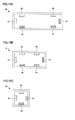
- FIGS. 15A to 15C are plan views illustrating the appearance of the back surface of the prize placement section 56.
- the prize placement section 56 shown in FIG. 15A is the same as the prize placement section 56 shown in FIG. 8 .
- the prize placement section 56 shown in FIG. 15A is formed in the shape of a rectangle so that the long side has a length almost the same as that of one side of the inner circumference of the frame section 48 shown in FIG. 8 and the short side has a length about one-third of the length of one side of the inner circumference of the frame section 48.
- the first attachment section 62 and the second attachment section 64 that make a pair are provided on the right side of the back surface of the prize placement section 56 so that the first attachment section 62 and the second attachment section 64 are opposite to each other in the direction along the short side.
- the first attachment section 62 and the second attachment section 64 that make a pair are provided on the left side of the back surface of the prize placement section 56 so that the first attachment section 62 and the second attachment section 64 are opposite to each other in the direction along the short side. Therefore, the prize placement section 56 can be secured on the first rod-like member 26-1 and the second rod-like member 26-2 at four locations.
- the first attachment section 62 and the second attachment section 64 that make a pair are also provided on the back surface of the prize placement section 56 so that the first attachment section 62 and the second attachment section 64 are opposite to each other in the direction along the long side. Therefore, the prize placement section 56 can be secured on the first rod-like member 26-1 and the second rod-like member 26-2 while changing the direction of the prize placement section 56 with respect to the first rod-like member 26-1 and the second rod-like member 26-2.
- a plurality of prize placement sections 56 that differ in shape and size are provided in addition to the prize placement section 56 shown in FIG. 15A .
- the prize placement section 56 shown in FIG. 15B is formed in the shape of a rectangle so that the long side has a length about two-thirds of the length of one side of the inner circumference of the frame section 48 shown in FIG. 8 and the short side has a length about one-third of the length of one side of the inner circumference of the frame section 48.
- the first attachment section 62 and the second attachment section 64 that make a pair are provided on each of the right side and the left side of the back surface of the prize placement section 56 shown in FIG.
- first attachment section 62 and the second attachment section 64 are opposite to each other in the direction along the short side.
- the first attachment section 62 and the second attachment section 64 that make a pair are also provided on the back surface of the prize placement section 56 shown in FIG. 15B so that the first attachment section 62 and the second attachment section 64 are opposite to each other in the direction along the long side.
- the prize placement section 56 shown in FIG. 15C is formed in the shape of a square so that one side has a length about one-third of the length of one side of the inner circumference of the frame section 48 shown in FIG. 8 .
- the first attachment section 62 and the second attachment section 64 that make a pair are provided on the back surface of the prize placement section 56 shown in FIG. 15C so that the first attachment section 62 and the second attachment section 64 are opposite to each other in a vertical direction.
- the first attachment section 62 and the second attachment section 64 that make a pair are also provided on the back surface of the prize placement section 56 shown in FIG. 15C so that the first attachment section 62 and the second attachment section 64 are opposite to each other in a lateral direction.
- the prize placement area 16 can be formed in various patterns over the prize guiding space 22 by arbitrarily combining the positions and the directions of the three types of prize placement sections 56.
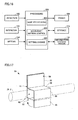
- FIG. 16 is a block diagram illustrating the functions of the prize game apparatus 10 according to this embodiment. Note that the prize game apparatus 10 according to this embodiment may have a configuration in which some of the elements (sections) shown in FIG. 16 are omitted.
- a detection section 100 detects the moving amount of the prize holding section 12 shown in FIG. 1 in the forward, backward, leftward, and rightward directions, and detects that the prize holding section 12 has moved downward and come in contact with a prize, the prize placement section 56, or the like.
- the detection section 100 may be implemented by a sensor.
- An operation section 102 allows the player to input operation information, and transmits the operation information to a processing section 200.
- the operation section 102 may be implemented by a button, a lever, and the like.
- a setting section 104 allows the manager to input setting information, and transmits the setting information to the processing section 200.
- the setting section 104 may be implemented by a button, a lever, and the like.
- Examples of the setting information include information that specifies an area of the game field 20 that is set to be the prize placement area 16, information that specifies an area set to be the open area 18, and the like. In this embodiment, information that indicates whether or not each area defined by dividing the game field 20 shown in FIG. 1 into nine areas in a matrix is the open area 18, is input to the setting section 104 as the setting information.
- a power section 106 is driven based on a control signal output from the processing section 200 to move the prize holding section 12 shown in FIG. 1 in the forward, backward, leftward, rightward, upward, and downward directions over the game field 20, and open or close the two arm sections 36 of the prize holding section 12.
- the power section 106 may be implemented by a motor.
- a storage section 108 serves as a work area for the processing section 200 and the like.
- the function of the storage section 108 may be implemented by hardware such as a RAM.
- An information storage medium 110 stores a program, data, and the like.
- the function of the information storage medium 110 may be implemented by an optical disk (CD or DVD), a magneto-optical disk (MO), a magnetic disk, a hard disk, a magnetic tape, a memory (ROM), or the like.
- the information storage medium 110 stores data and a program that causes the processing section 200 to perform various processes.
- the information storage medium 110 stores a program that causes a computer to function as each section according to this embodiment (i.e., a program that causes a computer to perform the process of each section).
- the processing section 200 (processor) performs a game process, a display control process, a sound generation process, and the like based on the data input from the detection section 100, the operation section 102, and the setting section 104, a program, and the like.
- the processing section 200 performs various processes using the storage section 108 as a work area.
- the function of the processing section 200 may be implemented by hardware such as a processor (e.g., CPU or DSP) or an integrated circuit (IC) (e.g., ASIC) and a program.
- the processing section 200 includes a game processing section 202, a movement/motion control section 204, and a setting change section 206. Note that the processing section 200 may have a configuration in which some of these sections are omitted.
- the game processing section 202 performs various game processes such as starting the game when game start conditions have been satisfied, proceeding with the game, or finishing the game when game finish conditions have been satisfied, based on data input from the detection section 100, the operation section 102, and the setting section 104, a program, and the like.
- the movement/motion control section 204 controls the movement/motion of the prize holding section 12 by controlling the power section 106 based on data input from the detection section 100, the operation section 102, and the setting section 104, a program, and the like.
- the movement/motion control section 204 causes the prize holding section 12 to perform the hold operation, and then causes the prize holding section 12 to automatically move to a position over the open area 18 based on information that indicates an area set to be the open area 18.
- the movement/motion control section 204 causes the prize holding section 12 to open the arm sections 36.
- the setting change section 206 changes values set in various types of information based on data input from the setting section 104, a program, and the like.
- the setting change section 206 changes a value that indicates an area set to be the open area 18 based on the setting information input using the setting section 104.
- the above embodiments have been described taking an example in which the prize guiding space 22 is open in the shape of a rectangle in a range corresponding to almost the entire area of the game field 20. Note that the open range and the shape of the prize guiding space 22 may be arbitrarily changed.
- first attachment section 62 and the second attachment section 64 are secured on the prize placement section 56 so that the prize placement section 56 is secured on the first rod-like member 26-1 and the second rod-like member 26-2 in a state in which the first rod-like member 26-1 and the second rod-like member 26-2 are provided in parallel.
- at least one of the first attachment section 62 and the second attachment section 64 may be provided so that its direction can be changed with respect to the prize placement surface 60.
- the prize placement section 56 can be secured on the first rod-like member 26-1 and the second rod-like member 26-2 even if the first rod-like member 26-1 and the second rod-like member 26-2 are not provided in parallel.
- At least one of the first attachment section 62 and the second attachment section 64 may be provided so that its position can be changed with respect to the prize placement surface 60.
- the position of at least one of the first attachment section 62 and the second attachment section 64 may be adjusted in the direction along the first rod-like member 26-1 and the second rod-like member 26-2 in a state in which the prize placement section 56 is secured on the first rod-like member 26-1 and the second rod-like member 26-2, or may be adjusted in the direction that intersects the first rod-like member 26-1 and the second rod-like member 26-2.
- the width of the second open end 92 of the second attachment section 64 increases when the screw 54 is not tightened to receive the rod-like member 26 in the second space 90, and the width of the second open end 92 decreases when the screw 54 is tightened so that the securing section 66 limits the upward movement of the prize placement section 56 with respect to the rod-like member 26.
- the securing section 66 may be provided in the second attachment section 64 so that the securing section 66 can be moved to open or close the second open end 92.
- the second attachment section 64 receives the second rod-like member 26-2 in the second space 90 in a state in which the securing section 66 opens the second open end 92, and the securing section 66 then closes the second open end 92 so that the securing section 66 limits the upward movement of the prize placement section 56 with respect to the rod-like member 26.
Landscapes
- Physics & Mathematics (AREA)
- General Physics & Mathematics (AREA)
- Pinball Game Machines (AREA)
- Coin-Freed Apparatuses For Hiring Articles (AREA)
- Toys (AREA)
Applications Claiming Priority (1)
| Application Number | Priority Date | Filing Date | Title |
|---|---|---|---|
| JP2008132414A JP2009279088A (ja) | 2008-05-20 | 2008-05-20 | 景品獲得ゲーム装置用の支持部、景品載置部および景品獲得ゲーム装置 |
Publications (2)
| Publication Number | Publication Date |
|---|---|
| EP2124203A1 true EP2124203A1 (fr) | 2009-11-25 |
| EP2124203B1 EP2124203B1 (fr) | 2011-01-19 |
Family
ID=40886426
Family Applications (1)
| Application Number | Title | Priority Date | Filing Date |
|---|---|---|---|
| EP09160534A Not-in-force EP2124203B1 (fr) | 2008-05-20 | 2009-05-18 | Section de support et section de placement de prix pour appareil de jeu de prix et appareil de jeu |
Country Status (4)
| Country | Link |
|---|---|
| EP (1) | EP2124203B1 (fr) |
| JP (1) | JP2009279088A (fr) |
| AT (1) | ATE496357T1 (fr) |
| DE (1) | DE602009000600D1 (fr) |
Families Citing this family (3)
| Publication number | Priority date | Publication date | Assignee | Title |
|---|---|---|---|---|
| JP5284021B2 (ja) * | 2008-09-17 | 2013-09-11 | 株式会社エンハート | 景品取得ゲーム装置 |
| JP2012254223A (ja) * | 2011-06-09 | 2012-12-27 | Sega Corp | 景品取得ゲーム機 |
| JP7064834B2 (ja) * | 2017-08-03 | 2022-05-11 | 株式会社マーベラス | ゲーム装置 |
Citations (1)
| Publication number | Priority date | Publication date | Assignee | Title |
|---|---|---|---|---|
| JP2005205169A (ja) | 2003-12-25 | 2005-08-04 | Namco Ltd | 景品獲得ゲーム装置 |
Family Cites Families (3)
| Publication number | Priority date | Publication date | Assignee | Title |
|---|---|---|---|---|
| JP3854874B2 (ja) * | 2002-02-08 | 2006-12-06 | サンデン株式会社 | ショーケースの商品棚 |
| JP4221388B2 (ja) * | 2005-03-28 | 2009-02-12 | 株式会社タイトー | 景品取得ゲーム機 |
| JP4177838B2 (ja) * | 2005-06-24 | 2008-11-05 | 株式会社タイトー | 景品払い出しゲーム機の景品押し出し装置 |
-
2008
- 2008-05-20 JP JP2008132414A patent/JP2009279088A/ja not_active Withdrawn
-
2009
- 2009-05-18 DE DE602009000600T patent/DE602009000600D1/de active Active
- 2009-05-18 EP EP09160534A patent/EP2124203B1/fr not_active Not-in-force
- 2009-05-18 AT AT09160534T patent/ATE496357T1/de not_active IP Right Cessation
Patent Citations (1)
| Publication number | Priority date | Publication date | Assignee | Title |
|---|---|---|---|---|
| JP2005205169A (ja) | 2003-12-25 | 2005-08-04 | Namco Ltd | 景品獲得ゲーム装置 |
Also Published As
| Publication number | Publication date |
|---|---|
| JP2009279088A (ja) | 2009-12-03 |
| EP2124203B1 (fr) | 2011-01-19 |
| ATE496357T1 (de) | 2011-02-15 |
| DE602009000600D1 (de) | 2011-03-03 |
Similar Documents
| Publication | Publication Date | Title |
|---|---|---|
| US9120008B2 (en) | Game apparatus | |
| US9216345B2 (en) | Prize placement section for prize game apparatus, and prize game apparatus | |
| EP2124203B1 (fr) | Section de support et section de placement de prix pour appareil de jeu de prix et appareil de jeu | |
| TW201020062A (en) | Automatic assembly fixture | |
| GB2451181A (en) | Prize grabber amusement machine | |
| JP2015093148A (ja) | 遊技機 | |
| JP2014184339A (ja) | 景品獲得ゲーム装置 | |
| US20050078445A1 (en) | Mounting apparatus for storage device | |
| JP5379273B2 (ja) | 景品獲得ゲーム装置用の景品載置部および景品獲得ゲーム装置 | |
| JP4570502B2 (ja) | スロットマシン | |
| JP2013255839A (ja) | 景品獲得ゲーム装置 | |
| JP2008183092A (ja) | 基板、基板の支持構造、及び同基板の支持構造を有する遊技機 | |
| JP4854689B2 (ja) | 引き出し形景品載置台によるクレーンゲーム機 | |
| JP2010188012A (ja) | 景品獲得ゲーム装置 | |
| JP3463060B2 (ja) | Vカッター用ピンキット | |
| JP6506563B2 (ja) | 遊技機 | |
| JP7409954B2 (ja) | 遊技機 | |
| JP5204443B2 (ja) | 遊技機 | |
| JP2005006839A (ja) | 遊技機用情報処理装置 | |
| CN1537738A (zh) | 内容可变的动态立体浮雕显示方法及装置 | |
| JP2009254895A (ja) | 遊技機用情報処理装置 | |
| CN201219024Y (zh) | 光盘快速上料架 | |
| JP3167513U (ja) | 景品獲得ゲーム装置 | |
| JP2004357921A (ja) | 遊技機 | |
| JP6622470B2 (ja) | 遊技機 |
Legal Events
| Date | Code | Title | Description |
|---|---|---|---|
| PUAI | Public reference made under article 153(3) epc to a published international application that has entered the european phase |
Free format text: ORIGINAL CODE: 0009012 |
|
| AK | Designated contracting states |
Kind code of ref document: A1 Designated state(s): AT BE BG CH CY CZ DE DK EE ES FI FR GB GR HR HU IE IS IT LI LT LU LV MC MK MT NL NO PL PT RO SE SI SK TR |
|
| 17P | Request for examination filed |
Effective date: 20100521 |
|
| GRAP | Despatch of communication of intention to grant a patent |
Free format text: ORIGINAL CODE: EPIDOSNIGR1 |
|
| GRAS | Grant fee paid |
Free format text: ORIGINAL CODE: EPIDOSNIGR3 |
|
| GRAA | (expected) grant |
Free format text: ORIGINAL CODE: 0009210 |
|
| AK | Designated contracting states |
Kind code of ref document: B1 Designated state(s): AT BE BG CH CY CZ DE DK EE ES FI FR GB GR HR HU IE IS IT LI LT LU LV MC MK MT NL NO PL PT RO SE SI SK TR |
|
| REG | Reference to a national code |
Ref country code: GB Ref legal event code: FG4D |
|
| REG | Reference to a national code |
Ref country code: CH Ref legal event code: EP |
|
| REG | Reference to a national code |
Ref country code: IE Ref legal event code: FG4D |
|
| REF | Corresponds to: |
Ref document number: 602009000600 Country of ref document: DE Date of ref document: 20110303 Kind code of ref document: P |
|
| REG | Reference to a national code |
Ref country code: DE Ref legal event code: R096 Ref document number: 602009000600 Country of ref document: DE Effective date: 20110303 |
|
| REG | Reference to a national code |
Ref country code: NL Ref legal event code: VDEP Effective date: 20110119 |
|
| LTIE | Lt: invalidation of european patent or patent extension |
Effective date: 20110119 |
|
| PG25 | Lapsed in a contracting state [announced via postgrant information from national office to epo] |
Ref country code: GR Free format text: LAPSE BECAUSE OF FAILURE TO SUBMIT A TRANSLATION OF THE DESCRIPTION OR TO PAY THE FEE WITHIN THE PRESCRIBED TIME-LIMIT Effective date: 20110420 Ref country code: LV Free format text: LAPSE BECAUSE OF FAILURE TO SUBMIT A TRANSLATION OF THE DESCRIPTION OR TO PAY THE FEE WITHIN THE PRESCRIBED TIME-LIMIT Effective date: 20110119 Ref country code: HR Free format text: LAPSE BECAUSE OF FAILURE TO SUBMIT A TRANSLATION OF THE DESCRIPTION OR TO PAY THE FEE WITHIN THE PRESCRIBED TIME-LIMIT Effective date: 20110119 Ref country code: ES Free format text: LAPSE BECAUSE OF FAILURE TO SUBMIT A TRANSLATION OF THE DESCRIPTION OR TO PAY THE FEE WITHIN THE PRESCRIBED TIME-LIMIT Effective date: 20110430 Ref country code: PT Free format text: LAPSE BECAUSE OF FAILURE TO SUBMIT A TRANSLATION OF THE DESCRIPTION OR TO PAY THE FEE WITHIN THE PRESCRIBED TIME-LIMIT Effective date: 20110519 Ref country code: NO Free format text: LAPSE BECAUSE OF FAILURE TO SUBMIT A TRANSLATION OF THE DESCRIPTION OR TO PAY THE FEE WITHIN THE PRESCRIBED TIME-LIMIT Effective date: 20110419 Ref country code: LT Free format text: LAPSE BECAUSE OF FAILURE TO SUBMIT A TRANSLATION OF THE DESCRIPTION OR TO PAY THE FEE WITHIN THE PRESCRIBED TIME-LIMIT Effective date: 20110119 Ref country code: SE Free format text: LAPSE BECAUSE OF FAILURE TO SUBMIT A TRANSLATION OF THE DESCRIPTION OR TO PAY THE FEE WITHIN THE PRESCRIBED TIME-LIMIT Effective date: 20110119 Ref country code: IS Free format text: LAPSE BECAUSE OF FAILURE TO SUBMIT A TRANSLATION OF THE DESCRIPTION OR TO PAY THE FEE WITHIN THE PRESCRIBED TIME-LIMIT Effective date: 20110519 |
|
| PG25 | Lapsed in a contracting state [announced via postgrant information from national office to epo] |
Ref country code: AT Free format text: LAPSE BECAUSE OF FAILURE TO SUBMIT A TRANSLATION OF THE DESCRIPTION OR TO PAY THE FEE WITHIN THE PRESCRIBED TIME-LIMIT Effective date: 20110119 Ref country code: NL Free format text: LAPSE BECAUSE OF FAILURE TO SUBMIT A TRANSLATION OF THE DESCRIPTION OR TO PAY THE FEE WITHIN THE PRESCRIBED TIME-LIMIT Effective date: 20110119 Ref country code: BG Free format text: LAPSE BECAUSE OF FAILURE TO SUBMIT A TRANSLATION OF THE DESCRIPTION OR TO PAY THE FEE WITHIN THE PRESCRIBED TIME-LIMIT Effective date: 20110419 Ref country code: BE Free format text: LAPSE BECAUSE OF FAILURE TO SUBMIT A TRANSLATION OF THE DESCRIPTION OR TO PAY THE FEE WITHIN THE PRESCRIBED TIME-LIMIT Effective date: 20110119 Ref country code: FI Free format text: LAPSE BECAUSE OF FAILURE TO SUBMIT A TRANSLATION OF THE DESCRIPTION OR TO PAY THE FEE WITHIN THE PRESCRIBED TIME-LIMIT Effective date: 20110119 Ref country code: CY Free format text: LAPSE BECAUSE OF FAILURE TO SUBMIT A TRANSLATION OF THE DESCRIPTION OR TO PAY THE FEE WITHIN THE PRESCRIBED TIME-LIMIT Effective date: 20110119 Ref country code: SI Free format text: LAPSE BECAUSE OF FAILURE TO SUBMIT A TRANSLATION OF THE DESCRIPTION OR TO PAY THE FEE WITHIN THE PRESCRIBED TIME-LIMIT Effective date: 20110119 Ref country code: PL Free format text: LAPSE BECAUSE OF FAILURE TO SUBMIT A TRANSLATION OF THE DESCRIPTION OR TO PAY THE FEE WITHIN THE PRESCRIBED TIME-LIMIT Effective date: 20110119 |
|
| PG25 | Lapsed in a contracting state [announced via postgrant information from national office to epo] |
Ref country code: EE Free format text: LAPSE BECAUSE OF FAILURE TO SUBMIT A TRANSLATION OF THE DESCRIPTION OR TO PAY THE FEE WITHIN THE PRESCRIBED TIME-LIMIT Effective date: 20110119 Ref country code: DK Free format text: LAPSE BECAUSE OF FAILURE TO SUBMIT A TRANSLATION OF THE DESCRIPTION OR TO PAY THE FEE WITHIN THE PRESCRIBED TIME-LIMIT Effective date: 20110119 |
|
| PLBE | No opposition filed within time limit |
Free format text: ORIGINAL CODE: 0009261 |
|
| STAA | Information on the status of an ep patent application or granted ep patent |
Free format text: STATUS: NO OPPOSITION FILED WITHIN TIME LIMIT |
|
| PG25 | Lapsed in a contracting state [announced via postgrant information from national office to epo] |
Ref country code: RO Free format text: LAPSE BECAUSE OF FAILURE TO SUBMIT A TRANSLATION OF THE DESCRIPTION OR TO PAY THE FEE WITHIN THE PRESCRIBED TIME-LIMIT Effective date: 20110119 Ref country code: SK Free format text: LAPSE BECAUSE OF FAILURE TO SUBMIT A TRANSLATION OF THE DESCRIPTION OR TO PAY THE FEE WITHIN THE PRESCRIBED TIME-LIMIT Effective date: 20110119 Ref country code: CZ Free format text: LAPSE BECAUSE OF FAILURE TO SUBMIT A TRANSLATION OF THE DESCRIPTION OR TO PAY THE FEE WITHIN THE PRESCRIBED TIME-LIMIT Effective date: 20110119 |
|
| 26N | No opposition filed |
Effective date: 20111020 |
|
| PG25 | Lapsed in a contracting state [announced via postgrant information from national office to epo] |
Ref country code: MC Free format text: LAPSE BECAUSE OF NON-PAYMENT OF DUE FEES Effective date: 20110531 Ref country code: IT Free format text: LAPSE BECAUSE OF FAILURE TO SUBMIT A TRANSLATION OF THE DESCRIPTION OR TO PAY THE FEE WITHIN THE PRESCRIBED TIME-LIMIT Effective date: 20110119 Ref country code: MT Free format text: LAPSE BECAUSE OF FAILURE TO SUBMIT A TRANSLATION OF THE DESCRIPTION OR TO PAY THE FEE WITHIN THE PRESCRIBED TIME-LIMIT Effective date: 20110119 |
|
| REG | Reference to a national code |
Ref country code: DE Ref legal event code: R097 Ref document number: 602009000600 Country of ref document: DE Effective date: 20111020 |
|
| REG | Reference to a national code |
Ref country code: FR Ref legal event code: ST Effective date: 20120131 |
|
| REG | Reference to a national code |
Ref country code: IE Ref legal event code: MM4A |
|
| REG | Reference to a national code |
Ref country code: DE Ref legal event code: R119 Ref document number: 602009000600 Country of ref document: DE Effective date: 20111201 |
|
| PG25 | Lapsed in a contracting state [announced via postgrant information from national office to epo] |
Ref country code: IE Free format text: LAPSE BECAUSE OF NON-PAYMENT OF DUE FEES Effective date: 20110518 Ref country code: FR Free format text: LAPSE BECAUSE OF NON-PAYMENT OF DUE FEES Effective date: 20110531 |
|
| REG | Reference to a national code |
Ref country code: AT Ref legal event code: MK05 Ref document number: 496357 Country of ref document: AT Kind code of ref document: T Effective date: 20110119 |
|
| PG25 | Lapsed in a contracting state [announced via postgrant information from national office to epo] |
Ref country code: MK Free format text: LAPSE BECAUSE OF FAILURE TO SUBMIT A TRANSLATION OF THE DESCRIPTION OR TO PAY THE FEE WITHIN THE PRESCRIBED TIME-LIMIT Effective date: 20110119 |
|
| PG25 | Lapsed in a contracting state [announced via postgrant information from national office to epo] |
Ref country code: LU Free format text: LAPSE BECAUSE OF NON-PAYMENT OF DUE FEES Effective date: 20110518 |
|
| PG25 | Lapsed in a contracting state [announced via postgrant information from national office to epo] |
Ref country code: DE Free format text: LAPSE BECAUSE OF NON-PAYMENT OF DUE FEES Effective date: 20111201 |
|
| PG25 | Lapsed in a contracting state [announced via postgrant information from national office to epo] |
Ref country code: TR Free format text: LAPSE BECAUSE OF FAILURE TO SUBMIT A TRANSLATION OF THE DESCRIPTION OR TO PAY THE FEE WITHIN THE PRESCRIBED TIME-LIMIT Effective date: 20110119 |
|
| PG25 | Lapsed in a contracting state [announced via postgrant information from national office to epo] |
Ref country code: HU Free format text: LAPSE BECAUSE OF FAILURE TO SUBMIT A TRANSLATION OF THE DESCRIPTION OR TO PAY THE FEE WITHIN THE PRESCRIBED TIME-LIMIT Effective date: 20110119 |
|
| REG | Reference to a national code |
Ref country code: CH Ref legal event code: PL |
|
| PG25 | Lapsed in a contracting state [announced via postgrant information from national office to epo] |
Ref country code: LI Free format text: LAPSE BECAUSE OF NON-PAYMENT OF DUE FEES Effective date: 20130531 Ref country code: CH Free format text: LAPSE BECAUSE OF NON-PAYMENT OF DUE FEES Effective date: 20130531 |
|
| REG | Reference to a national code |
Ref country code: GB Ref legal event code: 732E Free format text: REGISTERED BETWEEN 20220707 AND 20220713 |
|
| PGFP | Annual fee paid to national office [announced via postgrant information from national office to epo] |
Ref country code: GB Payment date: 20240402 Year of fee payment: 16 |
|
| REG | Reference to a national code |
Ref country code: GB Ref legal event code: 732E Free format text: REGISTERED BETWEEN 20250911 AND 20250917 |
|
| GBPC | Gb: european patent ceased through non-payment of renewal fee |
Effective date: 20250518 |
|
| PG25 | Lapsed in a contracting state [announced via postgrant information from national office to epo] |
Ref country code: GB Free format text: LAPSE BECAUSE OF NON-PAYMENT OF DUE FEES Effective date: 20250518 |