EP2124208A2 - Télécommande programmable et procédé de programmation d'une télécommande - Google Patents
Télécommande programmable et procédé de programmation d'une télécommande Download PDFInfo
- Publication number
- EP2124208A2 EP2124208A2 EP09005388A EP09005388A EP2124208A2 EP 2124208 A2 EP2124208 A2 EP 2124208A2 EP 09005388 A EP09005388 A EP 09005388A EP 09005388 A EP09005388 A EP 09005388A EP 2124208 A2 EP2124208 A2 EP 2124208A2
- Authority
- EP
- European Patent Office
- Prior art keywords
- code
- remote control
- key
- combinations
- combination
- Prior art date
- Legal status (The legal status is an assumption and is not a legal conclusion. Google has not performed a legal analysis and makes no representation as to the accuracy of the status listed.)
- Withdrawn
Links
- 238000000034 method Methods 0.000 title claims abstract description 10
- 230000006870 function Effects 0.000 claims description 47
- 230000004044 response Effects 0.000 claims description 4
- 238000012790 confirmation Methods 0.000 claims 1
- 230000001960 triggered effect Effects 0.000 claims 1
- 238000012795 verification Methods 0.000 claims 1
- 238000010586 diagram Methods 0.000 description 2
- FGRBYDKOBBBPOI-UHFFFAOYSA-N 10,10-dioxo-2-[4-(N-phenylanilino)phenyl]thioxanthen-9-one Chemical compound O=C1c2ccccc2S(=O)(=O)c2ccc(cc12)-c1ccc(cc1)N(c1ccccc1)c1ccccc1 FGRBYDKOBBBPOI-UHFFFAOYSA-N 0.000 description 1
- 230000001419 dependent effect Effects 0.000 description 1
- 238000011161 development Methods 0.000 description 1
- 230000018109 developmental process Effects 0.000 description 1
- 230000002349 favourable effect Effects 0.000 description 1
- 230000008520 organization Effects 0.000 description 1
Images
Classifications
-
- G—PHYSICS
- G08—SIGNALLING
- G08C—TRANSMISSION SYSTEMS FOR MEASURED VALUES, CONTROL OR SIMILAR SIGNALS
- G08C23/00—Non-electrical signal transmission systems, e.g. optical systems
- G08C23/04—Non-electrical signal transmission systems, e.g. optical systems using light waves, e.g. infrared
-
- G—PHYSICS
- G08—SIGNALLING
- G08C—TRANSMISSION SYSTEMS FOR MEASURED VALUES, CONTROL OR SIMILAR SIGNALS
- G08C19/00—Electric signal transmission systems
- G08C19/16—Electric signal transmission systems in which transmission is by pulses
- G08C19/28—Electric signal transmission systems in which transmission is by pulses using pulse code
-
- G—PHYSICS
- G08—SIGNALLING
- G08C—TRANSMISSION SYSTEMS FOR MEASURED VALUES, CONTROL OR SIMILAR SIGNALS
- G08C2201/00—Transmission systems of control signals via wireless link
- G08C2201/20—Binding and programming of remote control devices
-
- G—PHYSICS
- G08—SIGNALLING
- G08C—TRANSMISSION SYSTEMS FOR MEASURED VALUES, CONTROL OR SIMILAR SIGNALS
- G08C2201/00—Transmission systems of control signals via wireless link
- G08C2201/20—Binding and programming of remote control devices
- G08C2201/21—Programming remote control devices via third means
-
- G—PHYSICS
- G08—SIGNALLING
- G08C—TRANSMISSION SYSTEMS FOR MEASURED VALUES, CONTROL OR SIMILAR SIGNALS
- G08C2201/00—Transmission systems of control signals via wireless link
- G08C2201/90—Additional features
- G08C2201/92—Universal remote control
Definitions
- the invention relates to a programmable remote control according to the preamble of claims 1 and 7 and to a method for programming a remote control according to the preamble of claims 6 and 8.
- Remote controls and methods of this kind are from the US Pat. No. 4,626,848 known.
- a programmable universal remote control is proposed which receives, decodes and stores remote control codes transmitted from an original remote control so that the remote control to be programmed "learns" the corresponding codes of the original remote control.
- the programmable remote control is then functionally a copy of the original remote control.
- the remote-controlled device receives the code and triggers certain functions on it.
- the universal remote control successively sends various codes for the on / off function of devices. If the device then switches on or off accordingly, the other functions of the other buttons must then be checked, since the same code is used for the on / off function of many devices, but the codes for the other buttons are different. This method is therefore time consuming and tedious.
- the object of the invention is therefore to improve the known programmable remote control to the extent that their programming is much easier. This object is achieved by the features specified in the patent claims 1, 6, 7 and 8. Advantageous embodiments and further developments of the invention can be found in the dependent claims.
- the basic idea of the invention lies in the fact that in a first step the remote control to be programmed learns the code of only one specific key (eg the on / off key), then in a second step checks in a database which code combinations assigned this learned code to the corresponding key. These "matching" code combinations are then selected for further programming. In a possible further step, the user is prompted to read in another code of another key, which in turn is checked in the database, which code combinations have the two codes read in for the two key functions. It is particularly advantageous if, in this second and possibly further subsequent steps, that function is queried in which the previously selected code combinations differ from one another. Matching functions of the selected code combinations are thus skipped and not queried. This process is repeated until a unique "correct" code combination has been determined. Despite the enormous variety of code combinations available on the market, in practice the correct code combination is found after two to three learning steps.
- the database of all common code combinations can be stored on a memory chip in the universal remote control. It is also possible to keep the database on a PC and to provide the customer with all codes on a CD-Rom. Finally, it is also possible to query the database via the Internet.
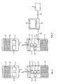
- FIG. 1 schematically shows a universal remote control 1 to be programmed, which is to learn the corresponding codes from an existing original remote control 2.
- the original remote control 2 has a plurality of keys 3, to each of which a specific code is assigned, which is emitted as a coded infrared signal via a transmitting diode 3.
- the entirety of all the keys assigned to the keys for an individual original remote control 2 is referred to as a code combination stored in a memory 4 of the original remote control.
- Via a microprocessor 7 ' the operation of the original remote control 2 is controlled.
- the universal remote control 1 to be programmed contains a receiving diode 5 of known design, a receiving and decoding unit 6, a microprocessor 7 and a memory 8 and a keyboard 10. In this respect, it is a conventional programmable Remote control.
- the receiving diode 5 can also be the transmitting diode used in the later use of the universal remote control 1, with the microprocessor 7 controlling the switching between transmitting and receiving operation.
- the programmable remote control 1 may also include a display 11 through which instructions or information can be presented to the user.
- a display instead of a display but can also be used with cheaper variants, a light emitting diode (LED), which gives corresponding signals by flashing. It is also possible to output acoustic signals.
- LED light emitting diode
- FIG. 2 is different from that of FIG. 1 essentially in that the database 9 is arranged externally, ie outside the remote control 1 to be programmed, and that the remote control 1 has an interface 12 via which the remote control 1 can be connected to a computer 13.
- This can be, for example, a USB interface via which the remote control 1 is connected to the computer 13 with a cable 14.
- the database 9 can then be stored in the computer 13 or queried via a CD-ROM from the computer 13.
- a part of the receiving and decoding unit 6 are moved into the computer 13, namely, for example, the decoding function and / or an analysis function.
- the receiving unit 6 then only has the task of converting the received infrared signal into a digitized bit stream, which is sent under control of the microprocessor 7 via the interface 12 to the computer 13 where it is analyzed and decoded.
- This function can also be moved via the Internet to an external area, such as the manufacturer.
- the analysis is, in principle, that from characteristics of the bit stream, e.g. Carrier frequency, times between different frames is detected, which infrared system it is, from which then the actual "code” is extracted as a digitized beamer signal.
- characteristics of the bit stream e.g. Carrier frequency
- the database 9 can also be stored externally at a manufacturer and be queried by the computer 13 via an Internet connection 16.
- the programming of the remote control 1 is as follows: The remote control 1 is set by a switch or by pressing a specific key combination in the operating state "program”. Then the user is prompted, for example via the display 11, to press a predetermined key on the original remote control 2 and thereby trigger a predetermined function. This can be, for example, the on / off function.
- the original remote control 2 then sends via the transmitter diode 3 a corresponding coded Infrared signal which is received by the receiving diode 5 of the remote control 1 and is supplied to the microprocessor 7 after decoding in the receiver / decoder 6 as a digital signal.
- the microprocessor 7 checks whether there are stored in the database 9 one or more code combinations in which the previously received code is assigned to the corresponding function.
- the universal remote control 1 can be set to the normal operating mode either automatically or by pressing a predetermined key combination.
- the sequence of programming in the embodiment of FIG. 2 takes place in an analogous manner by the external database 9 is queried via the interface 12 and the computer 13. If the appropriate code combination in the database 9 is determined in this way, it is written into the memory 8 and the interface 12 can be disconnected.
- the sequence control can in the embodiment of FIG. 2 be done by the computer 13 by a corresponding program is stored, instructions for the steps to be taken can also be displayed on a screen 15 of the computer 13.
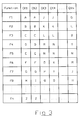
- FIG. 3 schematically shows the organization of the database 9.
- Each by a button of the remote control 1 retrievable Function F1 to Fn are assigned certain codes, which are designated here by letters A to Z. Of course, these are digital codes with bit sequences that represent logical 1 or logical 0.
- a large number of different code combinations CK1, CK2 to CKn is stored.
- the function F1 in the code combinations CK1 and CK2 is occupied by the code A, in the code combinations CK3 and CK4 by the code J and in the code combination CKn by the code G.
- the function F2 is in the case of Code combinations CK1 and CK2 with the code B, with the code combinations CK3 and CK4 with the code K and with the code combination CKn with the code G, etc. It is further assumed that the code combination CK1 and CK2 are identical in terms of the codes for the functions F1 to F7 and differ only in the function F8.
- the function F1 is called and the original remote control 2 transmits the code A.
- the code combinations CK1 and CK2 are selected, while all other code combinations can be eliminated.
- the codes CK1 and CK2 are identical in the codes F1 to F7 and differ only in the function F8 and possibly other functions.
- the function is called in the next step, in which the codes of the code combinations CK1 and CK2 no longer match, ie in the embodiment of FIG. 3 the function F8.
- the matching functions F2 to F7 therefore need not be queried. If the user presses the key assigned to function F8, it will In this case, for example, the code H emitted, the code combination CK1 is uniquely identified, of course, on condition that all other functions F9 to Fn are again identical.
- the programming proceeds with respect to the code combinations CK3 and CK4. If the code J is recognized in the first function F1, the first non-matching function is called in the second step, that is to say in the exemplary embodiment of FIG FIG. 3 the function F6.
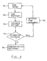
- FIG. 4 shows again in the form of a flow chart the steps.
- the first code is sent from the original remote control 2, received and decoded by the remote control 1 to be programmed in step S2.
- step S3 the database is queried and those code combinations are selected which have assigned the received code to the corresponding function.
- step S4 it is checked whether only a single code combination is contained in the database, in which the received code is assigned to the corresponding function. If this is the case, then in step S5 taken over the selected code combination and stored in the remote control 1 to be programmed. If the check in step S4 indicates that a plurality of code combinations are selected, the user is prompted in step S6 to press another predetermined key and the process moves on to step S1. The further predetermined key is followed by the selected code combinations determines the criterion that the codes of the corresponding function (or key) differ from each other. The loop thus formed is run through until the test in step S4 selects only a single code combination.
- the programmable remote control described so far and the method described assume that there is an original remote control with which the programmable remote control is programmed.
- the programmable remote control learns, so to speak, the right code combination from the original remote control.
- the stock of stored code combinations is substantially restricted and the further “trying out” of code combinations only becomes provided the limited number of code combinations.
- the code combinations CK1 and CK2 in the embodiment of FIG. 3 is identified, the user is prompted to press the F8 key and to check the response on the TV. If, for example, the code combination CK1 is initially selected and the code I is received when the function F8 is called, then no or an incorrect function is called up on the television set.
- the remote control switches to the next matching code combination, in this case the code combination CK2, and the user again presses the key for the function F8, whereupon the appropriate code I is sent.
- the user recognizes that the appropriate code has been received and thus the code combination CK2 has been uniquely identified.
- This variant can be analogous FIG. 1 with an internal database 9 or analog FIG. 2 with an external database.
- an infrared signal to an associated device such as a TV, sent and waits for its response to a corresponding signal and confirmed at the correct function by a button, then what for the next steps the stock of queried code combinations is restricted.
Landscapes
- Physics & Mathematics (AREA)
- General Physics & Mathematics (AREA)
- Selective Calling Equipment (AREA)
Applications Claiming Priority (1)
| Application Number | Priority Date | Filing Date | Title |
|---|---|---|---|
| DE102008024632A DE102008024632B4 (de) | 2008-05-21 | 2008-05-21 | Programmierbare Fernsteuerung und Verfahren zum Programmieren einer Fernsteuerung |
Publications (2)
| Publication Number | Publication Date |
|---|---|
| EP2124208A2 true EP2124208A2 (fr) | 2009-11-25 |
| EP2124208A3 EP2124208A3 (fr) | 2014-05-28 |
Family
ID=41052051
Family Applications (1)
| Application Number | Title | Priority Date | Filing Date |
|---|---|---|---|
| EP09005388.5A Withdrawn EP2124208A3 (fr) | 2008-05-21 | 2009-04-15 | Télécommande programmable et procédé de programmation d'une télécommande |
Country Status (4)
| Country | Link |
|---|---|
| US (1) | US20090289829A1 (fr) |
| EP (1) | EP2124208A3 (fr) |
| CA (1) | CA2665930A1 (fr) |
| DE (1) | DE102008024632B4 (fr) |
Families Citing this family (17)
| Publication number | Priority date | Publication date | Assignee | Title |
|---|---|---|---|---|
| US11769398B2 (en) | 2005-09-08 | 2023-09-26 | Universal Electronics Inc. | System and method for widget-assisted setup of a universal remote control |
| US7907222B2 (en) | 2005-09-08 | 2011-03-15 | Universal Electronics Inc. | System and method for simplified setup of a universal remote control |
| US9208679B2 (en) | 2006-09-05 | 2015-12-08 | Universal Electronics Inc. | System and method for configuring the remote control functionality of a portable device |
| US8812629B2 (en) | 2008-04-18 | 2014-08-19 | Universal Electronics Inc. | System and method for configuring the remote control functionality of a portable device |
| US8659400B2 (en) | 2006-09-05 | 2014-02-25 | Universal Electronics Inc. | System and method for configuring the remote control functionality of a portable device |
| US9088663B2 (en) | 2008-04-18 | 2015-07-21 | Universal Electronics Inc. | System for appliance control via a network |
| US9852615B2 (en) | 2011-03-25 | 2017-12-26 | Universal Electronics Inc. | System and method for facilitating appliance control via a smart device |
| US20120033975A1 (en) * | 2009-04-10 | 2012-02-09 | Young Kwan Yoon | Apparatus and method for motor rotation control with an ir receiver |
| US8410970B2 (en) * | 2009-08-13 | 2013-04-02 | At&T Intellectual Property I, L.P. | Programming a universal remote control via direct interaction |
| US8618917B2 (en) * | 2010-02-01 | 2013-12-31 | Echostar Technologies L.L.C. | Apparatus, systems and methods for remote control learning |
| JP2012023630A (ja) * | 2010-07-15 | 2012-02-02 | Funai Electric Co Ltd | 電気機器 |
| DE202011101824U1 (de) * | 2011-06-15 | 2011-09-30 | Sommer Antriebs- Und Funktechnik Gmbh | Handsender |
| US9019435B2 (en) | 2011-09-22 | 2015-04-28 | Universal Electronics Inc. | System and method for configuring controlling device functionality |
| US11756412B2 (en) | 2011-10-28 | 2023-09-12 | Universal Electronics Inc. | Systems and methods for associating services and/or devices with a voice assistant |
| US11295603B2 (en) | 2011-10-28 | 2022-04-05 | Universal Electronics Inc. | System and method for optimized appliance control |
| US9250087B2 (en) * | 2014-02-26 | 2016-02-02 | International Business Machines Corporation | Identification of mobile device location |
| DE102015108746B3 (de) * | 2015-06-02 | 2016-09-15 | Fm Marketing Gmbh | Verfahren zur Kopplung einer Fernbedienung und einem elektronischen Gerät |
Citations (1)
| Publication number | Priority date | Publication date | Assignee | Title |
|---|---|---|---|---|
| US4626848A (en) | 1984-05-15 | 1986-12-02 | General Electric Company | Programmable functions for reconfigurable remote control |
Family Cites Families (7)
| Publication number | Priority date | Publication date | Assignee | Title |
|---|---|---|---|---|
| DE3313493A1 (de) * | 1983-04-14 | 1984-10-18 | Telefunken Fernseh Und Rundfunk Gmbh, 3000 Hannover | Fernbedienungsgeraet zur drahtlosen steuerung verschiedener geraete |
| US5819294A (en) * | 1997-08-06 | 1998-10-06 | Philips Electronics North America Corporation | Automatic configuration mechanism for universal remote |
| US6236350B1 (en) * | 1997-09-05 | 2001-05-22 | Thomson Licensing S.A. | Universal remote control code identification system |
| US20010033243A1 (en) * | 2000-03-15 | 2001-10-25 | Harris Glen Mclean | Online remote control configuration system |
| US6774813B2 (en) * | 2001-03-30 | 2004-08-10 | Koninklijke Philips Electronics N.V. | System and method for interleaving infrared command codes with identifier codes |
| US7429932B1 (en) * | 2004-06-30 | 2008-09-30 | Microsoft Corporation | Remote control code set identification system |
| US7375673B2 (en) * | 2005-01-13 | 2008-05-20 | Netgear, Inc. | System and method for universal remote control configuration |
-
2008
- 2008-05-21 DE DE102008024632A patent/DE102008024632B4/de not_active Expired - Fee Related
-
2009
- 2009-04-15 EP EP09005388.5A patent/EP2124208A3/fr not_active Withdrawn
- 2009-05-13 CA CA002665930A patent/CA2665930A1/fr not_active Abandoned
- 2009-05-13 US US12/465,393 patent/US20090289829A1/en not_active Abandoned
Patent Citations (1)
| Publication number | Priority date | Publication date | Assignee | Title |
|---|---|---|---|---|
| US4626848A (en) | 1984-05-15 | 1986-12-02 | General Electric Company | Programmable functions for reconfigurable remote control |
Also Published As
| Publication number | Publication date |
|---|---|
| EP2124208A3 (fr) | 2014-05-28 |
| DE102008024632A1 (de) | 2009-12-10 |
| US20090289829A1 (en) | 2009-11-26 |
| CA2665930A1 (fr) | 2009-11-21 |
| DE102008024632B4 (de) | 2010-07-29 |
Similar Documents
| Publication | Publication Date | Title |
|---|---|---|
| DE102008024632B4 (de) | Programmierbare Fernsteuerung und Verfahren zum Programmieren einer Fernsteuerung | |
| EP2161696B1 (fr) | Agencement multimédia doté d'une télécommande universelle programmable et procédé de programmation d'une télécommande | |
| DE69837653T2 (de) | Automatische konfigurationseinrichtung für universale fernsteuerung | |
| DE68928562T2 (de) | Vorrichtung und verfahren zur verwendung von kodierten daten für die zeitvorprogrammierung eines videorecorders/videoabspielers | |
| DE69122104T2 (de) | Fernsteuerbares gerät | |
| DE3687717T2 (de) | Universelle fernsteueranordnung. | |
| DE69129659T2 (de) | System und methode zur fernüberwachung von kopiergeräten | |
| EP0756742B1 (fr) | Procede et dispositif de telecommande vocale de consommateurs electriques | |
| DE69620853T2 (de) | Vps kompatibles gerät und verfahren mit verwendung von komprimierten kodesignalen für die infrarotkode auswahl | |
| EP0122548B1 (fr) | Appareil de télécommande sans fil de différents dispositifs | |
| EP0780990A2 (fr) | Procédé et dipositif de commande à distance d'equipement électronique | |
| DE202013100036U1 (de) | Bildverarbeitungsvorrichtung und Bildverarbeitungssystem | |
| DE69909637T2 (de) | Verfahren zur speicherung eines kanales für ein gerät der unterhaltungselektronik | |
| DE68920458T2 (de) | Universeller Fernsteuerungs-Sender mit vereinfachter Apparatidentifizierung. | |
| DE102007060285A1 (de) | Computervorrichtung mit Tastatursperrfunktion sowie Verfahren zum Ausführen einer Tastatursperrung in der Computervorrichtung | |
| DE4025302C2 (fr) | ||
| DE3508562A1 (de) | Verfahren und anordnung zur uebertragung von informationen | |
| DE69122386T2 (de) | Rundfunkempfängersystem | |
| DE69712376T2 (de) | Fernbedientes codesuchverfahren und vorrichtung dazu | |
| DE69016897T2 (de) | Verbesserter Fernsehempfänger. | |
| DE19615827B4 (de) | Tastsensoren der Gebäudesystemtechnik mit verborgenen Bedienfunktionen | |
| EP0328773A2 (fr) | Transmetteur de télécommande avec lecteur de code à barres | |
| EP0467108B1 (fr) | Appareil récepteur de signal de télévision avec un dispositif de programmation à balayage | |
| DE69804816T2 (de) | Anpassbare fernbedienung für elektrische geräte mit mehreren zu steuerenden funktionen | |
| DE3438333A1 (de) | Sprachempfindliche vorrichtung |
Legal Events
| Date | Code | Title | Description |
|---|---|---|---|
| PUAI | Public reference made under article 153(3) epc to a published international application that has entered the european phase |
Free format text: ORIGINAL CODE: 0009012 |
|
| AK | Designated contracting states |
Kind code of ref document: A2 Designated state(s): AT BE BG CH CY CZ DE DK EE ES FI FR GB GR HR HU IE IS IT LI LT LU LV MC MK MT NL NO PL PT RO SE SI SK TR |
|
| PUAL | Search report despatched |
Free format text: ORIGINAL CODE: 0009013 |
|
| AK | Designated contracting states |
Kind code of ref document: A3 Designated state(s): AT BE BG CH CY CZ DE DK EE ES FI FR GB GR HR HU IE IS IT LI LT LU LV MC MK MT NL NO PL PT RO SE SI SK TR |
|
| AX | Request for extension of the european patent |
Extension state: AL BA RS |
|
| RIC1 | Information provided on ipc code assigned before grant |
Ipc: G08C 19/28 20060101AFI20140424BHEP |
|
| STAA | Information on the status of an ep patent application or granted ep patent |
Free format text: STATUS: THE APPLICATION IS DEEMED TO BE WITHDRAWN |
|
| 18D | Application deemed to be withdrawn |
Effective date: 20141129 |