EP2124287A2 - Vorrichtung mit Fenster zur Ansicht eines Kraftstoffmessgeräts auf einer Batterie - Google Patents
Vorrichtung mit Fenster zur Ansicht eines Kraftstoffmessgeräts auf einer Batterie Download PDFInfo
- Publication number
- EP2124287A2 EP2124287A2 EP09250115A EP09250115A EP2124287A2 EP 2124287 A2 EP2124287 A2 EP 2124287A2 EP 09250115 A EP09250115 A EP 09250115A EP 09250115 A EP09250115 A EP 09250115A EP 2124287 A2 EP2124287 A2 EP 2124287A2
- Authority
- EP
- European Patent Office
- Prior art keywords
- battery pack
- battery
- fuel gauge
- housing
- window
- Prior art date
- Legal status (The legal status is an assumption and is not a legal conclusion. Google has not performed a legal analysis and makes no representation as to the accuracy of the status listed.)
- Withdrawn
Links
Images


Classifications
-
- H—ELECTRICITY
- H01—ELECTRIC ELEMENTS
- H01M—PROCESSES OR MEANS, e.g. BATTERIES, FOR THE DIRECT CONVERSION OF CHEMICAL ENERGY INTO ELECTRICAL ENERGY
- H01M10/00—Secondary cells; Manufacture thereof
- H01M10/42—Methods or arrangements for servicing or maintenance of secondary cells or secondary half-cells
- H01M10/48—Accumulators combined with arrangements for measuring, testing or indicating the condition of cells, e.g. the level or density of the electrolyte
- H01M10/488—Cells or batteries combined with indicating means for external visualization of the condition, e.g. by change of colour or of light density
-
- H—ELECTRICITY
- H01—ELECTRIC ELEMENTS
- H01M—PROCESSES OR MEANS, e.g. BATTERIES, FOR THE DIRECT CONVERSION OF CHEMICAL ENERGY INTO ELECTRICAL ENERGY
- H01M50/00—Constructional details or processes of manufacture of the non-active parts of electrochemical cells other than fuel cells, e.g. hybrid cells
- H01M50/20—Mountings; Secondary casings or frames; Racks, modules or packs; Suspension devices; Shock absorbers; Transport or carrying devices; Holders
- H01M50/247—Mountings; Secondary casings or frames; Racks, modules or packs; Suspension devices; Shock absorbers; Transport or carrying devices; Holders specially adapted for portable devices, e.g. mobile phones, computers, hand tools or pacemakers
-
- Y—GENERAL TAGGING OF NEW TECHNOLOGICAL DEVELOPMENTS; GENERAL TAGGING OF CROSS-SECTIONAL TECHNOLOGIES SPANNING OVER SEVERAL SECTIONS OF THE IPC; TECHNICAL SUBJECTS COVERED BY FORMER USPC CROSS-REFERENCE ART COLLECTIONS [XRACs] AND DIGESTS
- Y02—TECHNOLOGIES OR APPLICATIONS FOR MITIGATION OR ADAPTATION AGAINST CLIMATE CHANGE
- Y02E—REDUCTION OF GREENHOUSE GAS [GHG] EMISSIONS, RELATED TO ENERGY GENERATION, TRANSMISSION OR DISTRIBUTION
- Y02E60/00—Enabling technologies; Technologies with a potential or indirect contribution to GHG emissions mitigation
- Y02E60/10—Energy storage using batteries
Definitions
- This invention relates generally to an electrical device powered by a battery having a charge indicator.
- the invention provides an electrically powered device comprising a device housing having an actuator to energize the device and defining a window, a battery pack selectively engageable with a portion of the device housing and including a battery pack housing within which at least one battery cell is disposed, and a fuel gauge disposed on a portion of the battery pack housing such that when the battery pack is engaged with the device housing, the fuel gauge is registered with and visible through the window.
- the device can be any battery powered device including, but not limited to, fans, radios, cutters, sprayers, tools, etc.
- the battery pack may include a latching mechanism to selectively secure the battery pack to the housing wherein the latching mechanism includes at least one button such that upon actuation of the button the fuel gauge displays a condition of the battery pack.
- the battery pack may further include a second actuator such that upon actuation of the second actuator the fuel gauge displays a condition of the battery pack.
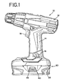
- Fig. 1 is a side view of a device in the form of a power tool incorporating the window of the present invention and one embodiment of a battery having a fuel gauge located on the battery such that the fuel gauge on the battery is visible through a window provided on the tool housing.
- Fig. 2 is an exploded side view of the device of Fig. 1 with the battery having a fuel gauge located on a portion of the battery.
- Fig. 3 is a side view of a device in the form of a power tool incorporating the window of the present invention and one embodiment of a battery having a fuel gauge located on the battery such that the fuel gauge on the battery is visible through a window provided on the tool housing.
- Fig. 4 is an exploded side view of the device of Fig. 3 and incorporating a fuel gauge that can be viewed through a window provided on the device.
- Fig. 5 is a schematic of a portion of a controller configured to cooperate with the fuel gauge of either Fig. 2 or Fig. 4 .
- Figure 1 shows a cordless device 10 and, in particular, a drill and a battery pack 20 electrically connectable to the cordless device for powering the cordless device.
- the battery pack 20 may be charged in a charger (not shown) as is known.
- the cordless device 10 may be any type cordless device 10, but for simplicity of description it will be described in connection with a power tool and, in particular, a drill. It will of course be appreciated, that the cordless device 10 may include, but is not limited to screwdrivers, rotary tools, hand-held power tools, reciprocating saws, hammer drills, routers, circular saws, grinders, sanders, buffers, and the like, as well as outdoor tools such as trimmers, sprayers, saws, edgers, cutters, etc.
- the principles of the present invention can be applied to other types of battery powered devices such as flashlights, home appliances such as blenders, fans, radios, and the like.
- the device 10 has a housing 12 and a motor (not shown) disposed in the housing for driving a tool or performing any other action.
- the particular device 10 shown in Fig. 1 has a handle 14 for gripping by the user.
- the device 10 is electrically connectable to a battery pack 20.
- the battery pack 20 has a housing 22 and at least one battery cell disposed within the housing 22.
- the cell may have a chemistry of seal lead acid, hydrogen, methanol fuel cell, lithium, lithium-ion, nickel cadmium, nickel metal hydride or other suitable battery chemistry, which those of skill in the art can appreciate.
- the battery pack 20 shown in the particular embodiment of Fig. 2 has a stem 24 that extends from the housing 22 to define a proximal end 26 and a distal end 28.
- the stem 24 has battery terminals (not shown) that connect with device terminals (not shown) of the device to provide an electrical connection.
- the battery terminals may be located at the distal end 28.
- the stem 24 is configured to be slidably received by the handle 14.
- the stem 24 is configured to be slidably received by the handle 14 of the device 10 in a manner such that the stem 24 can be engaged with the handle 14 only when the stem 24 is in mating relationship with the handle 14. Because the stem 24 is configured in this manner, the battery pack 20 can not pivot about the axis of the handle 14 when the battery pack 20 is engaged with the handle 14 of the device 10.
- At least one of the battery pack 20 and the device 10 has a latching mechanism 40 for temporarily engaging the other of the battery pack 20 and the device 10 to selectively secure the battery pack 20 and the device 10 together.
- the latching mechanism 40 includes a latch 42 that engages the device housing 12, and a button 44 that can be moved by the user to move the latch 42 to an unlatched position so that the battery pack 20 can be removed from the device 10.
- the battery pack 20 may be electrically connectable to a charger (not shown) for charging the battery cells.
- the battery pack 20 has a fuel gauge 50 to display a state of charge of the battery cell(s) within the battery pack 20.
- the fuel gauge 50 is incorporated in at least a portion of the battery housing 22.
- the fuel gauge 50 is located on the battery pack 20 at a location such that it is registered with a window 16 provided on the device housing 12 and such that the fuel gauge 50 is visible through the window 16.
- the window 16 may be open or covered with a material through which the fuel gauge 50 can be viewed. In this regard, the window 16 can be translucent or transparent.
- the fuel gauge 50 is located on the stem 24 portion of the battery pack 20 typically between the proximal end 26 and the distal end 28. It will be appreciated that by locating the fuel gauge 50 in this manner, the fuel gauge 50 will not only be visible when the battery pack 20 is engaged and is not engaged with the device housing 12 but also the fuel gauge 50 will be protected by the device housing 12 when the battery pack 20 is engaged with the device housing 12.
- the fuel gauge 50 can include a display 52, which may take any of several forms.
- the display 52 may have at least one and may have two or more indicator lights 54 (e.g. light-emitting diodes) one of which is green and the other red.
- the green light may be illuminated when the state of charge of the battery pack 20, 30 is acceptable and the red light may be illuminated when the state of charge of the battery pack 20 is low.
- Figs. 3 and 4 show another embodiment of a battery pack 20' incorporating features of the present invention.
- the battery pack 20' includes a housing 22' within which at least one battery cell (not shown) is located.
- the housing 22' has a pair of rails 34 that engage corresponding structure provided at the foot of the handle 12' of the device housing 12'.
- the battery pack 20' may be electrically connectable to a charger (not shown) for charging the battery cells.
- the battery pack 20' has a fuel gauge 50' to display a state of charge of the battery cell(s) within the battery pack 20'.
- the fuel gauge 50' is located on or adjacent a rail 34 of the battery pack housing 22'.
- the fuel gauge 50' is located on the battery pack 20' at a location such that it is registered with a window 16' provided on the device housing 12' and such that the fuel gauge 50' is visible through the window.
- the window 16' may be open or covered with a material through which the fuel gauge 50' can be viewed. In this regard, the window 16' can be translucent or transparent.
- the display 52' can also include a series of indicator lights 54' (e.g., light-emitting diodes) arranged to form a scale.
- the lights 54' are arranged in a horizontal manner.
- the lights 54' could be arranged in any suitable manner so long as they register with the window 16'.
- a number of indicator lights 54' can be illuminated when the battery state of charge is high and one or no lights 54' can be illuminated to show that the battery state of charge is low. In other embodiments, one light can flash to show that the battery state of charge is low.
- the display 52' can include other display screens and/or indicator lights having other relative orientations and positions and can include indicator lights of different colors (e.g., green, blue, yellow, orange, and red) for displaying the state of charge of the battery.
- the display 52' can be used to inform the user of other conditions, such as, for example, abnormal (high or low) battery temperature, an electrical fault within the electrical circuit, or other information pertaining to the battery or the device.
- the state of charge of the battery pack 20' can be determined prior to coupling the battery pack 20' with the device 10'.
- the fuel gauge 50 and 50' is associated with an electrical circuit 56 that includes a controller 58 for performing various functions, such as, for example, measuring various battery pack 20, 20' conditions (e.g., state of charge of battery cell), controlling the fuel gauge, controlling operation of the tool, and gathering and storing data pertaining to the device 10 operation or battery pack 20, 20' conditions.
- a controller 58 for performing various functions, such as, for example, measuring various battery pack 20, 20' conditions (e.g., state of charge of battery cell), controlling the fuel gauge, controlling operation of the tool, and gathering and storing data pertaining to the device 10 operation or battery pack 20, 20' conditions.
- the controller 58 is programmed to measure the state of charge in response to movement of the button 44, 44' associated with the latch mechanism 40, 40'.
- movement of the button 44, 44' such as by depressing the button 44, 44', which moves the latch 42, 42', causing a signal to be sent to the controller 58 to measure the state of charge of the battery pack 20, 20' and to send a signal to the display 52, 52'.
- only one button 44, 44' need be actuated (depressed) to actuate the operation of the controller 58.
- both buttons need be depressed (simultaneously or substantially simultaneously) in order to actuate operation of the controller 58.
- the battery state of charge data may be measured prior to activation of the motor; that is, before the battery state of charge is affected by the current draw being supplies to the motor.
- This measurement of the battery state of charge represents an at rest state of charge of the battery pack 20, 20'.
- the at rest state of charge measurement is displayed by the fuel gauge 50, 50'.
- the state of charge data may be displayed for a predetermined time after the button 44, 44' is actuated.
- the predetermined time may be any suitable selected time such as a few seconds. Of course, it will be understood that the selected time can be greater than a few seconds or can be less than a few seconds. After the selected time is exceeded, the display can be cleared.
- the display 52, 52' is cleared when the selected time expires regardless of whether the button 44, 44' is still actuated. In some embodiments, the display 52, 52' is cleared prior to expiration of the selected time (e.g., approximately a few seconds) when the button 44, 44' is released.
- the controller 58 may operate to cause a measurement and display of the battery state of charge when the trigger 18, 18' (or other device for activating the motor or operation of the device) is actuated instead of when the latch button 44, 44' is actuated. Further, it is contemplated that the controller 58 may operate to cause a measurement and display of the battery state of charge when a button, latch, or actuator other than the above-described trigger 18, 18' or button 44, 44' are actuated. In this regard, either the battery housing 22, 22' or the device housing 12, 12' may have a button that, when actuated, will cause the display 52 to indicate the state of charge of the battery pack 20, 20'.
- the device housing 12, 12' is provided with a window 16, 16' that is registered with the fuel gauge 50, 50' when the battery pack 20, 20' is coupled with the device 10, 10' and through which the fuel gauge 50, 50' is visible.
- the window 16, 16' is located, sized, and shaped in a manner that is complementary to the size and shape of the display 52, 52'. Accordingly, even when the battery pack 20, 20' is coupled with the device 10, 10', the display 52, 52' for the fuel gauge 50, 50' is still visible.
- the present invention provides an easily viewable fuel gauge 50, 50' for a battery powered device 10, 10'.
- the foregoing description of the invention has been presented for purposes of illustration and description, and is not intended to be exhaustive or to limit the invention to the precise form disclosed. It will be apparent to those skilled in the art that the present invention is susceptible of many variations and modifications coming within the scope of the following claims. These additions and/or alterations are considered to be equivalents of the present invention. Though the present invention is described above in connection with a tool, and particularly in connection with a drill, it should be understood that the present invention is not limited and various modifications will be apparent to those of skill in the art. It is therefore not intended that the present be limited to the disclosed embodiments or details but that the present invention includes all variations and alternative embodiments with the scope of the present invention as defined in the claims.
Landscapes
- Engineering & Computer Science (AREA)
- Chemical & Material Sciences (AREA)
- Chemical Kinetics & Catalysis (AREA)
- Electrochemistry (AREA)
- General Chemical & Material Sciences (AREA)
- Manufacturing & Machinery (AREA)
- Life Sciences & Earth Sciences (AREA)
- Biophysics (AREA)
- Computer Hardware Design (AREA)
- Battery Mounting, Suspending (AREA)
- Charge And Discharge Circuits For Batteries Or The Like (AREA)
- Secondary Cells (AREA)
Applications Claiming Priority (1)
| Application Number | Priority Date | Filing Date | Title |
|---|---|---|---|
| US12/126,191 US20090289805A1 (en) | 2008-05-23 | 2008-05-23 | Device With Window For Viewing Fuel Gauge On Battery |
Publications (2)
| Publication Number | Publication Date |
|---|---|
| EP2124287A2 true EP2124287A2 (de) | 2009-11-25 |
| EP2124287A3 EP2124287A3 (de) | 2009-12-02 |
Family
ID=41059714
Family Applications (1)
| Application Number | Title | Priority Date | Filing Date |
|---|---|---|---|
| EP09250115A Withdrawn EP2124287A3 (de) | 2008-05-23 | 2009-01-16 | Vorrichtung mit Fenster zur Ansicht eines Kraftstoffmessgeräts auf einer Batterie |
Country Status (4)
| Country | Link |
|---|---|
| US (1) | US20090289805A1 (de) |
| EP (1) | EP2124287A3 (de) |
| CN (1) | CN101587171A (de) |
| AU (1) | AU2008249170A1 (de) |
Cited By (2)
| Publication number | Priority date | Publication date | Assignee | Title |
|---|---|---|---|---|
| DE102011004964A1 (de) * | 2011-03-02 | 2012-04-26 | Siemens Medical Instruments Pte. Ltd. | Hörvorrichtung mit Indikatorvorrichtung |
| EP2756808A1 (de) * | 2013-01-16 | 2014-07-23 | Covidien LP | Handgeführtes elektromechanisches chirurgisches System mit Batteriefachdiagnoseanzeige |
Families Citing this family (14)
| Publication number | Priority date | Publication date | Assignee | Title |
|---|---|---|---|---|
| JP5461221B2 (ja) | 2010-02-12 | 2014-04-02 | 株式会社マキタ | 複数のバッテリパックを電源とする電動工具 |
| JP5432761B2 (ja) * | 2010-02-12 | 2014-03-05 | 株式会社マキタ | 複数のバッテリパックを電源とする電動工具 |
| JP5662105B2 (ja) * | 2010-10-26 | 2015-01-28 | 株式会社マキタ | 二次電池パック |
| US8766783B1 (en) * | 2010-11-05 | 2014-07-01 | Google Inc. | Methods and systems for remotely controlling electronics |
| JP5892382B2 (ja) * | 2012-07-30 | 2016-03-23 | 日立工機株式会社 | 電動工具 |
| US9263716B2 (en) * | 2013-02-21 | 2016-02-16 | Lutron Electronics Co., Inc. | Monolithic battery holder having resilient retention strap for use in battery-powered sensor |
| US20140329119A1 (en) * | 2013-05-02 | 2014-11-06 | Black & Decker Inc. | Rubber boot for battery pack |
| USD727255S1 (en) * | 2014-07-03 | 2015-04-21 | Lightforce Australia Pty Ltd. | Battery pack for hand held electrical device |
| JP6300271B2 (ja) * | 2014-07-22 | 2018-03-28 | 株式会社マキタ | チェーンソー |
| AU362572S (en) | 2014-11-26 | 2015-07-15 | Techtronic Ind Co Ltd | Battery |
| DE102015218447B4 (de) * | 2014-12-16 | 2025-01-23 | Robert Bosch Gmbh | Akkupack für eine Handwerkzeugmaschine mit Leuchtelement |
| CN112838322A (zh) * | 2019-11-07 | 2021-05-25 | 南京德朔实业有限公司 | 电池包及包含该电池包的电动工具 |
| US11901527B2 (en) | 2020-07-15 | 2024-02-13 | Emerson Electric Co. | Battery packs for battery-powered appliances and connection system for same |
| US20230283092A1 (en) * | 2022-03-01 | 2023-09-07 | Whirlpool Corporation | Charger and battery for cordless appliance |
Family Cites Families (27)
| Publication number | Priority date | Publication date | Assignee | Title |
|---|---|---|---|---|
| US5130658A (en) * | 1990-02-28 | 1992-07-14 | Display Matrix Corporation | Apparatus and method for indicating state of charge of a battery |
| JPH04102783U (ja) * | 1991-02-15 | 1992-09-04 | 日東工器株式会社 | Dcバツテリ駆動型ハンド工具 |
| US5898290A (en) * | 1995-09-07 | 1999-04-27 | Norand Corporation | Battery pack with capacity and pre-removal indicators |
| KR200161967Y1 (ko) * | 1997-05-01 | 1999-12-01 | 윤종용 | 휴대용 전자제품 |
| JPH11266543A (ja) * | 1998-03-18 | 1999-09-28 | Makita Corp | 電動工具充電システム |
| JP3762104B2 (ja) * | 1998-07-02 | 2006-04-05 | 株式会社マキタ | 電動工具充電システム |
| US6232782B1 (en) * | 1999-04-16 | 2001-05-15 | The Gillette Company | On cell circumferential battery indicator |
| EP1929940A3 (de) * | 2000-03-14 | 2008-06-25 | Kabushiki Kaisha Toshiba | MRI-Systemcenter und MRI-System |
| US7359762B2 (en) * | 2002-04-18 | 2008-04-15 | Black & Decker Inc. | Measurement and alignment device including a display system |
| KR100883986B1 (ko) * | 2002-07-09 | 2009-02-17 | 엘지디스플레이 주식회사 | 콜레스테릭 액정 컬러필터과 콜레스테릭 액정 편광판을포함하는 액정표시장치 |
| GB2392002B (en) * | 2002-08-12 | 2004-10-13 | Choon Nang Elec Appl Mfy Ltd | Rechargeable battery pack |
| US6950030B2 (en) * | 2002-09-05 | 2005-09-27 | Credo Technology Corporation | Battery charge indicating circuit |
| US7157882B2 (en) * | 2002-11-22 | 2007-01-02 | Milwaukee Electric Tool Corporation | Method and system for battery protection employing a selectively-actuated switch |
| US7253585B2 (en) * | 2002-11-22 | 2007-08-07 | Milwaukee Electric Tool Corporation | Battery pack |
| JP3990990B2 (ja) * | 2003-01-24 | 2007-10-17 | キヤノン株式会社 | 充電装置、電子機器、充電装置における電池残量表示制御方法、電子機器における電池残量検出方法 |
| JP3980509B2 (ja) * | 2003-04-01 | 2007-09-26 | 株式会社マキタ | 二次電池装置 |
| TWM248566U (en) * | 2003-12-18 | 2004-11-01 | Mobiletron Electronics Co Ltd | Electric tool |
| US20050275378A1 (en) * | 2004-06-14 | 2005-12-15 | Serafino Canino | Apparatus and method for illuminated battery charging device |
| US7176656B2 (en) * | 2004-06-22 | 2007-02-13 | Campbell Hausfeld/Scott Fetzer Company | Tool with battery pack |
| DE202004020791U1 (de) * | 2004-08-09 | 2006-01-12 | Robert Bosch Gmbh | Akkuschrauber |
| US7492125B2 (en) * | 2004-11-04 | 2009-02-17 | Milwaukee Electric Tool Corporation | Power tools, battery chargers and batteries |
| JP4096951B2 (ja) * | 2005-03-28 | 2008-06-04 | 松下電工株式会社 | 電気機器 |
| US20060251958A1 (en) * | 2005-05-05 | 2006-11-09 | Adan Ayala | Battery charge indicator |
| JP2006321043A (ja) * | 2005-05-17 | 2006-11-30 | Milwaukee Electric Tool Corp | 動力工具、バッテリ、充電器、およびそれらを動作させる方法 |
| TWM287505U (en) * | 2005-08-24 | 2006-02-11 | Aebos Technology Co Ltd | Electrical device |
| US20070082667A1 (en) * | 2005-10-06 | 2007-04-12 | Lucent Technologies, Inc. | Process for migrating a mobile station identity from a mobile identification number to an international mobile station identity |
| US7656131B2 (en) * | 2005-10-31 | 2010-02-02 | Black & Decker Inc. | Methods of charging battery packs for cordless power tool systems |
-
2008
- 2008-05-23 US US12/126,191 patent/US20090289805A1/en not_active Abandoned
- 2008-11-21 AU AU2008249170A patent/AU2008249170A1/en not_active Abandoned
- 2008-12-24 CN CNA2008101881665A patent/CN101587171A/zh active Pending
-
2009
- 2009-01-16 EP EP09250115A patent/EP2124287A3/de not_active Withdrawn
Cited By (6)
| Publication number | Priority date | Publication date | Assignee | Title |
|---|---|---|---|---|
| DE102011004964A1 (de) * | 2011-03-02 | 2012-04-26 | Siemens Medical Instruments Pte. Ltd. | Hörvorrichtung mit Indikatorvorrichtung |
| EP2756808A1 (de) * | 2013-01-16 | 2014-07-23 | Covidien LP | Handgeführtes elektromechanisches chirurgisches System mit Batteriefachdiagnoseanzeige |
| EP3005955A1 (de) * | 2013-01-16 | 2016-04-13 | Covidien LP | Handgeführtes elektromechanisches chirurgisches system mit batteriefachdiagnoseanzeige |
| EP3005955B1 (de) | 2013-01-16 | 2017-08-02 | Covidien LP | Handgeführtes elektromechanisches chirurgisches system mit batteriefachdiagnoseanzeige |
| US10265090B2 (en) | 2013-01-16 | 2019-04-23 | Covidien Lp | Hand held electromechanical surgical system including battery compartment diagnostic display |
| US10463382B2 (en) | 2013-01-16 | 2019-11-05 | Covidien Lp | Hand held electromechanical surgical system including battery compartment diagnostic display |
Also Published As
| Publication number | Publication date |
|---|---|
| CN101587171A (zh) | 2009-11-25 |
| AU2008249170A1 (en) | 2009-12-10 |
| US20090289805A1 (en) | 2009-11-26 |
| EP2124287A3 (de) | 2009-12-02 |
Similar Documents
| Publication | Publication Date | Title |
|---|---|---|
| EP2124287A2 (de) | Vorrichtung mit Fenster zur Ansicht eines Kraftstoffmessgeräts auf einer Batterie | |
| US7557534B2 (en) | Power tool, battery, charger and method of operating the same | |
| US7649337B2 (en) | Power tool including a fuel gauge and method of operating the same | |
| US20090202894A1 (en) | Battery connection for a power tool | |
| EP2003761A2 (de) | Adapter für schnurlose elektrische Werkzeuge | |
| US9583746B2 (en) | Electric tool powered by a plurality of battery packs and adapter therefor | |
| US20140014384A1 (en) | Power tool | |
| EP2015421A2 (de) | Rücksetzmechanismus für ein Batteriepaket | |
| US9331365B2 (en) | Shared control of thermistor and dual purpose thermistor line | |
| US8901887B2 (en) | Mobile electric appliance with charge status indicator and battery for it | |
| JP2012051064A (ja) | 電動工具及び電動工具に用いられる電池パック | |
| JP2013070504A (ja) | 電気機器 | |
| US20070227310A1 (en) | Hand power tool | |
| US20070229027A1 (en) | Hand power tool | |
| CN114556985B (zh) | 电池组及电气设备系统 | |
| CN102301246B (zh) | 具有高电流和低电流放电接线柱的电池组盒 | |
| CN100555734C (zh) | 蓄电池组充电器操作方法 | |
| JP6032333B2 (ja) | コネクタ装置およびそれを備える電源装置 | |
| EP1890358B1 (de) | Batterieladungsanzeiger | |
| US20070229008A1 (en) | Hand power tool | |
| CN117597820A (zh) | 电池组及电气设备 | |
| JP2021044203A (ja) | 電池パック及び電池パックを用いた電気機器 | |
| JP2004098203A (ja) | 手持ち電動工具 | |
| JP2012050341A (ja) | 電動耕耘機 | |
| EP2391896A1 (de) | Batteriepack mit hoch- und niedrigstromentladungsklemmen |
Legal Events
| Date | Code | Title | Description |
|---|---|---|---|
| PUAI | Public reference made under article 153(3) epc to a published international application that has entered the european phase |
Free format text: ORIGINAL CODE: 0009012 |
|
| PUAL | Search report despatched |
Free format text: ORIGINAL CODE: 0009013 |
|
| AK | Designated contracting states |
Kind code of ref document: A2 Designated state(s): AT BE BG CH CY CZ DE DK EE ES FI FR GB GR HR HU IE IS IT LI LT LU LV MC MK MT NL NO PL PT RO SE SI SK TR |
|
| AX | Request for extension of the european patent |
Extension state: AL BA RS |
|
| AK | Designated contracting states |
Kind code of ref document: A3 Designated state(s): AT BE BG CH CY CZ DE DK EE ES FI FR GB GR HR HU IE IS IT LI LT LU LV MC MK MT NL NO PL PT RO SE SI SK TR |
|
| AX | Request for extension of the european patent |
Extension state: AL BA RS |
|
| 17P | Request for examination filed |
Effective date: 20100506 |
|
| 17Q | First examination report despatched |
Effective date: 20100607 |
|
| AKX | Designation fees paid |
Designated state(s): AT BE BG CH CY CZ DE DK EE ES FI FR GB GR HR HU IE IS IT LI LT LU LV MC MK MT NL NO PL PT RO SE SI SK TR |
|
| STAA | Information on the status of an ep patent application or granted ep patent |
Free format text: STATUS: THE APPLICATION IS DEEMED TO BE WITHDRAWN |
|
| 18D | Application deemed to be withdrawn |
Effective date: 20101019 |