EP2124394A2 - Bateau ayant un système de bateau à deux directions centrales placées avant - Google Patents
Bateau ayant un système de bateau à deux directions centrales placées avant Download PDFInfo
- Publication number
- EP2124394A2 EP2124394A2 EP09160464A EP09160464A EP2124394A2 EP 2124394 A2 EP2124394 A2 EP 2124394A2 EP 09160464 A EP09160464 A EP 09160464A EP 09160464 A EP09160464 A EP 09160464A EP 2124394 A2 EP2124394 A2 EP 2124394A2
- Authority
- EP
- European Patent Office
- Prior art keywords
- ship
- bus
- subsystems
- subring
- central
- Prior art date
- Legal status (The legal status is an assumption and is not a legal conclusion. Google has not performed a legal analysis and makes no representation as to the accuracy of the status listed.)
- Withdrawn
Links
- 238000012544 monitoring process Methods 0.000 claims abstract description 26
- 238000010248 power generation Methods 0.000 claims abstract description 18
- 238000012806 monitoring device Methods 0.000 claims description 26
- 230000003287 optical effect Effects 0.000 claims description 17
- 238000004891 communication Methods 0.000 claims description 8
- 101710141933 Single-stranded DNA-binding protein 1 Proteins 0.000 claims description 4
- 101710141937 Single-stranded DNA-binding protein 3 Proteins 0.000 claims description 4
- 101710141938 Single-stranded DNA-binding protein 2 Proteins 0.000 claims 2
- 239000002131 composite material Substances 0.000 claims 1
- 230000008878 coupling Effects 0.000 description 12
- 238000010168 coupling process Methods 0.000 description 12
- 238000005859 coupling reaction Methods 0.000 description 12
- 230000005540 biological transmission Effects 0.000 description 10
- 230000002093 peripheral effect Effects 0.000 description 8
- 230000002457 bidirectional effect Effects 0.000 description 2
- 230000009977 dual effect Effects 0.000 description 2
- 239000000835 fiber Substances 0.000 description 2
- 238000001914 filtration Methods 0.000 description 2
- 230000001681 protective effect Effects 0.000 description 2
- 238000012800 visualization Methods 0.000 description 2
- RYGMFSIKBFXOCR-UHFFFAOYSA-N Copper Chemical compound [Cu] RYGMFSIKBFXOCR-UHFFFAOYSA-N 0.000 description 1
- 238000002485 combustion reaction Methods 0.000 description 1
- 239000004020 conductor Substances 0.000 description 1
- 229910052802 copper Inorganic materials 0.000 description 1
- 239000010949 copper Substances 0.000 description 1
- 230000001419 dependent effect Effects 0.000 description 1
- 238000001514 detection method Methods 0.000 description 1
- 238000005516 engineering process Methods 0.000 description 1
- 230000001360 synchronised effect Effects 0.000 description 1
Images

Classifications
-
- H—ELECTRICITY
- H04—ELECTRIC COMMUNICATION TECHNIQUE
- H04L—TRANSMISSION OF DIGITAL INFORMATION, e.g. TELEGRAPHIC COMMUNICATION
- H04L12/00—Data switching networks
- H04L12/28—Data switching networks characterised by path configuration, e.g. LAN [Local Area Networks] or WAN [Wide Area Networks]
- H04L12/46—Interconnection of networks
- H04L12/4637—Interconnected ring systems
-
- H—ELECTRICITY
- H04—ELECTRIC COMMUNICATION TECHNIQUE
- H04L—TRANSMISSION OF DIGITAL INFORMATION, e.g. TELEGRAPHIC COMMUNICATION
- H04L12/00—Data switching networks
- H04L12/28—Data switching networks characterised by path configuration, e.g. LAN [Local Area Networks] or WAN [Wide Area Networks]
- H04L12/40—Bus networks
- H04L12/40169—Flexible bus arrangements
- H04L12/40176—Flexible bus arrangements involving redundancy
- H04L12/40189—Flexible bus arrangements involving redundancy by using a plurality of bus systems
-
- H—ELECTRICITY
- H04—ELECTRIC COMMUNICATION TECHNIQUE
- H04L—TRANSMISSION OF DIGITAL INFORMATION, e.g. TELEGRAPHIC COMMUNICATION
- H04L12/00—Data switching networks
- H04L12/28—Data switching networks characterised by path configuration, e.g. LAN [Local Area Networks] or WAN [Wide Area Networks]
- H04L12/46—Interconnection of networks
- H04L12/4604—LAN interconnection over a backbone network, e.g. Internet, Frame Relay
- H04L12/4616—LAN interconnection over a LAN backbone
-
- H—ELECTRICITY
- H04—ELECTRIC COMMUNICATION TECHNIQUE
- H04L—TRANSMISSION OF DIGITAL INFORMATION, e.g. TELEGRAPHIC COMMUNICATION
- H04L12/00—Data switching networks
- H04L12/28—Data switching networks characterised by path configuration, e.g. LAN [Local Area Networks] or WAN [Wide Area Networks]
- H04L12/40—Bus networks
- H04L2012/40267—Bus for use in transportation systems
- H04L2012/40286—Bus for use in transportation systems the transportation system being a waterborne vessel
Definitions
- the invention relates to a ship with a ship system, in particular power generation, propulsion or ship operating system, with two higher-level central controls according to claim 1.
- the DE 10 2004 041 824 A1 discloses a ship with a ship propulsion system consisting of two separately and in combination operable partial drive systems, each with its own programmable logic controller for controlling and monitoring the respective partial drive system and each having a subring bus, via which the controller is connected to components of the subsystem for their control and monitoring, wherein the subring buses of the two subsystems are connected to one another via a main ring bus and to a higher-level HMI (Human Machine Interface).
- HMI Human Machine Interface
- the main ring bus forms with the Subringbussen a data network.
- the subring bus is connected to the main ring bus via a single network switch, in particular a switch which is connected both in the subring bus and in the main ring bus.
- a switch is an electronic device for connecting a subordinate network to a higher-level network.
- a subring bus is a subnetwork in bus form that is physically separate from the rest of the data network, ie the main ring bus and other subring buses.
- the main ring bus and the subring buses are preferably designed with double redundancy based on optical waveguides.
- the controller is connected to the subring bus of the respective subsystem together with field devices and input and output modules.
- two superordinate central controls are provided for each of the subsystems, in each case instead of a separate controller for each of the subsystems.
- Each of the two higher-level central controllers is able to control and monitor all subsystems. This provides redundancy in the control and monitoring of all subsystems, whereby the reliability of the ship system can be increased.
- the number of controllers can be reduced. For example, in the case of four subsystems instead of a separate control for each of the subsystems, i. a total of four controls, only the two higher-level central controls needed.
- the data traffic in the respective Subringbus and thus its probability of failure and delay times in the data transmission can be kept small because data exchanged, for example, between the two central controllers or a central controller and a have to be exchanged parent control and observation level, then need not be fed into the Subringbus and thus not burden this.
- the central controls are set up and coupled to one another in such a way that the first central control controls and monitors all ship subsystems via the first subring bus and that in the event of failure of the first central control or the first subring bus then the second Central control over the second Subringbus controls and monitors all ship subsystems.
- the first central controller is active (i.e., takes on the role of a "master") and alone controls and monitors all subsystems while the other controller remains passive (“slave").
- the other controller until then inactive, second central controller can then become active (ie take over the function of the master) and take over control and monitoring of all subsystems via the second subring bus alone.
- the central higher-level control systems of the two ship subsystems are connected via the main ring bus with a higher-level control and monitoring device, wherein the operating and monitoring device preferably directly, ie without a communication bus connected in between, is connected to the main ring bus.
- the operating and monitoring device preferably directly, ie without a communication bus connected in between, is connected to the main ring bus. Due to the redundancy at the level of control and monitoring by the higher-level central controls, however, in the event of failure of one of the central controls or one of the subring buses, the operability and observability of the ship's system continues to be ensured from the bridge. Due to its low complexity, such a system is characterized by particularly fast and fail-safe communication between the controls and the operating and monitoring level.
- a further increase in reliability can be achieved by physically separating the higher-level central controllers from both the respective subring bus and the main ring bus.
- the parent central controls are additionally connected to each other via a direct line connection.
- a software balance between the two controllers can take place via this line connection. If, for example, a new version of the control software is loaded onto one of the two controllers, then this software can be automatically transmitted via the line connection to the other controller and be imported into this. As a result, for example, a virtually bumpless software update is possible and it is ensured that the same control software is stored in both controllers.
- a mutual life-death query of the two controllers for example, by exchanging life-character telegrams, take place.
- the inactive controller does not receive a life-piece telegram from the active controller, it can send a message to the active controller via the line connection that it takes over the master role and is now the active controller. It is essential that due to the direct line connection of the main ring bus not additional is burdened by the traffic between the two controllers. In addition, a data transmission between the two controllers is also possible regardless of the functionality of the main ring bus. As a result, the reliability can be further increased.
- the higher-level central controls can be arranged spatially different, especially in different maritime security areas in the ship.
- a further increase in the reliability is also possible because the ship subsystems are spatially different, especially in different maritime security areas, arranged in the ship.
- the subring buses can therefore also each extend over two or more vessel protection areas.
- each of the subring buses is connected to a local operating and monitoring device.
- Autarkic in this context means that the ship system is independent of a higher level, e.g. an operating and monitoring device, its functionality can be maintained independently, especially in case of need or emergency, e.g. in case of fire and failure of the higher level.
- each of the ship subsystems comprises a plurality of subsystems, each having a plurality of subsystem components, which are in each case via a star-shaped bus system with each other and each with two Subringbussen in combination.
- a star-shaped bus system with each other and each with two Subringbussen in combination.
- the main ring bus is designed as a double redundant ring bus. This also allows redundancy on the operating and monitoring level.
- the skin ring bus Due to its low susceptibility to interference and the high data transmission capacity of the skin ring bus is advantageous as a fiber optic ring bus is formed, which preferably uses the Ethernet protocol.
- the subring buses are advantageously designed in each case as a fiber-optic ring bus, which preferably uses the Profibus protocol.
- FIG. 1 shows a schematic representation of a side view of a ship 1 with a higher-level control and monitoring system 2 and a ship system in the form of a power generation system 3 consisting of two subsystems 4a, 4b, which are operable individually and in combination.
- the operating and monitoring system 2 comprises a double redundant main ring bus 5 and two operating and monitoring devices 6, which are connected or connected directly to the main ring bus 5.
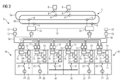
- Each of the subsystems 4a, 4b Each comprises an equal number of subsystems, in each case two power generation units 20 and one power coupling unit 30 each.
- the power generation system 3 comprises a first superordinate central control 7a and a second superordinate central control 7b for controlling and monitoring respectively of both subsystems 4a, 4b, the first superordinate central control 7a via a first subring bus 8a and the second superordinate central control 7b via a second Subringbus 8a to be controlled and monitored subsystems 20, 30 each of subsystems 3a, 3b is connected.
- the first subring bus 8a is connected via the first central superordinate controller 7a and the second subring bus 8b via the second superordinate central controller 7b directly to the main ring bus 5 and thus connected to the higher-level operating and monitoring devices 6.
- the superordinate central controllers 7a, 7b are connected to each other for synchronization via a direct line connection 15, via which, for example, an automatic software update can be carried out quickly or directly, or life-sign telegrams can be exchanged between the controllers 7a, 7b without the main ring bus 5 for this purpose burdened with additional traffic.
- the two subsystems 4a, 4b are arranged in the ship's longitudinal direction in each of the ship's different securing areas.
- the subsystem 4a is arranged in a ship security area SSB 3 in the stern of the ship and the subsystem 4b in a ship security area SSB 1 in the front ship.
- the main ring bus 8, the subring buses 8a, 8b and the direct line connection therefore extend in the ship's longitudinal direction over several ship securing areas SSB 3 to SSB 1 from the stern to the fore ship.
- the central controls 7a, 7b are spatially different from the remaining components of the subsystems 4a, 4b in the ship 1 (e.g., in different rooms of the ship).
- the two subsystems 4a, 4b also be arranged in the ship's transverse direction in each case different hull areas of the ship (to simplify the illustration in FIG FIG. 2 the main ring bus 5 and the operating and monitoring devices 6 have been omitted).
- the subsystem 4a is disposed in a ship security area SSB X on the port side of the ship
- the subsystem 4b is disposed in a ship security area SSB Y on the starboard side of the ship.
- the main ring bus 8, the subring buses 8a, 8b and the direct line connection 15 therefore extend in the ship's transverse direction from the port side to the starboard side over at least two ship securing areas of the ship.
- the central controls 7a, 7b here also spatially different from the remaining components of the subsystems 4a, 4b arranged in the ship 1 (eg, in different rooms of the ship).
- an electrical system of the ship comprises two interconnected busbars 10, 11.
- the power generation units 20 of the subsystem 4a are used to generate electrical energy for the busbar 10 and the power generation units 20 of the subsystem 4b are used to generate electrical energy for the busbar 11th
- the network coupling units 30 of the two subsystems 4a, 4b the two bus bars 10, 11 are connectable to each other.
- the two subsystems 4a, 4b are operable individually or in combination. You can thus each individually or both together in each case one or both coupled to each other busbars 10, 11 electrical energy.
- Each of the power generation units 20 comprises an internal combustion engine, not shown in detail, preferably driven by a diesel engine 21, a switch 22 for switching on or off the generator 21 to the respective busbar 10 or 11 and a plurality of peripheral devices 23, 24, 25, here a generator protection device 23, for example, to protect the generator 21 and the busbar 10 and 11 against short circuits and overvoltages, an input / output module 24 for analog and digital signals and a generator Synchronisier réelle 25 for synchronizing the generator 21 with the busbar 10 and 11 (eg for frequency and phase match).
- an internal combustion engine not shown in detail, preferably driven by a diesel engine 21, a switch 22 for switching on or off the generator 21 to the respective busbar 10 or 11 and a plurality of peripheral devices 23, 24, 25, here a generator protection device 23, for example, to protect the generator 21 and the busbar 10 and 11 against short circuits and overvoltages, an input / output module 24 for analog and digital signals and a generator Synchronisierêt 25 for synchronizing the generator 21 with the busbar 10 and 11
- Each of the network coupling units 30 comprises a clutch switch 32 and also a plurality of peripheral devices 33, 34, 35, here a protective device 33 to protect the clutch from short circuits, an input / output module 34 for analog and digital signals and a synchronizer 45 for synchronized connection of the associated clutch switch 32nd
- Each of the higher-level central controllers 7a, 7b can control and monitor the functions of the devices 23, 24, 25 or 33, 34, 45 of a power generation unit 20 or network coupling unit 30 and forms an automation system for the power generation unit 20 or network coupling unit 30 together with these devices
- This automation system takes over the task of a power management system, ie it controls the synchronization and connection or disconnection of a generator 21 to or from the busbar 10 or 11, protects the generator 21 and the busbar 10 and 11 against unauthorized Operating conditions (eg short circuits), determines the electrical system available to the electrical system and required by marine consumers, controls the connection and disconnection of consumers to or from the busbars 10, 11 or controls the clutch the two busbars 10, 11 by means of the two clutch switch 32nd
- the main ring bus 5 is configured twice as redundant as Industrial Ethernet based on optical waveguides with a bidirectional data transmission (ie a data transmission in both ring directions). For dual redundancy, the main ring bus has a dual routing, i. There are two bus rings 5a, 5b available.
- Each of the subring buses 8a, 8b is simply redundantly formed as a fiber based profibus with bidirectional data transmission (i.e., data transmission in both ring directions).
- optical network switch 9 which are designed as Industrial Ethernet Optical Switch Module and the Physically decouple components from the main ring bus 5 and by filtering the data traffic in the main ring bus 5 based on Ethernet addresses of the components or subsystems connected to the main ring bus 5 ensure that only data for the respective component or the respective subsystem are forwarded to this ,
- a respective separate network switch 9 is provided for each of the two redundant bus rings 5a, 5b.
- a network switch 9 converts the optical Ethernet signals into electrical Ethernet signals and vice versa.
- the connection of communicating components or subsystems of the subsystems 4a and 4b (here the central controller 7, the peripheral devices 23, 24, 25, 33, 34, 35 and a local operating and monitoring device 12) to each of the two subring buses 8a, 8b via optical connection modules 13, which are called Profibus Optical Link module (network switch) are executed and which physically decouple the components of the Subringbussen 8a, 8b and ensure by filtering the traffic in the Subringbussen 8a, 8b based on Profibus addresses of the Subringbusse 8a, 8b connected components or subsystems that Only data for the respective component or the respective subsystem are also forwarded to this or this.
- the optical connection module 13 converts the optical Profibus signals into electrical Profibus signals and vice versa.
- the protective device 23, 33 and the input / output module 24, 34 of a power generation unit 20 and network coupling unit 30 are via a star-shaped bus 14 in copper technology (ie with electrical conductors), preferably a Profibus with each other and a coupling module 16, each with an optical Connection module (Optical Link Module) 13 for each of the Subringbusse 8a, 8b connected, via which the coupling of the field bus and thus these components 23, 24, 33, 34 to the parent subring buses 8a, 8b and thus also to the central controls 7a, 7b he follows.
- the coupling module 16 has the task to distribute the data received by the peripheral field devices 23, 24 or 33, 34 to both subring buses 5a, 5b and vice versa.
- the subring buses 8a, 8b are thus connected directly to the main ring bus 5 via their respective central control 7a, 7b. Since the connection takes place in each case via an optical network switch 9 connected in the main ring bus 2 and an optical connection module 13 connected in the subring bus 8, the central controllers 7a, 7b are physically separated both from the subring buses 8a, 8b and from the superordinate main ring bus 5 ,
- the active control of the inactive control In the event of a fault in the active control or in the subring bus 8a or 8b associated with it, the active control of the inactive control notifies the fault. To detect a total failure of the active control, the two controllers are connected to each other via life-character telegrams. If within a given time sign-of-life telegrams of the active control remain off, this interprets the hitherto inactive control as a failure of the active control.
- the hitherto inactive control Upon receipt of a fault message or detection of a total failure sends the hitherto inactive control both to the hitherto active control and to the coupling modules 16 a message that it takes over the control and monitoring of the subsystems 4a, 4b. Subsequently, the previously active control is inactive and sets the transmission of control commands via the subring bus assigned to the subsystems 4a, 4b and the transmission of observation data via the main ring bus 5 to the operating and monitoring devices 6. Instead, the hitherto inactive control is active and receives the sending of control commands via the subring bus assigned to it and the transmission of observation data via the main ring bus 5 to the operating and monitoring devices 6. For this purpose, the coupling modules 16 switch from a data forwarding from the subring bus of the now inactive control to a data forwarding from the subring bus of the now active control.
- the two local operating and monitoring device 12 are also in ship's longitudinal or transverse direction arranged in each case different hull securing areas of the ship 1.
- the local operator and monitor 12 provides on-site operators, e.g. in the engine room, all monitoring and control options, as they are also the captain on the bridge by means of the operating and monitoring devices 6 for the subsystems 4a, 4b are available. Thus, even if the operating and monitoring system 2 fails, the complete control and monitoring of the subsystems 4a, 4a can be carried out on site by, for example, the senior engineer.
- the ship 1 thus has a redundancy both on the operating and monitoring level as well as on the subordinate control and monitoring level.
- a central controller 7a or 7b is automatically switched to the other controller 7b and 7a.
- the sub-ring bus 8a or 8b of the active control 7a or 7b fails, it is possible to switch over to the other control 7b or 7a with the sub-ring bus 8b or 8a assigned to it.
- the operating and monitoring system 2 fails, an operation and observation can take place via the local operating and monitoring device 12 of the subring bus 8a or 8b of the active control 7a or 7b.
- a component or subsystem fails, other intact components or subsystems are available. Even if one subsystem 4a or 4b fails, the other subsystem 4b or 4a is still available and thus permits at least limited operation.
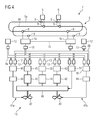
- FIG. 4 shows the operating and monitoring system of FIG. 1 with an attached drive system 40 as a ship system.
- the drive system 40 consists of two drive subsystems 41a, 41b, which are operable individually or in combination and thus can drive the ship 1 individually or in combination.
- 41a, 41b the same components are also provided with the same reference numerals.
- Two superordinate central controllers 7a, 7b are used to control and monitor both subsystems 41a, 41b.
- Each of the central controllers 7a, 7b is in this case connected in each case via its own associated subring bus 8a or 8b with components of both subsystems 41a, 41b for their control and monitoring.
- the subring buses 8a, 8b are connected via the central controllers 7a, 7b directly to the double redundant main ring bus 5, to which in turn directly the operating and monitoring devices 6 of the higher-level control and monitoring system 2 are connected.
- Each of the subsystems 41a, 41b respectively comprises an electric motor 42 for driving a propeller 43, an adjustment drive 44 for the propeller blades of the propeller 43, and furthermore as peripheral devices a drive control 45 for the electric motor 42 and an adjustment drive control 46 for the adjustment drive 45 the drive system 40 in addition to the two subsystems 41a, 41b, a gas turbine 48 and a gear 49 and as peripheral devices a gas turbine control 50 and a clutch control 51st
- each of the subring buses 8a, 8a for autonomous operation of the drive system 40 is each provided with a local operator and observer 12, e.g. an operator panel, connected.
- connection of the peripheral devices 45, 46, 50, 51 of the central controllers 7a, 7b and the operating and monitoring devices 12 to the respective subring bus 8a, 8b takes place via optical connection modules 13.
- FIG. 1 and 3 shown operating and monitoring system 2, on the redundant main ring bus 5, several ship systems, preferably a power generation system, a drive system and a ship operating system, are connected, each of Ship systems at least two individually and in combination operable ship subsystems and two higher-level central controls 7a, 7b, each with an associated Subringbus 8a and 8b for controlling and monitoring the ship subsystems includes.
- Each of the ship systems thus has a pair of higher-level central controls 7a, 7b, which are connected to the main ring bus 5.
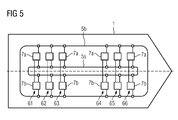
- 5 1 shows, by way of example, a ship 1 with six such pairs 61-66 of higher-level central controls 7a, 7b, for example pair 61 belonging to a drive system, pair 62 to a power generation system and pairs 63-66 to ship operating systems.
- the bus ring 5a runs in the ship's longitudinal direction in the ship's center and the other of the bus rings 5a, 5b, here the bus ring 5b, in the ship's longitudinal direction along the two sides of the ship.
- the bus ring running in the area of the ship's center thus remains intact.
- the central controllers 7a, 7b of all ship systems and numerous components of the subring buses 8 of these ship systems can be constructed from the same type of hardware components.
- the same software base can be used for all of these ship systems, ie a respective same control software base and the same operating software (especially the same visualization images).
- a single engineering system can be used for the configuration and software generation of all ship systems. This also reduces the number of software variants and engineering tools. Uniform communication interfaces between the different ship systems make communication easier and thereby possible the error probability can be reduced. Overall, this also reduces the training and service costs.
- the local operating and monitoring devices 12 of the ship systems can have the same visualization and operating philosophy as the main operating and monitoring devices 6 connected to the main ring bus 5.
- the ship systems can then be controlled and monitored via the local operating and monitoring devices 12 in the same way as via the higher-level operating and monitoring devices.
Landscapes
- Engineering & Computer Science (AREA)
- Computer Networks & Wireless Communication (AREA)
- Signal Processing (AREA)
- Supply And Distribution Of Alternating Current (AREA)
- Safety Devices In Control Systems (AREA)
Applications Claiming Priority (1)
| Application Number | Priority Date | Filing Date | Title |
|---|---|---|---|
| DE102008024491 | 2008-05-21 |
Publications (2)
| Publication Number | Publication Date |
|---|---|
| EP2124394A2 true EP2124394A2 (fr) | 2009-11-25 |
| EP2124394A3 EP2124394A3 (fr) | 2013-06-19 |
Family
ID=40983637
Family Applications (1)
| Application Number | Title | Priority Date | Filing Date |
|---|---|---|---|
| EP09160464.5A Withdrawn EP2124394A3 (fr) | 2008-05-21 | 2009-05-18 | Bateau ayant un système de bateau à deux directions centrales placées avant |
Country Status (1)
| Country | Link |
|---|---|
| EP (1) | EP2124394A3 (fr) |
Cited By (2)
| Publication number | Priority date | Publication date | Assignee | Title |
|---|---|---|---|---|
| CN113726012A (zh) * | 2021-08-31 | 2021-11-30 | 广船国际有限公司 | 一种控制系统及船舶 |
| DE102021212193A1 (de) | 2021-10-28 | 2023-05-04 | Zf Friedrichshafen Ag | Fahrzeugsteuerungssystem und Verfahren, insbesondere für eine E/E-Architektur |
Citations (1)
| Publication number | Priority date | Publication date | Assignee | Title |
|---|---|---|---|---|
| DE102004041824A1 (de) | 2004-08-27 | 2006-03-09 | Siemens Ag | Schiff mit einem Datennetzwerk |
Family Cites Families (2)
| Publication number | Priority date | Publication date | Assignee | Title |
|---|---|---|---|---|
| US7099755B2 (en) * | 2003-05-30 | 2006-08-29 | Siemens Aktiengesellschaft | Automation and platform management system for naval vessels |
| DE102004041820A1 (de) * | 2004-08-27 | 2006-03-09 | Siemens Ag | Schiff mit einem Datennetzwerk |
-
2009
- 2009-05-18 EP EP09160464.5A patent/EP2124394A3/fr not_active Withdrawn
Patent Citations (1)
| Publication number | Priority date | Publication date | Assignee | Title |
|---|---|---|---|---|
| DE102004041824A1 (de) | 2004-08-27 | 2006-03-09 | Siemens Ag | Schiff mit einem Datennetzwerk |
Cited By (2)
| Publication number | Priority date | Publication date | Assignee | Title |
|---|---|---|---|---|
| CN113726012A (zh) * | 2021-08-31 | 2021-11-30 | 广船国际有限公司 | 一种控制系统及船舶 |
| DE102021212193A1 (de) | 2021-10-28 | 2023-05-04 | Zf Friedrichshafen Ag | Fahrzeugsteuerungssystem und Verfahren, insbesondere für eine E/E-Architektur |
Also Published As
| Publication number | Publication date |
|---|---|
| EP2124394A3 (fr) | 2013-06-19 |
Similar Documents
| Publication | Publication Date | Title |
|---|---|---|
| EP2504740B1 (fr) | Module de sécurité pour un appareil d'automatisation | |
| DE69604249T2 (de) | Fehlertolerantes verteiltes Steuerungssystem | |
| EP2301202B1 (fr) | Dispositif de commande et/ou de surveillance et de demande de données à partir d'unités de fonction décentralisées agencées le long d'un réseau de trafic | |
| EP0092719B1 (fr) | Disposition pour le couplage d'unités de traitement numérique | |
| EP2859226B1 (fr) | Système de sécurité pour éolienne | |
| EP1642179B1 (fr) | Dispositif pour commander de maniere automatisee le deroulement d'une operation dans une installation technique | |
| EP3100121B1 (fr) | Procédé et dispositif pour déconnecter en toute sécurité une charge électrique | |
| DE102004055330A1 (de) | Verfahren und Vorrichtung zum Betreiben eines Netzwerkes | |
| EP1782582B1 (fr) | Navire equipe d'un reseau de donnees | |
| DE102015105929A1 (de) | Automatisierungsgerät zum redundanten Steuern eines Busteilnehmers | |
| EP1687681B1 (fr) | Méthode d'opération d'un réseau | |
| DE102006055887A1 (de) | Kommunikationssystem mit einer Master-Slave-Struktur | |
| EP2099164B1 (fr) | Dispositif de sécurité destiné à la commande sécurisée d'actionneurs raccordés | |
| EP2423897B1 (fr) | Installation d'alerte aux dangers et son procédé de fonctionnement | |
| DE102008041463A1 (de) | Steuersystem und Steuerverfahren zum Steuern einer Mehrzahl von Antriebsquellen eines Hybridantriebs | |
| DE102004041824B4 (de) | Schiff mit einem Datennetzwerk | |
| EP4229485A1 (fr) | Dispositif de commande d'un processus de sécurité critique | |
| EP2124394A2 (fr) | Bateau ayant un système de bateau à deux directions centrales placées avant | |
| DE102008038131B4 (de) | Redundantes Steuerungssystem und Verfahren zur sicherheitsgerichteten Ansteuerung von Aktoren | |
| EP2993537A1 (fr) | Diagnostic d'erreurs dans des systèmes d'automatisation | |
| DE19929804B4 (de) | Steuerungssystem | |
| DE102008024489A1 (de) | Schiff mit einem Schiffssystem mit einer zentralen Steuerung | |
| DE102011051629B3 (de) | Sicherheitsbussystem | |
| EP1695158B1 (fr) | Dispositif de transmission de donnees a securite intrinseque | |
| EP3989018B1 (fr) | Dispositif de commande, module de protection pour un tel dispositif et procédé correspondant |
Legal Events
| Date | Code | Title | Description |
|---|---|---|---|
| PUAI | Public reference made under article 153(3) epc to a published international application that has entered the european phase |
Free format text: ORIGINAL CODE: 0009012 |
|
| AK | Designated contracting states |
Kind code of ref document: A2 Designated state(s): AT BE BG CH CY CZ DE DK EE ES FI FR GB GR HR HU IE IS IT LI LT LU LV MC MK MT NL NO PL PT RO SE SI SK TR |
|
| RAP1 | Party data changed (applicant data changed or rights of an application transferred) |
Owner name: SIEMENS AKTIENGESELLSCHAFT |
|
| PUAL | Search report despatched |
Free format text: ORIGINAL CODE: 0009013 |
|
| AK | Designated contracting states |
Kind code of ref document: A3 Designated state(s): AT BE BG CH CY CZ DE DK EE ES FI FR GB GR HR HU IE IS IT LI LT LU LV MC MK MT NL NO PL PT RO SE SI SK TR |
|
| AX | Request for extension of the european patent |
Extension state: AL BA RS |
|
| RIC1 | Information provided on ipc code assigned before grant |
Ipc: H04L 12/46 20060101AFI20130515BHEP Ipc: H04L 12/40 20060101ALI20130515BHEP |
|
| STAA | Information on the status of an ep patent application or granted ep patent |
Free format text: STATUS: THE APPLICATION IS DEEMED TO BE WITHDRAWN |
|
| 18D | Application deemed to be withdrawn |
Effective date: 20131220 |