EP2124508A1 - Einrichtung, system und verfahren zur steuerung einer audiovisuellen umgebung - Google Patents
Einrichtung, system und verfahren zur steuerung einer audiovisuellen umgebung Download PDFInfo
- Publication number
- EP2124508A1 EP2124508A1 EP07860067A EP07860067A EP2124508A1 EP 2124508 A1 EP2124508 A1 EP 2124508A1 EP 07860067 A EP07860067 A EP 07860067A EP 07860067 A EP07860067 A EP 07860067A EP 2124508 A1 EP2124508 A1 EP 2124508A1
- Authority
- EP
- European Patent Office
- Prior art keywords
- illumination
- audio
- illumination device
- visual environment
- data
- Prior art date
- Legal status (The legal status is an assumption and is not a legal conclusion. Google has not performed a legal analysis and makes no representation as to the accuracy of the status listed.)
- Withdrawn
Links
Images






Classifications
-
- H—ELECTRICITY
- H05—ELECTRIC TECHNIQUES NOT OTHERWISE PROVIDED FOR
- H05B—ELECTRIC HEATING; ELECTRIC LIGHT SOURCES NOT OTHERWISE PROVIDED FOR; CIRCUIT ARRANGEMENTS FOR ELECTRIC LIGHT SOURCES, IN GENERAL
- H05B47/00—Circuit arrangements for operating light sources in general, i.e. where the type of light source is not relevant
- H05B47/10—Controlling the light source
- H05B47/155—Coordinated control of two or more light sources
-
- H—ELECTRICITY
- H05—ELECTRIC TECHNIQUES NOT OTHERWISE PROVIDED FOR
- H05B—ELECTRIC HEATING; ELECTRIC LIGHT SOURCES NOT OTHERWISE PROVIDED FOR; CIRCUIT ARRANGEMENTS FOR ELECTRIC LIGHT SOURCES, IN GENERAL
- H05B47/00—Circuit arrangements for operating light sources in general, i.e. where the type of light source is not relevant
- H05B47/10—Controlling the light source
- H05B47/175—Controlling the light source by remote control
- H05B47/198—Grouping of control procedures or address assignation to light sources
- H05B47/199—Commissioning of light sources
Definitions
- the present invention relates to an audio-visual environment control device, an audio-visual environment control system including the audio-visual environment control device, and an audio-visual environment control method, each of which enables production of illumination effects such as improvement in the realistic atmosphere created at the time of observing images by controlling illumination light from an illumination device provided in a predetermined space such as an audio-visual environment space.
- the technique including linked operation of the display and the illumination device achieves a highly realistic atmosphere without a large display, thereby reducing restrictions of costs and installation space, for example.
- the illumination light of the plurality of illumination devices installed in a viewer's room is controlled in color and brightness according to the images displayed on the display.
- This provides the viewer with such a sense and an effect that as if the viewer exists in the image space displayed on the display.
- Patent Literature 1 discloses such a technique in which images displayed on a display and illumination light of an illumination deice are linked to operate together.
- Patent Literature 1 describes a method for producing illumination control data for a plurality of illumination devices according to features (representative color and average brightness) of image data, in an illumination system for controlling the plurality of illumination devices linked to operate with images to be displayed. More specifically, Patent Literature 1 discloses that a display region for detecting the features of the image data varies according to the installation position of each illumination devices.
- Patent Literature 1 discloses that the control data may not only be calculated from the features of the image data, but also be delivered either solely or in combination with the image data via, e.g., the Internet or via carrier waves.
- Patent Literature 1 Japanese Patent Application Publication, Tokukai , No. 2001-343900 A (Publication Date: December 14, 2001 )
- Patent Literature 1 merely generates illumination control data corresponding to a predetermined arrangement of the illumination devices.
- the technique therefore includes no arrangement of detecting the position of each illumination device installed in an audio-visual environment space so that suitable illumination control data corresponding to the detection result is generated. This prevents suitable illumination control, e.g., when an illumination device or an image display device in the audio-visual environment space is moved, or when an additional illumination device is provided.
- the present invention has been accomplished in view of the above problem with the conventional art. It is an object of the present invention to provide an audio-visual environment control device, an audio-visual environment control system, and an audio-visual environment control method, each of which allows suitable illumination control even when, for example, the installation position of an illumination device is changed or when an additional illumination device is provided, and also achieves a suitable illumination effect (e.g., a highly realistic atmosphere).
- a suitable illumination effect e.g., a highly realistic atmosphere.
- the present invention solves the above problem with the following technical means:
- the present invention provides an audio-visual environment control device for controlling illumination light from at least one illumination device in accordance with features of image data to be displayed by a display device
- the audio-visual environment control device including: illumination device position detecting means for detecting each installation position of the at least one illumination device; storing means for storing information on the each installation position detected by the illumination device position detecting means; and illumination data generating means for generating, in accordance with features of image data, illumination control data for controlling each of the at least one illumination device, the features being extracted in accordance with the information stored by the storing means.
- the present invention provides an audio-visual environment control device for controlling, in accordance with features of an image to be displayed by a display device, illumination light from at least one illumination device provided in an audio-visual space in which the display device is provided, the audio-visual environment control device including: illumination device position detecting means for detecting each installation position of the at least one illumination device; and illumination data generating means for (i) extracting features in a partial region of an image, the partial region corresponding to the each installation position detected by the illumination device position detecting means and (ii) generating illumination control data for controlling each of the at least one illumination device in accordance with the features thus extracted.
- the present invention provides an audio-visual environment control device for controlling illumination light from at least one illumination device in accordance with (i) reference data, obtained from an external device, on an illumination device position in a virtual audio-visual environment space and (ii) illumination control data, obtained from an external device, corresponding to the illumination position in the virtual audio-visual environment space
- the audio-visual environment control device including: illumination device position detecting means for detecting each installation position of the at least one illumination device; storing means for storing information on the each installation position detected by the illumination device position detecting means; and illumination data converting means for converting, in accordance with (i) the information stored in the storing means and (ii) the reference data, the illumination control data into illumination control data for controlling each of the at least one illumination device.
- the present invention provides an audio-visual environment control device, including: receiving means for receiving, (i) reference data indicating an arrangement in which at least one illumination device is provided in a virtual space and (ii) illumination control data for controlling illumination light from each of the at least one illumination device having the arrangement indicated by the reference data, so as to cause the reference data and the illumination control data to be correlated with each other; illumination device position detecting means for detecting a position of an illumination device provided in an actual space; and illumination control data converting means for converting the illumination control data received by the receiving means so that an illumination effect, similar to an illumination effect that is obtained in a case where the illumination light from each of the at least one illumination device having the arrangement indicated by the reference data received by the receiving means is controlled, is obtained in a case where the illumination device is provided at the position detected by the illumination device position detecting means.
- the present invention provides an audio-visual environment control device for controlling illumination light from at least one illumination device in accordance with illumination control data obtained from an external device, the audio-visual environment control device including: illumination device position detecting means for detecting each installation position of the at least one illumination device; sending means for sending, to the external device, information on the each installation position detected by the illumination device position detecting means; and receiving means for receiving illumination control data generated by the external device in accordance with the information on the each installation position of the at least one illumination device.
- the present invention provides an audio-visual environment control method for controlling illumination light from at least one illumination device in accordance with features of image data to be displayed by a display device, the audio-visual environment control method including the steps of: (i) detecting each installation position of the at least one illumination device; (ii) storing information on the each installation position detected in the step (i); and (iii) generating, in accordance with features of image data, illumination control data for controlling each of the at least one illumination device, the features being extracted in accordance with the information on the each installation position, the information being stored in the step (ii).
- the present invention provides an audio-visual environment control method for controlling illumination light from at least one illumination device in accordance with (i) reference data, obtained from an external device, on an illumination device position in a virtual audio-visual environment space and (ii) illumination control data, obtained from an external device, corresponding to the illumination position in the virtual audio-visual environment space, the audio-visual environment control method including the steps of: (i) detecting each installation position of the at least one illumination device; storing information on the each installation position detected in the step (i); and (iii) converting, in accordance with (a) the information stored in the step (ii) and (b) the reference data, the illumination control data, into illumination control data for controlling each of the at least one illumination device.
- the present invention provides an audio-visual environment control method for controlling illumination light from at least one illumination device in accordance with illumination control data obtained from an external device, the audio-visual environment control method comprising the steps of: (i) detecting each installation position of the at least one illumination device; sending means for sending, to the external device, information on the each installation position detected in the step (i); and (iii) receiving illumination control data generated by the external device in accordance with the information on the each installation position of the at least one illumination device.
- the present invention allows automatic detection of the installation position of at least one illumination device in an audio-visual environment space and also allows generation of the most suitable illumination control data corresponding to the above-detected installation position of the illumination device.
- suitable illumination control e.g., in the case where the installation position of an illumination device in the audio-visual environment is changed, or in the case where an additional illumination device is provided.
- Audio-visual environment control devices and audio-visual environment control systems according to the embodiments of the present invention will be described with reference to Figs. 1 through 19 .
- Fig. 1 is a block diagram illustrating an audio-visual environment control device according to a first embodiment of the present invention.
- the audio-visual environment control device 1 of the present embodiment causes a receiving section 2 to receive broadcast data sent from a sender (broadcast station) and also causes a data separating section 3 to separate the broadcast data into image data and sound data, which are multiplexed in the broadcast data.
- the image data and the sound data obtained as a result of the separation by the data separating section 3 are sent to an image display device 4 and a sound reproduction device 5, respectively.
- an illumination device position detecting section (illumination device position detecting means) 6 receives illumination light from at least one illumination device 7 installed in an audio-visual environment space and labeled in advance with an identifier (hereinafter referred to as "ID"), detects the installation position of each illumination device 7 on the basis of the illumination light, and sends data (illumination device position data) on the thus-detected installation position of each illumination device 7 to an illumination device position table 8.
- the illumination device position table 8 stores the illumination device position data in a table format by ID of each illumination device 7.
- the illumination device position data stored in the illumination device position table 8 is sent to an illumination control data generating section (illumination data generating means) 9 in accordance with instructions from the illumination control data generating section 9.
- the illumination control data generating section 9 generates suitable illumination control data corresponding to the installation position of each illumination device 7, from the image data and the sound data obtained as a result of the separation by the data separating section 3 as well as the illumination device position data read from the illumination device position table 8 and corresponding to each illumination device 7.
- the illumination control data generating section 9 then sends the above-generated illumination control data to each illumination device 7.
- the illumination control data to be sent to each illumination device 7 needs to have an output timing synchronous with the respective output timings of the image data and the sound data.
- the audio-visual environment control device 1 includes, for example, delay generating sections 10a and 10b for respectively delaying the image data and the sound data obtained as a result of the separation by the data separating section 3, for a period of time necessary for the illumination control data generating section 9 to generate the illumination control data. This allows the respective output timings of the image data and the sound data to be synchronous with the output timing of the illumination control data.
- the audio-visual environment control device 1 is an audio-visual environment control device that controls, on the basis of the feature of each image displayed by the image display device 4, illumination from at least one illumination device 7 provided in an audio-visual space in which the image display device 4 is provided.
- the audio-visual environment control device 1 also includes (i) the illumination device position detecting section 6 for detecting the installation position of each illumination device 7 and (ii) the illumination control data generating section 9 for generating illumination control data for controlling each illumination device 7.
- the illumination control data refers, specifically, to data for individually controlling the respective illuminations from multiple illumination devices 7, e.g., data (control signal) for controlling, for example, the color and light intensity (luminance) of the illumination from each illumination device 7.
- the illumination device position table 8 may also be considered as a storing section (storing means) storing an illumination device position table.
- the above arrangement allows the audio-visual environment control device to suitably control at least one illumination device 7 installed in an audio-visual environment space, in accordance with the installation position of each illumination device 7. Further, the above arrangement allows suitable illumination control in any case: e.g., in the case where an illumination device 7 is reinstalled at a different position in the audio-visual environment space; in the case where an additional illumination device 7 is provided; or even in the case where the image display device 4 is moved to a different position.
- the audio-visual environment control device 1 may be provided integrally with the image display device 4 and the sound reproduction device 5. Alternatively, they may be provided separately.
- Fig. 2 is an external view illustrating an example of the illumination devices 7 used in the present embodiment. As mentioned above, the illumination devices 7 are labeled with their respective unique IDs for individually identifying each of the multiple illumination devices 7.
- Each of the illumination devices 7 illustrated in Fig. 2 includes, for example, LED light sources of red (R), green (G), and blue (B) disposed at regular intervals and individually controllable for light emission.
- Each of the illumination devices 7 uses its LED light sources of the three primary colors so as to emit illumination light having a desired color and luminance.
- the illumination devices 7 may have any arrangement, provided that the arrangement allows the illumination devices 7 to control the color and brightness of the ambient light around the image display device 4.
- Each illumination device 7 may include white LEDs and color filters instead of the combination of the LED light sources emitting lights of the above predetermined colors.
- each illumination device 7 may include, for example, the combination of white lamps or fluorescent tubes and color filters, or color lamps.
- the illumination devices 7 are not necessarily illumination devices of a variable color type; alternatively, each illumination device 7 may, for example, include white lamps or fluorescent tubes so that only the luminance of white light is variably controlled for each illumination device 7. This also allows achievement of a highly realistic atmosphere as compared to the case in which the luminance of the illumination light is fixed.
- Fig. 3 is an explanatory view illustrating an example of an audio-visual environment space.
- the audio-visual environment space contains the image display device 4 and seven illumination devices 7 installed therein.
- the illumination device 7a is the type of illumination device that is installed on the ceiling, whereas each of the illumination devices 7b through 7g is the type of illumination device that is portably installed.
- the arrangement and number of the illumination devices 7a through 7g vary according to the audio-visual environment space for each viewer. They also vary, even in the same audio-visual environment space, e.g., when the illumination devices 7 are moved, when an additional illumination device 7 is provided, and/or when any of the illumination devices 7 is removed, for room rearrangement, for example.
- moving the image display device 4 changes the relative position of each illumination device 7 with respect to the image display device 4.
- the respective installation positions and number of the illumination devices 7 in the audio-visual environment space vary according to each viewer, and they also vary, even for the same viewer, because of room rearrangement, for example.
- Constantly controlling the illumination devices 7 in a suitable manner for achievement of a highly realistic atmosphere even in the above case requires detecting the position of each illumination device installed in the audio-visual environment space and thereby controlling its illumination in accordance with the position detected.
- the following describes a method of individually detecting the respective installation positions of the illumination devices in an audio-visual environment space so that their illuminations are suitably controlled in accordance with the detection result.
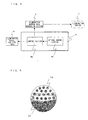
- Fig. 4 is a functional block diagram illustrating the arrangement of the illumination device position detecting section 6 in Fig. 1 .
- the illumination device position detecting section 6 includes an optical sensor 6a and a control section 6b.
- the optical sensor 6a is, for example, a photo sensor capable of detecting the direction and intensity of incident light.
- the optical sensor 6a includes multiple light-receiving elements 14 disposed in half of the region of the spherical surface, so that the optical sensor 6a has a mechanism for receiving light incident in many directions.
- the optical sensor 6a is preferably provided on the image display device 4 as illustrated in Fig. 3 . This is because suitably controlling the illumination from each illumination device in an audio-visual environment space requires data on the relative positional relationship between the image display device 4 and each illumination device 7.
- the disposition of the optical sensor 6a on the image display device 4 eliminates the need to detect the position of the image display device 4 with use of the optical sensor 6a.
- the optical sensor 6a only needs to detect the position of each illumination device 7 so as to detect the relative position of each illumination device 7 with respect to the image display device 4.
- the control section 6b detects the installation position of each illumination device 7 on the basis of the intensity and direction of light detected by the optical sensor 6a. Specifically, the control section 6b estimates the distance between the optical sensor 6a and a specific illumination device 7 on the basis of the largest quantity of light among the respective quantities of light detected by the multiple light-receiving elements 14 and also estimates that the specific illumination device 7 is present in the direction faced by a specific one of the light-receiving elements 14 that has detected the largest quantity of light, whereby the control section 6b determines the relative position of the specific illumination device 7 with respect to the optical sensor 6a. In the present embodiment, the control section 6b determines the installation position of each illumination device 7 in the form of a vector with the position of the optical sensor 6a being the origin and sends the thus-determined vector data to the illumination device position table 8.
- Fig. 6 is a view illustrating a flow of the operation of detecting illumination device positions and generating an illumination device position table in connection with Fig. 1 .
- the illumination control data generating section 9 supplies to the illumination devices illumination control data (e.g., in the case of performing drive control of the respective tones of the LED light sources of R, G, and B each in units of 8 bits and n being 1, ID1 (255, 255, 255), ID2 (0, 0, 0), ID3 (0, 0, 0), ..., IDn (0, 0, 0)) according to the command (Step 2). Successively supplying such illumination control data turns on each designated IDn illumination device at the highest luminance and turns off the other illumination devices (Step 3).
- the illumination control data e.g., in the case of performing drive control of the respective tones of the LED light sources of R, G, and B each in units of 8 bits and n being 1, ID1 (255, 255, 255), ID2 (0, 0, 0), ID3 (0, 0, 0), ..., IDn (0, 0, 0)
- the optical sensor 6a determines whether it receives illumination light from each designated IDn illumination device (Step 4).
- the control section 6b determines the installation position of the specific IDn illumination device on the basis of the intensity and direction of the illumination light received by the optical sensor 6a (Step 5).
- the control section 6b writes the thus-determined illumination device position data to an address in the illumination device position table 8, the address corresponding to the specific IDn illumination device (Step 6).
- the control section 6b determines whether or not such a state has continued for a predetermined period of t seconds (Step 7).
- the optical sensor 6a repeats the operation of detecting illumination light according to Step 4 until t seconds elapse.
- Step 8 it is determined whether or not the respective positions of the illumination devices of all IDs have been detected.
- Step 8 it is determined that the respective positions of the illumination devices of all IDs have been detected.
- Step 8 one is added to the value of n and then the control section 6b supplies a command so that the installation position of the subsequent IDn+1 illumination device is detected (Step 9).
- control section 6b sends a command to the illumination control data generating section 9 to turn only on ID2 illumination device and to turn off the other illumination devices.
- control section 6b determines illumination device position data for ID2 illumination device and writes the thus-determined illumination device position data to an address in the illumination device position table 8, the address corresponding to ID2 illumination device.
- Step 7 When it is detected that the optical sensor 6a receives no illumination light from a specific IDn illumination device for t seconds in Step 7, it is determined that the specific IDn illumination device does not exist in the audio-visual environment space. Then, one is added to the value of n, and the control section 6b supplies a command so that the installation position of the subsequent IDn+1 illumination device is detected (Step 9). Performing the above-described series of steps as many times as the number of illumination devices installed results in the respective installation positions of all the illumination devices being stored in the illumination device position table 8 in association with their corresponding IDs.
- the illumination control data includes a 6-bit ID followed by three sets of 8-bit control data for controlling the illumination device having the ID, the three sets corresponding to red (R), green (G), and blue (B), respectively.
- Each illumination device compares the ID given to itself with the ID included in the illumination control data so as to obtain control data added to the ID of its own. This allows each illumination device to emit its desired illumination light.
- the above-described operation of detecting illumination device positions starts with storing the intensity and direction of light that is detected by the optical sensor 6a while all the illumination devices 7 are off, the intensity with regard to the direction being later subtracted from a detection result obtained in Step 4. This eliminates the influence of external light other than the illumination light from the illumination devices 7, thereby allowing a more precise operation of detecting illumination device positions.
- the illumination device position table 8 stores, in a table format as illustrated in Fig. 7 , illumination device position data sent from the control section 6b.
- Fig. 8 is a view illustrating a flow of the operation by the illumination control data generating section 9.
- the illumination control data generating section 9 reads, in units of one frame, the image data obtained as a result of the separation by the data separating section 3 in Fig. 1 (Step 1).
- the illumination control data generating section 9 refers to data on the position of each illumination device, stored in the illumination device position table 8, so as to determine, for each illumination device, a screen region in which the image feature is to be detected (Step 2).
- the illumination control data generating section 9 then detects the feature in the above-determined screen region for the image data for one frame read in Step 1 (Step 3).
- the feature of the image data may be determined using, for example, color signals or luminance signals, as well as ambient color temperatures obtained at the time of shooting the image.
- the illumination control data generating section 9 detects not only the feature of the image data, but also that of the sound data.
- the feature of the sound data may be determined using, for example, volumes or audio frequencies.
- the illumination control data generating section 9 generates illumination control data for each illumination device, from the image feature and/or the sound feature detected as above (Step 4).
- the illumination control data generating section 9 may determine the average of the image features in the screen regions corresponding to the respective installation positions of the illumination devices, the installation positions being detected by the illumination device position detecting section 6, so as to generate illumination control data from the above-determined average.
- the method of generating illumination control data is clearly not limited to obtaining the average of the image features and therefore may be any other determination method.
- the illumination control data generating section 9 determines partial regions of an image displayed by the image display device 4, the partial regions corresponding to the installation positions of the illumination devices 7, the installation positions being detected by the illumination device position detecting section 6, so as to extract the respective image features in the thus-determined partial regions.
- the illumination control data generating section 9 then performs a predetermined operation on the thus-extracted features so as to generate illumination control data corresponding to the values obtained through the operation, as illumination control data for controlling each illumination device 7.
- the illumination control data generated by the illumination control data generating section 9 and the image data and the sound data for the frame corresponding to the illumination control data are sent, in synchronization with each other, to each illumination device 7, the image display device 4, and the sound reproduction device 5, respectively.
- the illumination control data generating section 9 determines whether or not a subsequent frame is to be supplied, i.e., whether or not the supplying of image data has ended (Step 5).
- the illumination control data generating section 9 reads this subsequent frame (Step 1).
- the processing operation is ended. Sequentially repeating the above steps allows performance of illumination control suitable for the display image for each image frame.
- Step 2 The following describes a manner of determining a target region for detection of the feature according to Step 2.
- the image data (one frame) read represents an image of a setting sun as illustrated in Fig. 10 .
- the image data of Fig. 10 is bright in the region corresponding to the image of the sun and becomes gradually darker as farther away from the image of the sun toward its surrounding region. This makes it preferable to detect the image features in the feature detection regions illustrated in Fig. 11 , the regions corresponding to the respective positions of the illumination devices.
- the determination of feature detection regions starts with determination of such regions with respect to the x direction, followed by determination of them with respect to the y direction.
- the feature detection regions for the illumination devices are finally determined based on the respective feature detection regions determined with respect to the x direction and the y direction.
- the illumination devices installed in the audio-visual environment space illustrated in Fig. 9 can be grouped, for each set of illumination devices having an identical position with respect to the x direction, into three columns: the illumination devices v1, v4, and v7 positioned to the left of a viewer facing the screen; the illumination devices v2, v5, and v8 positioned in the middle; and the illumination devices v3, v6, and v9 positioned to the right of a viewer facing the screen (hereinafter referred to as "left illumination device column”, “middle illumination device column”, and "right illumination device column”, respectively).
- the left illumination device column has its feature detection regions in the left screen portion of the image data.
- the middle illumination device column has its feature detection regions in the middle screen portion of the image data.
- the right illumination device column has its feature detection regions in the right screen portion of the image data.
- the columnar position of each illumination device determines its feature detection region with respect to the x direction of the display screen of the image display device 4.
- the illumination control data generating section 9 determines the feature detection regions with respect to the y direction of the display screen of the image display device 4.
- the feature detection regions with respect to the y direction need to be suitably determined based on such data as the content (e.g., luminance distribution, color distribution, histogram) or category of an image displayed by the image display device 4, or on the combination of them.
- the feature detection regions may be determined based on an indicator selected from a large number of indicators, among which the most suitable one is used according to need.
- the feature detection regions of the image illustrated in Fig. 10 are determined using the content (i.e., luminance distribution) of the display image as an indicator for the determination of the feature detection regions.
- Fig. 10 illustrates an image of the sun setting in the sea.
- the image of the sun displayed at the central portion of the image screen has the highest luminance.
- the luminance of the image on the screen becomes continuously lower as farther away from the image of the sun toward its surrounding region.
- the illumination devices installed in the audio-visual environment space illustrated in Fig. 9 can be grouped, for each set of illumination devices having an identical position with respect to the y direction, into three rows: the illumination devices v1, v2, and v3 positioned closest to the screen; the illumination devices v4, v5, and v6 positioned so as to face the screen across the illumination devices v1, v2, and v3; and the illumination devices v7, v8, and v9 positioned farthest from the screen (hereinafter referred to as "closest illumination device row”, “middle illumination device row”, and "farthest illumination device row”, respectively).
- the closest illumination device row is installed closest to the image display device 4, which indicates that it is positioned farthest in the direction of the image display device 4 from a viewer.
- the closest illumination device row requires the closest illumination device row to produce illumination light on the basis of the color and brightness of a portion of the display image, the portion displaying a spot far from the shooting spot.
- the closest illumination device row needs to have its feature detection regions in a portion of the display image, the portion corresponding to the horizon.
- producing illumination light with the closest illumination device row in accordance only with the image feature in the portion corresponding to the horizon would cause the illumination light to have too high a luminance and thereby cause the display image in the portion corresponding to the horizon to lose continuity with the display image in an upper portion of the screen. This would result in an inharmonious display image.
- the illumination devices v1, v2, and v3 are set to have their respective feature detection regions collectively including the horizon in their central portions as well as a large portion adjacent to the horizon.
- the farthest illumination device row is positioned farthest from the image display device 4 and is a row of illumination devices positioned, for example, directly above a viewer.
- the farthest illumination device row needs to produce illumination light on the basis of the color and brightness of a portion of the display image, the portion displaying a spot closest to the shooting spot.
- the closest illumination device row needs to have its feature detection regions in a portion of the display image, the portion being the uppermost portion of the image of the sky.
- the farthest illumination device row needs to reproduce the space of the shooting spot.
- the illumination devices v7, v8, and v9 are set to have small feature detection regions so as to reproduce the color and brightness of the sky directly above the shooting spot. This effectively allows improvement in the realistic atmosphere.
- the middle illumination device row may play a role intermediate between the closest illumination device row and the farthest illumination device row described above. Specifically, in the case of the image in Fig. 10 , the middle illumination device row needs to have its feature detection regions in a portion of the display image, the portion being a portion of the sky, positioned between the horizon and the portion of the sky directly above the shooting spot. Thus, as illustrated in (d) through (f) in Fig. 11 , the illumination devices v4, v5, and v6 may be set to have their respective feature detection regions between those of the closest illumination device row and those of the farthest illumination device row.
- Setting image feature detection regions in accordance with the respective installation positions of the illumination devices as described above allows, when the image in Fig. 10 is displayed, effective control of the illumination light from each illumination device installed around the image display device 4 and thereby provides a viewer with a highly realistic atmosphere.
- the method of determining image feature detection regions is not necessarily limited to the one described above. The determination method may vary, for example, according to the category of the image.
- the above embodiment describes detecting the image feature and/or the sound feature for each frame, for generation of illumination control data.
- the illumination control data generating section 9 may perform its control such that the image feature and/or the sound feature are/is detected for each scene or shot so that the illumination light from each illumination device 7 is substantially maintained for a particular scene or shot in the story.
- the above embodiment describes generating illumination control data for each illumination device on the basis of the feature and/or sound data of image data received by the image receiving device.
- the method used in the present invention is not limited to this.
- illumination device position data representing the installation position of each illumination device in a certain virtual audio-visual environment space
- illumination control data for each illumination device in such a virtual audio-visual environment space both of which are, for example, multiplexed in broadcast waves solely or in combination with image data.
- a predetermined conversion process may be provided to the received illumination control data on the basis of (i) the received audio-visual environment reference data and (ii) illumination device position data stored in the illumination device position table. This allows generation of illumination control data for each illumination device installed in the audio-visual environment space for a viewer.
- This is described below as the second embodiment of the present invention. It should be noted that identical members between the first and second embodiments are represented by the same reference numerals and that the description of such members is omitted.
- Fig. 12 is a block diagram illustrating an audio-visual environment control device according to the second embodiment of the present invention.
- the audio-visual environment control device (illumination control device) 21 of the present embodiment causes a receiving section 22 to receive broadcast data sent from a sender (broadcast station) and also causes a data separating section 23 to separate the broadcast data into image data, sound data, illumination control data, and audio-visual environment reference data, which are all multiplexed in the broadcast data.
- the image data and the sound data obtained as a result of the separation by the data separating section 23 are sent to an image display device 4 and a sound reproduction device 5, respectively.
- the illumination control data and the audio-visual environment reference data are sent to an illumination control data converting section (illumination data converting means) 29.
- the audio-visual environment reference data refers to data indicating the installation position of at least one illumination device provided in a predetermined virtual space (e.g., an audio-visual environment space in which an image display device is provided).
- the illumination control data refers to data for individually controlling the illumination from each illumination device provided in the virtual space, e.g., data for controlling, for example, the color and light intensity (luminance) of the illumination from each illumination device.
- the illumination control data includes data for specifying each target illumination device (e.g., the ID of each illumination device) and control values for controlling the illumination from each illumination device.
- the audio-visual environment reference data and the illumination control data are associated with each other: the illumination control data indicates the control values for controlling the illuminations from the illumination devices installed at positions indicated by the audio-visual environment reference data.
- an illumination device position detecting section 6 receives illumination light from at least one illumination device 7 installed in an audio-visual environment space and labeled in advance with an identifier (hereinafter referred to as "ID"), detects the installation position of each illumination device 7 on the basis of the illumination light, and sends data (illumination device position data) on the thus-detected installation position of each illumination device 7 to an illumination device position table 8.
- the illumination device position table 8 stores the illumination device position data in a table format by ID of each illumination device 7.
- the illumination device position data stored in the illumination device position table 8 is sent to an illumination control data converting section 29 in accordance with instructions from the illumination control data converting section 29.
- the illumination control data converting section 29 converts the illumination control data obtained as a result of the separation by the data separating section 23 into suitable illumination control data corresponding to the position of each illumination device 7 installed in the audio-visual environment space.
- the illumination control data converting section 29 then sends to each illumination device 7 the illumination control data obtained through the above conversion.
- the illumination control data (post-conversion illumination control data) to be sent to each illumination device 7 needs to have an output timing synchronous with the respective output timings of the image data and the sound data.
- the audio-visual environment control device 21 includes, for example, delay generating sections 30a and 30b for respectively delaying the image data and the sound data obtained as a result of the separation by the data separating section 23, for a period of time necessary for the illumination control data converting section 29 to generate the illumination control data. This allows the respective output timings of the image data and the sound data to be synchronous with the output timing of the illumination control data.
- the operation by the illumination device position detecting section 6 is the same as that in the first embodiment described above. The description of the operation is therefore omitted here.
- the illumination control data converting section 29 performs an interpolation operation on the illumination control data and the audio-visual environment reference data, both obtained from an external device, so as to determine illumination control data (post-conversion illumination control data) for controlling the brightness and color of the illumination light to be emitted by each illumination device in the actual audio-visual environment space.
- the illumination control data converting section 29 refers to the illumination device position table so as to obtain the illumination device position data indicating the position of each illumination device 7 provided in the actual audio-visual environment space.
- the illumination control data converting section 29 then converts the illumination control data received by the receiving section 22 into illumination control data (i.e., the illumination control data converting section 29 generates such illumination control data) so that the illumination devices 7 having their respective actual positions (i.e., the respective positions of the illumination devices 7, detected by the illumination device position detecting section 6) produce an illumination effect similar to the illumination effect that would be obtained in the case of controlling the illuminations from the illumination devices provided at the positions indicated by the audio-visual environment reference data received by the receiving section 22.
- the illumination control data converting section 29 controls the illumination devices 7 with use of post-conversion illumination control data corresponding to each illumination device 7 (more specifically, by sending the post-conversion illumination control data to each corresponding illumination device 7).
- the audio-visual environment control device 21 thus has the function as an illumination control device for controlling the illumination devices provided in the actual audio-visual environment space.
- Arranging the audio-visual environment control device as described above eliminates the need to provide the function of generating illumination control data from the image feature and/or the sound feature, and also allows suitably controlling at least one illumination device 7 installed in an audio-visual environment space, in accordance with the installation position of each illumination device 7. Further, the above arrangement allows suitable illumination control in any case; e.g., in the case where an illumination device 7 is reinstalled at a different position in the audio-visual environment space or in the case where an additional illumination device 7 is provided.
- the following describes three methods of converting illumination control data by the illumination control data converting section 29.
- the first method is summarized as follows: when the respective coordinate systems of (i) the virtual audio-visual environment space indicated by the audio-visual environment reference data and (ii) the actual audio-visual environment space for a viewer are, for example, superposed to form a three-dimensional coordinate system with its origin being the center of the screen of the display device, illumination control data is generated on the basis of a region of the walls of the virtual audio-visual environment space, the region being a region onto which light from each illumination device installed in the actual audio-visual environment space is projected.
- Fig. 13 is a view illustrating a virtual audio-visual environment space (audio-visual environment reference data), which contains illumination devices v1' through v8' provided in the eight corners, respectively.
- the respective three-dimensional positions of the illumination devices v1 through v8 are desirably defined by coordinates of the x axis, the y axis, and the z axis in a three-dimensional coordinate space with the center of the screen of an image display device 101 being the origin (0, 0, 0).
- the y axis is desirably defined as coincident with a normal line of the screen of the image display device 101.
- each divisional region is assigned illumination control data for its closest illumination device.
- the three regions (S3, S6, S9) adjacent to the illumination device v3 in Fig. 13 are assigned the illumination control data for the illumination device v3.
- Fig. 14 is a view illustrating the virtual audio-visual environment space, in which illumination devices (v10, v11) installed in the actual audio-visual environment space are positioned.
- the regions T1 and T2 in Fig. 14 are regions of the walls, the regions being irradiated by the illumination devices (v10, v11), respectively.
- each of the irradiation regions T1 and T2 may be determined by the audio-visual environment control device 21 on the basis of data entered by a user so that the area thus determined is stored in a storing section (not shown) available to the illumination control data converting section 9.
- the area of each of the irradiation regions T1 and T2 may be determinable by: placing each illumination device 7 for actual use at a position a certain distance away from the wall; turning on each illumination device 7 with a certain light intensity; and actually measuring a region of the wall, the region being irradiated by each illumination device 7.
- the area of each of the irradiation regions T1 and T2 may be determined as follows: A user enters the specifications and the irradiation direction of each illumination device 7 into the audio-visual environment control device 21. Then, the audio-visual environment control device 21 performs a predetermined operation on the basis of the entered data so as to determine the area of each of the irradiation regions T1 and T2. The area of each of the irradiation regions T1 and T2 may be determined at a timing not particularly limited, provided that it is determined before broadcast data is received.
- the illumination control data converting section 9 determines which regions (among the regions S1 through S24) in the virtual audio-visual environment space correspond to each of the irradiation regions T1 and T2. The illumination control data converting section 9 then controls each of the illumination devices (v10, v11) installed in the actual audio-visual environment space, with use of the control values respectively assigned to the above-determined regions, the control values given to the corresponding illumination devices installed in the virtual audio-visual environment space.
- Fig. 15 illustrates an example of a region in the virtual audio-visual environment space, the region corresponding to the irradiation region T1.
- the illumination control data converting section 29 performs an operation based on the illumination control data (R, G, B) for each of the illumination devices v1' (provided with the illumination value for the region S5) and v3' (provided with the illumination value for the region S6) in accordance with the above-set weights so as to determine illumination control data (R, G, B) for the illumination device v10.
- the illumination control data converting section 29 performs the above operation also with respect to the other illumination device v11 in the actual audio-visual environment space. This results in generation of illumination control data for all the illumination devices installed in the actual audio-visual environment space.
- illumination control data externally obtained is attached to each frame of image data
- the illumination control data conversion process is repeatedly performed for each frame. This allows generation of suitable illumination control data according to images displayed on the image display screen.
- illumination control data is converted on the basis of an irradiation region of the wall in the virtual audio-visual environment space. This allows suitable illumination control even when an illumination device installed in the actual audio-visual environment space produces indirect lighting.
- the illumination control data converting section 29 with use of audio-visual environment reference data and illumination control data corresponding to the audio-visual environment reference data, both received by the receiving section 22, assigns the illumination control data to each of the divisional regions formed by division, into multiple regions, of each wall three-dimensionally surrounding the virtual audio-visual environment space. For example, the illumination control data converting section 29 determines that illumination control data for the illumination device closest to a certain divisional region is the illumination control data for such a divisional region.
- the illumination control data converting section 29 then obtains irradiation region data indicating the area (and the shape) of the region irradiated by the illumination device 11 (e.g., T1) and the above-described illumination device position data.
- the illumination control data converting section 29 thereby determines the area ratio between the divisional regions that are included in the irradiation region when the region indicated by the irradiation region data and irradiated from the position indicated by the illumination device position data is superposed upon the divisional regions.
- the illumination control data converting section 9 performs a weighting operation of the illumination control data for each divisional region with use of the above-determined area ratio. This allows determination of illumination control data for the illumination device 7 causing the irradiation region, on the basis of the above-weighted illumination control data for each divisional region.
- the illumination control data converting section 9 determines the light intensity in the above irradiation region by, for example, totaling up the respective light intensities in the divisional regions, the light intensities being weighted based on the area ratio between the respective portions of the divisional regions, included in the irradiation region.
- the second conversion method is summarized as follows: when the respective coordinate systems of (i) the virtual audio-visual environment space indicated by the audio-visual environment reference data and (ii) the actual audio-visual environment space for a viewer are, for example, superposed to form a three-dimensional coordinate system with its origin being the center of the screen of the display device, illumination control data for controlling each illumination device installed in the actual audio-visual environment space is generated on the basis of the positional relationship between each illumination device installed in the actual audio-visual environment space and the illumination devices installed in the virtual audio-visual environment space.
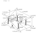
- Fig. 16 is a view illustrating a space model similar to the virtual audio-visual environment space model (containing the eight illumination devices v1' through v8' provided in the eight corners, respectively) used in the above first conversion method.
- the view of Fig. 16 illustrates how illumination devices v1 through v7 installed in the actual audio-visual environment space are positioned.
- the respective three-dimensional positions of the illumination devices are desirably defined by coordinates of the x axis, the y axis, and the z axis in a three-dimensional coordinate space with the center of the screen of an image display device 101 being the origin (0, 0, 0).
- the y axis is desirably defined as coincident with a normal line of the screen of the image display device 101.
- Illumination control data for controlling the illumination device v1 (x1, y1, z1) in Fig. 16 installed in the actual audio-visual environment space is determined based on the illumination control data for each of the illumination devices v1', v3', v5', and v7' installed at the four corners of the wall of the virtual audio-visual environment space, the wall being positioned closest to the illumination device v1.
- the distance between the illumination device v1 and each of the illumination devices v1', v3', v5', and v7' is determined so that the proportions of the respective reciprocals of the distances are obtained.
- the illumination devices v1', v3', v5', and v7' are weighted with respect to the illumination device v1 in accordance with the proportions of the reciprocals.
- the illumination control data converting section 29 performs an operation based on the illumination control data (R, G, B) for each of the illumination devices v1', v3', v5', and v7' in accordance with the above-set weights so as to determine illumination control data (R, G, B) for the illumination device v1.
- the illumination control data converting section 29 performs the above operation also with respect to the other illumination devices v2, v3, v4, v5, v6, v7, and v8 in the actual audio-visual environment space. This results in generation of illumination control data for all the illumination devices installed in the actual audio-visual environment space.
- the illumination control data converting section 29 determines, in a space formed by superposing (i) the coordinate system indicated by illumination device position data stored in the illumination device position table 8 upon (ii) the coordinate system indicated by audio-visual environment reference data, the distance between one of the illumination devices (i.e., first illumination device) indicated by the illumination device position data and each of multiple illumination devices (i.e., second illumination devices) indicated by the audio-visual environment reference data, the multiple illumination devices being positioned in the vicinity of the first illumination device (or having a predetermined positional relationship to the first illumination device).
- the illumination control data converting section 29 then performs a weighting operation on the values of the illumination control data corresponding to each second illumination device with use of the above-determined distances.
- the illumination control data converting section 29 thus determines the value of illumination control data corresponding to the first illumination device, on the basis of the weighted values of the illumination control data.
- illumination control data externally obtained is attached to each frame of image data
- the illumination control data conversion process is repeatedly performed for each frame. This allows generation of suitable illumination control data according to images displayed on the image display screen.
- the present conversion method determines illumination control data for a specific illumination device installed in the actual audio-visual environment space, on the basis of the illumination control data corresponding to each of the four illumination devices provided on the surface of the wall in the virtual audio-visual environment space, the wall being positioned closest to the specific illumination device.
- illumination control data for a specific illumination device may, for example, be determined based on the illumination control data for each of all the eight illumination devices installed in the eight corners of the virtual audio-visual environment space.
- illumination control data for each illumination device installed in the actual audio-visual environment space may also be determined by performing a predetermined interpolation operation on the illumination control data for each of two or more nearby illumination devices in the virtual audio-visual environment space.
- the third conversion method described below is an easy method of generating illumination control data, as compared to the above two methods. This method segments a target space into blocks in correspondence with the illumination devices installed in the virtual audio-visual environment space and generates illumination control data on the basis of which block contains each specific illumination device installed in the actual audio-visual environment space.
- Fig. 18 is a view illustrating a virtual audio-visual environment space containing eight illumination devices v1' through v8' in its eight corners, respectively, as in the virtual audio-visual environment space model used in the above two conversion methods.
- This method segments the virtual audio-visual environment space into eight spaces (blocks).
- Each of the eight blocks is assigned the illumination value of one of the illumination devices v1' through v8', the one being installed in its corner.
- the block designated as B1 in Fig. 18 is, for example, assigned the illumination value (illumination control data) for the illumination device v3'.
- each illumination device installed in the actual audio-visual environment space is positioned in the virtual audio-visual environment space set as above. This allows each specific illumination device provided in the actual audio-visual environment space to be assigned the illumination value (illumination control data) that is assigned to the block containing the light source of the specific illumination device.
- the illumination control data converting section 29 with use of audio-visual environment reference data and illumination control data corresponding to the audio-visual environment reference data, both received by the receiving section 22, assigns the illumination control data for an illumination device to each of the divisional spaces formed by division of the virtual audio-visual environment space into multiple spaces each containing an illumination device.
- the illumination control data converting section 29 then assigns the illumination control data, which is assigned to a specific divisional space, to each actual illumination device that is contained in the specific divisional space when the virtual audio-visual environment space is superposed upon the actual audio-visual environment space indicated by illumination device position data stored in the illumination device position table 8.
- This method of generating illumination control data eliminates the need to perform a complex operation and also allows suitable control of each illumination device in the actual audio-visual environment space.
- the eight divisional spaces may be extended so that the space containing such an illumination device is determined.
- the above description of the methods of converting illumination control data in accordance with the present embodiment deals with the case in which illumination control data and audio-visual environment reference data are attached to image data when sent.
- the present invention is also applicable to the case in which illumination control data is multiplexed in broadcast waves when sent, whereas audio-visual environment reference data is obtainable from, for example, an external server via the Internet, and even to the case in which the image display device 4 is moved.
- the present invention may also be achieved by: temporarily sending illumination device position data stored in the illumination device position table to an external server via, for example, the Internet; generating illumination control data in the server in accordance with how each illumination device is installed in the audio-visual environment space for a viewer; and receiving such illumination control data via, for example, the Internet so that the illumination control data thus generated is used as illumination control data for each illumination device.
- an external server via, for example, the Internet
- generating illumination control data in the server in accordance with how each illumination device is installed in the audio-visual environment space for a viewer
- receiving such illumination control data via, for example, the Internet so that the illumination control data thus generated is used as illumination control data for each illumination device.
- Fig. 19 is a block diagram illustrating an audio-visual environment control device according to the third embodiment of the present invention.
- the audio-visual environment control device 31 of the present embodiment causes a first receiving section 32 to receive broadcast data sent from a sender (broadcast station) and also causes a data separating section 3 to separate the broadcast data into image data and sound data, which are multiplexed in the broadcast data.
- the image data and the sound data obtained as a result of the separation by the data separating section 3 are sent to an image display device 4 and a sound reproduction device 5, respectively.
- an illumination device position detecting section 6 receives illumination light from at least one illumination device 7 installed in an audio-visual environment space and labeled in advance with an identifier (hereinafter referred to as "ID"), detects the installation position of each illumination device 7 on the basis of the illumination light, and sends data (illumination device position data) on the thus-detected installation position of each illumination device 7 to an illumination device position table 8.
- ID an identifier
- the illumination device position table 8 stores the illumination device position data in a table format by ID of each illumination device 7.
- a CPU 41 notifies an external server via a sending section 42 of a request to send illumination control data for a program content to be displayed by the image display device 4.
- illumination device position data stored in the illumination device position table 8 is also sent to the external server via the sending section 42.
- the external server generates the requested illumination control data for the program content on the basis of the illumination device position data and then sends the illumination control data to the requestor, i.e., to the audio-visual environment control device.
- the illumination control data sent from the external server is received by a second receiving section 43 and is then temporarily held in the CPU 41.
- the CPU 41 next sends to each illumination device 7 the illumination control data, which corresponds to the time code (TC) of the image data obtained as a result of the separation by the data separating section 3.
- the illumination control data sent from the external server is described for each frame in association with the time code (TC) of the image data so as to be capable of being outputted in synchronization with the output timing of the image data.
- the operation by the illumination device position detecting section 6 is the same as that in the first embodiment described above. The description of the operation is therefore omitted here. Further, it is possible to understand that the function by the illumination control data converting section 29 in the second embodiment is provided in an external device in the present embodiment. In other words, the audio-visual environment control device 31 is capable of obtaining from an external device illumination control data according to the arrangement and number of illumination devices in the actual audio-visual environment space.
- Arranging the audio-visual environment control device as described above eliminates the need to provide the function of generating illumination control data from the image feature and/or the sound feature as well as the function of converting illumination control data in accordance with the audio-visual environment, and also allows suitably controlling at least one illumination device 7 installed in an audio-visual environment space, in accordance with the installation position of each illumination device 7. Further, the above arrangement allows suitable illumination control in any case; e.g., in the case where an illumination device 7 is reinstalled at a different position in the audio-visual environment space, in the case where an additional illumination device 7 is provided, or even in the case where the image display device 4 is moved to a different position.
- the program content mentioned in the above description is not limited to the content of a TV program transmitted by TV broadcasting; therefore, it may be the content of a production stored in a medium such as a DVD.
- the image data to be inputted is not necessarily obtained by reception of a TV broadcast.
- the present invention is applicable even when reproduced image data is inputted from an external reproduction device.
- the program content refers to a set of data at least including image data and normally including sound data in addition to such image data.
- the program content refers to a set of data including image data as well as sound data corresponding to the image data.
- the audio-visual environment control device of the present invention may be arranged such that the illumination device position detecting means includes: a control section for controlling each of the at least one illumination device to be independently and sequentially turned on or off; and an optical sensor section for detecting a direction and an intensity of illumination light from each of the at least one illumination device which has been controlled to be turned on by the control section, the information, stored by the storing means, being obtained in accordance with the direction and the intensity detected by the optical sensor section.
- An audio-visual environment control system of the present invention includes: the audio-visual environment control device; a display device for displaying the image data; and an illumination device provided around the display device.
- the audio-visual environment control system of the present invention may be arranged such that the illumination device position detecting means is provided to the display device.
- the audio-visual environment control system of the present invention may be arranged such that the illumination device position detecting means includes: a control section for controlling each of the at least one illumination device to be independently and sequentially turned on or off; and an optical sensor section for detecting a direction and an intensity of illumination light from each of the at least one illumination device which has been controlled to be turned on by the control section, the information, stored by the storing means, being obtained in accordance with the direction and the intensity detected by the optical sensor section.
- An audio-visual environment control system of the present invention includes: the audio-visual environment control device; a display device for displaying input image data; and an illumination device provided around the display device.
- the audio-visual environment control system of the present invention may be arranged such that the illumination device position detecting means is provided to the display device.
- the audio-visual environment control device of the present invention may be arranged such that the illumination device position detecting means includes: a control section for controlling each of the at least one illumination device to be independently and sequentially turned on or off; and an optical sensor section for detecting a direction and an intensity of illumination light from each of the at least one illumination device which has been controlled to be turned on by the control section, the information, sent by the sending means, being obtained in accordance with the direction and the intensity detected by the optical sensor section.
- An audio-visual environment control system of the present invention includes: the audio-visual environment control device; a display device for displaying input image data; and an illumination device provided around the display device.
- the audio-visual environment control system of the present invention may be arranged such that the illumination device position detecting means is provided to the display device.
Landscapes
- Circuit Arrangement For Electric Light Sources In General (AREA)
- Studio Devices (AREA)
Applications Claiming Priority (2)
| Application Number | Priority Date | Filing Date | Title |
|---|---|---|---|
| JP2006353876 | 2006-12-28 | ||
| PCT/JP2007/074838 WO2008081780A1 (ja) | 2006-12-28 | 2007-12-25 | 視聴環境制御装置、視聴環境制御システム、及び視聴環境制御方法 |
Publications (2)
| Publication Number | Publication Date |
|---|---|
| EP2124508A1 true EP2124508A1 (de) | 2009-11-25 |
| EP2124508A4 EP2124508A4 (de) | 2011-03-23 |
Family
ID=39588463
Family Applications (1)
| Application Number | Title | Priority Date | Filing Date |
|---|---|---|---|
| EP07860067A Withdrawn EP2124508A4 (de) | 2006-12-28 | 2007-12-25 | Einrichtung, system und verfahren zur steuerung einer audiovisuellen umgebung |
Country Status (5)
| Country | Link |
|---|---|
| US (1) | US20110316426A1 (de) |
| EP (1) | EP2124508A4 (de) |
| JP (1) | JP5059026B2 (de) |
| CN (1) | CN101574019A (de) |
| WO (1) | WO2008081780A1 (de) |
Cited By (5)
| Publication number | Priority date | Publication date | Assignee | Title |
|---|---|---|---|---|
| WO2011124722A1 (de) * | 2010-04-09 | 2011-10-13 | Zumtobel Lighting Gmbh | Multifunktionale sensoreinheit zum ermitteln von kontrollinformationen für die lichtsteuerung |
| CN102301738A (zh) * | 2009-11-30 | 2011-12-28 | 松下电器产业株式会社 | 通信装置 |
| WO2013068861A1 (en) * | 2011-11-10 | 2013-05-16 | Koninklijke Philips Electronics N.V. | Distance estimation using split beam luminaire |
| DE202012103472U1 (de) * | 2012-09-12 | 2013-12-17 | Zumtobel Lighting Gmbh | Beleuchtungssystem mit integrierter Projektionseinheit |
| USRE45980E1 (en) | 2009-11-30 | 2016-04-19 | Panasonic Intellectual Property Corporation Of America | Communication device |
Families Citing this family (28)
| Publication number | Priority date | Publication date | Assignee | Title |
|---|---|---|---|---|
| CN102090057A (zh) * | 2008-07-15 | 2011-06-08 | 夏普株式会社 | 数据发送装置、数据发送方法、视听环境控制装置、视听环境控制系统及视听环境控制方法 |
| US8647198B2 (en) | 2009-09-10 | 2014-02-11 | Nintendo Co., Ltd. | Image display system, illumination system, information processing device, and storage medium having control program stored therein |
| WO2011073877A1 (en) * | 2009-12-17 | 2011-06-23 | Koninklijke Philips Electronics N.V. | Ambience cinema lighting system |
| JP5496736B2 (ja) * | 2010-03-30 | 2014-05-21 | セコム株式会社 | 監視カメラ |
| TWI474700B (zh) * | 2011-10-06 | 2015-02-21 | Hope Bay Technologies Inc | 網路位址自動分配方法及其所適用之資料中心 |
| EP2815634B1 (de) * | 2012-02-16 | 2017-11-08 | Philips Lighting Holding B.V. | Beleuchtungskonfigurationsvorrichtung und verfahren mit abstandssensoren |
| JP6016400B2 (ja) * | 2012-03-26 | 2016-10-26 | 株式会社メガチップス | 灯具特定装置、照明システム、及び灯具特定方法 |
| CN102740057B (zh) * | 2012-04-18 | 2016-02-03 | 杭州道联电子技术有限公司 | 一种针对城市照明设施的图像检测分析方法及装置 |
| JP6236258B2 (ja) * | 2013-09-05 | 2017-11-22 | 株式会社メガチップス | 灯具特定装置、照明システム、及び灯具特定方法 |
| PL3045017T3 (pl) * | 2013-09-10 | 2017-09-29 | Philips Lighting Holding B.V. | Zewnętrzne układy sterowania oświetleniem w oparciu o treści stron trzecich |
| JP6162564B2 (ja) * | 2013-09-27 | 2017-07-12 | 株式会社メガチップス | 灯具特定装置、照明システム、及び灯具特定方法 |
| JP6236271B2 (ja) * | 2013-09-27 | 2017-11-22 | 株式会社メガチップス | 灯具特定装置、照明システム、及び灯具特定方法 |
| JP5965434B2 (ja) * | 2014-06-17 | 2016-08-03 | 任天堂株式会社 | 画像表示システム、照明システム、情報処理装置、および制御プログラム |
| CN104267607A (zh) * | 2014-09-10 | 2015-01-07 | 京东方科技集团股份有限公司 | 调节室内光亮度的方法、装置和智能家居控制系统 |
| JP6493664B2 (ja) * | 2015-03-04 | 2019-04-03 | パナソニックIpマネジメント株式会社 | 照明制御装置、照明システム、及びプログラム |
| US9480131B1 (en) * | 2015-05-28 | 2016-10-25 | Sony Corporation | Configuration of ambient light using wireless connection |
| US20170146963A1 (en) * | 2015-11-25 | 2017-05-25 | David Webster | System and Method for Setting Moods and Experiences in a Space |
| EP3337297A1 (de) * | 2016-12-15 | 2018-06-20 | Thomson Licensing | Vorrichtung und verfahren zur steuerung der beleuchtungsbedingungen in einem raum |
| US10789843B2 (en) | 2017-05-16 | 2020-09-29 | Universal Lighting Technologies, Inc. | Method for automatically locating and commissioning lighting system components |
| JP2019220262A (ja) * | 2018-06-15 | 2019-12-26 | ユニバーサル ライティング テクノロジーズ, インコーポレイテッドUniversal Lighting Techno Logies, Inc. | 照明システムコンポーネントを自動的に位置決めして管理する方法 |
| WO2020060972A1 (en) * | 2018-09-19 | 2020-03-26 | Hubbell Incorporated | Emergency lighting system |
| CN111836443B (zh) * | 2019-03-29 | 2022-06-21 | 福建天泉教育科技有限公司 | 一种投影时灯光的控制方法和系统 |
| CN111836442B (zh) * | 2019-03-29 | 2022-06-21 | 福建天泉教育科技有限公司 | 一种投影时灯光的控制方法和系统 |
| CN111836441B (zh) * | 2019-03-29 | 2022-06-21 | 福建天泉教育科技有限公司 | 一种投影时灯光的控制方法和系统 |
| JP7223974B2 (ja) * | 2019-04-24 | 2023-02-17 | パナソニックIpマネジメント株式会社 | 照明制御システム |
| JP2021082401A (ja) * | 2019-11-14 | 2021-05-27 | 三菱電機株式会社 | 管理端末、機器管理システム、機器管理方法及びプログラム |
| CN111505949A (zh) * | 2020-03-24 | 2020-08-07 | 福建星网视易信息系统有限公司 | 一种视听场所设备控制装置和方法,及包厢智控子系统 |
| CN113286405B (zh) * | 2021-04-30 | 2022-06-28 | 深圳市凯润智能照明有限公司 | 实现音频与图像同步控制灯光的系统及方法 |
Family Cites Families (5)
| Publication number | Priority date | Publication date | Assignee | Title |
|---|---|---|---|---|
| JP4399087B2 (ja) * | 2000-05-31 | 2010-01-13 | パナソニック株式会社 | 照明システム、映像表示デバイスおよび照明制御方法 |
| US6564108B1 (en) * | 2000-06-07 | 2003-05-13 | The Delfin Project, Inc. | Method and system of auxiliary illumination for enhancing a scene during a multimedia presentation |
| US20050275626A1 (en) | 2000-06-21 | 2005-12-15 | Color Kinetics Incorporated | Entertainment lighting system |
| WO2002047395A2 (en) * | 2000-12-05 | 2002-06-13 | The Trustees Of Columbia University In The City Of New York | Method and apparatus for displaying images |
| JP3954584B2 (ja) * | 2004-03-02 | 2007-08-08 | 日本無線株式会社 | 発光制御システム |
-
2007
- 2007-12-25 CN CNA200780048781XA patent/CN101574019A/zh active Pending
- 2007-12-25 WO PCT/JP2007/074838 patent/WO2008081780A1/ja not_active Ceased
- 2007-12-25 JP JP2008552109A patent/JP5059026B2/ja not_active Expired - Fee Related
- 2007-12-25 EP EP07860067A patent/EP2124508A4/de not_active Withdrawn
- 2007-12-25 US US12/521,257 patent/US20110316426A1/en not_active Abandoned
Cited By (9)
| Publication number | Priority date | Publication date | Assignee | Title |
|---|---|---|---|---|
| CN102301738A (zh) * | 2009-11-30 | 2011-12-28 | 松下电器产业株式会社 | 通信装置 |
| EP2509334A4 (de) * | 2009-11-30 | 2014-03-05 | Panasonic Corp | Kommunikationsgerät |
| CN102301738B (zh) * | 2009-11-30 | 2015-09-30 | 松下电器(美国)知识产权公司 | 通信装置 |
| USRE45980E1 (en) | 2009-11-30 | 2016-04-19 | Panasonic Intellectual Property Corporation Of America | Communication device |
| USRE46108E1 (en) | 2009-11-30 | 2016-08-16 | Panasonic Intellectual Property Corporation Of America | Communication device |
| WO2011124722A1 (de) * | 2010-04-09 | 2011-10-13 | Zumtobel Lighting Gmbh | Multifunktionale sensoreinheit zum ermitteln von kontrollinformationen für die lichtsteuerung |
| WO2013068861A1 (en) * | 2011-11-10 | 2013-05-16 | Koninklijke Philips Electronics N.V. | Distance estimation using split beam luminaire |
| US9297643B2 (en) | 2011-11-10 | 2016-03-29 | Koninklijke Philips N.V. | Distance estimation using split beam luminaire |
| DE202012103472U1 (de) * | 2012-09-12 | 2013-12-17 | Zumtobel Lighting Gmbh | Beleuchtungssystem mit integrierter Projektionseinheit |
Also Published As
| Publication number | Publication date |
|---|---|
| US20110316426A1 (en) | 2011-12-29 |
| WO2008081780A1 (ja) | 2008-07-10 |
| CN101574019A (zh) | 2009-11-04 |
| EP2124508A4 (de) | 2011-03-23 |
| JPWO2008081780A1 (ja) | 2010-04-30 |
| JP5059026B2 (ja) | 2012-10-24 |
Similar Documents
| Publication | Publication Date | Title |
|---|---|---|
| US20110316426A1 (en) | Audio-visual environment control device, audio-visual environment control system and audio-visual environment control method | |
| JP4922853B2 (ja) | 視聴環境制御装置、視聴環境制御システム及び視聴環境制御方法 | |
| US10842003B2 (en) | Ambience control system | |
| KR102247269B1 (ko) | 공연연출시스템 | |
| US20110190911A1 (en) | Data transmitting apparatus, data transmitting method, audio-visual environment controlling apparatus, audio-visual environment controlling system, and audio-visual environment controlling method | |
| US20090184837A1 (en) | Method and device for providing auditory or visual effects | |
| CN102227907B (zh) | 用于提供具有三维感觉的环境光的显示系统和显示方法 | |
| EP3590312B1 (de) | Beleuchtungsskriptsteuerung | |
| KR102247264B1 (ko) | 공연연출시스템 | |
| CN109496042A (zh) | 基于摄像组件的灯光控制方法、装置及灯光控制设备 | |
| US20200257831A1 (en) | Led lighting simulation system | |
| CN107690812A (zh) | 使用无线连接的环境光的配置 | |
| US20090184892A1 (en) | Display device | |
| CN116486048A (zh) | 虚实融合画面的生成方法、装置、设备及系统 | |
| CN111031628A (zh) | 基于大数据的智能照明控制系统 | |
| CN113766699A (zh) | 一种灯具控制系统及其控制方法 | |
| CN211531373U (zh) | 一种照明及显示灯具 | |
| KR102494134B1 (ko) | 공연연출시스템 및 그 방법 | |
| WO2023282092A1 (ja) | 照明システム、処理端末、及び、照明制御データ生成方法 | |
| JP2010251152A (ja) | 照明システム | |
| KR20210049753A (ko) | 공연연출시스템 | |
| CN100512588C (zh) | 一种具有视讯输入的数字灯光控制系统 | |
| CN119270926A (zh) | 可移动平台集群的控制方法、装置及系统 | |
| JP2025174439A (ja) | 情報処理方法、プログラム、及び、表示制御システム | |
| CN117649824A (zh) | Led组合显示屏的智能显示方法、装置及系统 |
Legal Events
| Date | Code | Title | Description |
|---|---|---|---|
| PUAI | Public reference made under article 153(3) epc to a published international application that has entered the european phase |
Free format text: ORIGINAL CODE: 0009012 |
|
| 17P | Request for examination filed |
Effective date: 20090701 |
|
| AK | Designated contracting states |
Kind code of ref document: A1 Designated state(s): AT BE BG CH CY CZ DE DK EE ES FI FR GB GR HU IE IS IT LI LT LU LV MC MT NL PL PT RO SE SI SK TR |
|
| DAX | Request for extension of the european patent (deleted) | ||
| A4 | Supplementary search report drawn up and despatched |
Effective date: 20110223 |
|
| 17Q | First examination report despatched |
Effective date: 20120314 |
|
| STAA | Information on the status of an ep patent application or granted ep patent |
Free format text: STATUS: THE APPLICATION IS DEEMED TO BE WITHDRAWN |
|
| 18D | Application deemed to be withdrawn |
Effective date: 20130209 |