EP2124706B1 - Système tubulaire pour endoscope - Google Patents
Système tubulaire pour endoscope Download PDFInfo
- Publication number
- EP2124706B1 EP2124706B1 EP08715835.8A EP08715835A EP2124706B1 EP 2124706 B1 EP2124706 B1 EP 2124706B1 EP 08715835 A EP08715835 A EP 08715835A EP 2124706 B1 EP2124706 B1 EP 2124706B1
- Authority
- EP
- European Patent Office
- Prior art keywords
- endoscope
- hose
- disposable
- accordance
- hose arrangement
- Prior art date
- Legal status (The legal status is an assumption and is not a legal conclusion. Google has not performed a legal analysis and makes no representation as to the accuracy of the status listed.)
- Not-in-force
Links
- 0 CC(CC(C(CC(C)CCCCCCCCC(*)C*(*)(C(CCC(C)C1C(CCCCCC2)[C@@](CN)C(CCC3)C1CCCC1)CC2[Cn])N=O)C2C4C(C*)(C5)C(C6)C4C1C3C6N)C2C5N)[C@@](C)*=CC Chemical compound CC(CC(C(CC(C)CCCCCCCCC(*)C*(*)(C(CCC(C)C1C(CCCCCC2)[C@@](CN)C(CCC3)C1CCCC1)CC2[Cn])N=O)C2C4C(C*)(C5)C(C6)C4C1C3C6N)C2C5N)[C@@](C)*=CC 0.000 description 2
Images


Classifications
-
- A—HUMAN NECESSITIES
- A61—MEDICAL OR VETERINARY SCIENCE; HYGIENE
- A61B—DIAGNOSIS; SURGERY; IDENTIFICATION
- A61B1/00—Instruments for performing medical examinations of the interior of cavities or tubes of the body by visual or photographical inspection, e.g. endoscopes; Illuminating arrangements therefor
- A61B1/00112—Connection or coupling means
- A61B1/00119—Tubes or pipes in or with an endoscope
-
- A—HUMAN NECESSITIES
- A61—MEDICAL OR VETERINARY SCIENCE; HYGIENE
- A61B—DIAGNOSIS; SURGERY; IDENTIFICATION
- A61B1/00—Instruments for performing medical examinations of the interior of cavities or tubes of the body by visual or photographical inspection, e.g. endoscopes; Illuminating arrangements therefor
- A61B1/00112—Connection or coupling means
- A61B1/00121—Connectors, fasteners and adapters, e.g. on the endoscope handle
- A61B1/00128—Connectors, fasteners and adapters, e.g. on the endoscope handle mechanical, e.g. for tubes or pipes
-
- A—HUMAN NECESSITIES
- A61—MEDICAL OR VETERINARY SCIENCE; HYGIENE
- A61B—DIAGNOSIS; SURGERY; IDENTIFICATION
- A61B1/00—Instruments for performing medical examinations of the interior of cavities or tubes of the body by visual or photographical inspection, e.g. endoscopes; Illuminating arrangements therefor
- A61B1/00131—Accessories for endoscopes
- A61B1/00135—Oversleeves mounted on the endoscope prior to insertion
-
- A—HUMAN NECESSITIES
- A61—MEDICAL OR VETERINARY SCIENCE; HYGIENE
- A61B—DIAGNOSIS; SURGERY; IDENTIFICATION
- A61B1/00—Instruments for performing medical examinations of the interior of cavities or tubes of the body by visual or photographical inspection, e.g. endoscopes; Illuminating arrangements therefor
- A61B1/00131—Accessories for endoscopes
- A61B1/0014—Fastening element for attaching accessories to the outside of an endoscope, e.g. clips, clamps or bands
-
- A—HUMAN NECESSITIES
- A61—MEDICAL OR VETERINARY SCIENCE; HYGIENE
- A61B—DIAGNOSIS; SURGERY; IDENTIFICATION
- A61B1/00—Instruments for performing medical examinations of the interior of cavities or tubes of the body by visual or photographical inspection, e.g. endoscopes; Illuminating arrangements therefor
- A61B1/012—Instruments for performing medical examinations of the interior of cavities or tubes of the body by visual or photographical inspection, e.g. endoscopes; Illuminating arrangements therefor characterised by internal passages or accessories therefor
- A61B1/018—Instruments for performing medical examinations of the interior of cavities or tubes of the body by visual or photographical inspection, e.g. endoscopes; Illuminating arrangements therefor characterised by internal passages or accessories therefor for receiving instruments
-
- A—HUMAN NECESSITIES
- A61—MEDICAL OR VETERINARY SCIENCE; HYGIENE
- A61B—DIAGNOSIS; SURGERY; IDENTIFICATION
- A61B1/00—Instruments for performing medical examinations of the interior of cavities or tubes of the body by visual or photographical inspection, e.g. endoscopes; Illuminating arrangements therefor
- A61B1/12—Instruments for performing medical examinations of the interior of cavities or tubes of the body by visual or photographical inspection, e.g. endoscopes; Illuminating arrangements therefor with cooling or rinsing arrangements
- A61B1/126—Instruments for performing medical examinations of the interior of cavities or tubes of the body by visual or photographical inspection, e.g. endoscopes; Illuminating arrangements therefor with cooling or rinsing arrangements provided with means for cleaning in-use
-
- A—HUMAN NECESSITIES
- A61—MEDICAL OR VETERINARY SCIENCE; HYGIENE
- A61B—DIAGNOSIS; SURGERY; IDENTIFICATION
- A61B1/00—Instruments for performing medical examinations of the interior of cavities or tubes of the body by visual or photographical inspection, e.g. endoscopes; Illuminating arrangements therefor
- A61B1/12—Instruments for performing medical examinations of the interior of cavities or tubes of the body by visual or photographical inspection, e.g. endoscopes; Illuminating arrangements therefor with cooling or rinsing arrangements
- A61B1/127—Instruments for performing medical examinations of the interior of cavities or tubes of the body by visual or photographical inspection, e.g. endoscopes; Illuminating arrangements therefor with cooling or rinsing arrangements with means for preventing fogging
-
- A—HUMAN NECESSITIES
- A61—MEDICAL OR VETERINARY SCIENCE; HYGIENE
- A61B—DIAGNOSIS; SURGERY; IDENTIFICATION
- A61B1/00—Instruments for performing medical examinations of the interior of cavities or tubes of the body by visual or photographical inspection, e.g. endoscopes; Illuminating arrangements therefor
- A61B1/227—Instruments for performing medical examinations of the interior of cavities or tubes of the body by visual or photographical inspection, e.g. endoscopes; Illuminating arrangements therefor for ears, i.e. otoscopes
-
- A—HUMAN NECESSITIES
- A61—MEDICAL OR VETERINARY SCIENCE; HYGIENE
- A61B—DIAGNOSIS; SURGERY; IDENTIFICATION
- A61B1/00—Instruments for performing medical examinations of the interior of cavities or tubes of the body by visual or photographical inspection, e.g. endoscopes; Illuminating arrangements therefor
- A61B1/233—Instruments for performing medical examinations of the interior of cavities or tubes of the body by visual or photographical inspection, e.g. endoscopes; Illuminating arrangements therefor for the nose, i.e. nasoscopes, e.g. testing of patency of Eustachian tubes
-
- A—HUMAN NECESSITIES
- A61—MEDICAL OR VETERINARY SCIENCE; HYGIENE
- A61B—DIAGNOSIS; SURGERY; IDENTIFICATION
- A61B1/00—Instruments for performing medical examinations of the interior of cavities or tubes of the body by visual or photographical inspection, e.g. endoscopes; Illuminating arrangements therefor
- A61B1/267—Instruments for performing medical examinations of the interior of cavities or tubes of the body by visual or photographical inspection, e.g. endoscopes; Illuminating arrangements therefor for the respiratory tract, e.g. laryngoscopes, bronchoscopes
-
- A—HUMAN NECESSITIES
- A61—MEDICAL OR VETERINARY SCIENCE; HYGIENE
- A61M—DEVICES FOR INTRODUCING MEDIA INTO, OR ONTO, THE BODY; DEVICES FOR TRANSDUCING BODY MEDIA OR FOR TAKING MEDIA FROM THE BODY; DEVICES FOR PRODUCING OR ENDING SLEEP OR STUPOR
- A61M25/00—Catheters; Hollow probes
- A61M25/0021—Catheters; Hollow probes characterised by the form of the tubing
- A61M25/0023—Catheters; Hollow probes characterised by the form of the tubing by the form of the lumen, e.g. cross-section, variable diameter
-
- F—MECHANICAL ENGINEERING; LIGHTING; HEATING; WEAPONS; BLASTING
- F16—ENGINEERING ELEMENTS AND UNITS; GENERAL MEASURES FOR PRODUCING AND MAINTAINING EFFECTIVE FUNCTIONING OF MACHINES OR INSTALLATIONS; THERMAL INSULATION IN GENERAL
- F16L—PIPES; JOINTS OR FITTINGS FOR PIPES; SUPPORTS FOR PIPES, CABLES OR PROTECTIVE TUBING; MEANS FOR THERMAL INSULATION IN GENERAL
- F16L11/00—Hoses, i.e. flexible pipes
- F16L11/04—Hoses, i.e. flexible pipes made of rubber or flexible plastics
- F16L11/12—Hoses, i.e. flexible pipes made of rubber or flexible plastics with arrangements for particular purposes, e.g. specially profiled, with protecting layer, heated, electrically conducting
- F16L11/122—Hoses provided with integrated fixing means, e.g. hooks
-
- F—MECHANICAL ENGINEERING; LIGHTING; HEATING; WEAPONS; BLASTING
- F16—ENGINEERING ELEMENTS AND UNITS; GENERAL MEASURES FOR PRODUCING AND MAINTAINING EFFECTIVE FUNCTIONING OF MACHINES OR INSTALLATIONS; THERMAL INSULATION IN GENERAL
- F16L—PIPES; JOINTS OR FITTINGS FOR PIPES; SUPPORTS FOR PIPES, CABLES OR PROTECTIVE TUBING; MEANS FOR THERMAL INSULATION IN GENERAL
- F16L11/00—Hoses, i.e. flexible pipes
- F16L11/22—Multi-channel hoses
Definitions
- the invention relates to the field of endoscopy, in particular a tube assembly for attachment to an endoscope.
- endoscopy is a widely used and successful method in the diagnosis and treatment of a variety of diseases. It has proven to be expedient to provide imaging endoscopes with hose assemblies having a channel or more channels, for example, for the guidance of implements.
- conventional hose assemblies of the aforementioned type often prove to be impractical, since the attachment means for connecting the endoscope to the hose assembly are often designed to have a wide space and / or obstruct the operation of the endoscope.
- the arrangement of the channels is often designed very specialized, so that for each application a corresponding hose assembly must be selected.
- WO 01/87144 A1 shows a cap for attaching accessories to the distal end of an endoscope.
- the attachment of the endoscope should also be easy to accomplish.
- the tube arrangement according to the invention for an endoscope comprises at least one disposable tube which surrounds a working channel. Furthermore, the tube assembly includes endoscope attachment means for securing the disposable tube to an endoscope.
- the endoscope attachment means have a fixing device, by means of which the disposable tube at the distal end of the endoscope is non-rotatable and axially fixable.
- the endoscope attachment means further comprise at least one guide means by which the disposable tube is slidably attachable to a respective portion of the endoscope spaced from the distal end of the endoscope.
- connection between the endoscope and the hose assembly according to the invention is produced by endoscope fastening means which on the one hand comprise a fixing device, on the other hand a guide device.
- the fixation device establishes a firm connection between the endoscope and the tube arrangement, whereby relative movements between the distal end of the endoscope and the tube arrangement are prevented. This ensures that an outlet opening of the working channel arranged in the vicinity of the fixing device in the insert of the endoscope and in particular also in a curvature of the endoscope (eg due to an operation of a Bowden cable), their position relative to the distal end of the Retains endoscope always.
- a defined position of a lateral or axial opening of the working channel is ensured relative to the distal end of the endoscope, which is important for example for the suction of secretions or for sampling by means of a guided through the working channel biopsy forceps, if at the same time take place an observation by means of the endoscope should.
- the guide device allows a relative movement between the endoscope and the hose assembly.
- This allows longitudinal (longitudinally displaceable attachment) and / or circumferential (i.e., rotationally attachable) compensating movements of the hose assembly required due to flexing or bending along the endoscope and hose assembly during use.
- the attachment of the endoscope is simplified, since a force-locking fixation usually only at one point of the endoscope - namely at its distal end - takes place.
- the tube assembly further includes an end cap connected to the distal end of the disposable tube.
- the hose assembly is thus at least in two parts in the axial direction.
- Such an end cap can be produced inexpensively - for example, as an injection molded plastic - and opens up additional opportunities to adapt the hose assembly to the particular needs.
- the end cap is firmly connected to the fixing device.
- the fixer firmly connected to the end cap is special reliably ensures that the end cap is not lost during endoscopic examinations and / or treatments.
- this is the relative position of the end cap with respect to the optics of the endoscope defined, which may be advantageous in various examination / treatment methods.
- the disposable tube additionally surrounds at least one irrigation channel, wherein the tube arrangement has an outlet opening of the irrigation channel, which is arranged distally offset with respect to the fixation device for the distal end of the endoscope.
- the hose assembly further comprises an opening of the working channel, which is also arranged offset distally with respect to the fixing device.
- the outlet opening of the flushing channel and the opening of the working channel are arranged in a section of the tube arrangement which protrudes in the distal direction of the tube assembly beyond the fixing device for the distal end of the endoscope, whereby an efficient flushing of an optical system arranged at the distal end of the endoscope by means of a the outlet opening of the flushing channel emerging rinsing liquid is possible.
- activities performed by the working channel can be visually inspected by the endoscope.
- this comprises a single disposable hose, on which the working channel and optionally the flushing channel are formed.
- the end cap is formed integrally with the fixing device.
- the outlet opening of the flushing channel and / or the opening of the working channel are formed on the end cap.
- the opening of the working channel and / or the outlet opening of the optionally present flushing channel are arranged laterally, whereby, for example, rinsing of the endoscope optics is made possible by means of the flushing channel supplied rinsing liquid.
- the flushing channel - with respect to a cross section of the hose assembly - preferably arranged between the working channel and the Endoskopbefest Trentsmitteln.
- the optionally present flushing channel is arranged laterally offset in a cross section of the hose arrangement-relative to a connecting line between a longitudinal axis of the disposable hose and a longitudinal axis of the endoscope fastening means.
- the hose assembly may have two or more flushing channels.
- the outlet openings of the flushing channels can be arranged offset from one another in the axial direction of the hose arrangement. A relative displacement of the outlet openings in the radial direction or in the circumferential direction may additionally or alternatively be provided.
- the flushing channels are arranged symmetrically with respect to the aforementioned connection line.
- the guide means comprises a plurality of retaining elements spaced apart from one another along the length of the disposable hose since a continuous, i.e. uninterruptible, guide device is not necessary in many cases.
- a guide device comprising a plurality of holding elements also allows for easier insertion of the endoscope into the guide device and, in the case of a relative movement of the endoscope and the disposable tube during operation, means low frictional forces to be overcome during operation.
- two to three substantially identical holding elements may be provided, for example with an endoscope length of 35 cm. With an endoscope length of 75 cm, for example, three to five holding elements may be provided, for example, with an endoscope length of 100 cm, five to seven holding elements.
- the guide device has at least one essentially hollow-cylindrical loop. Such loops are easy to manufacture or mold, but at the same time also ensure reliable guidance of the hose assembly.
- the guide device and / or the fixing device may be formed as a one-piece fastening element which surrounds the disposable tube and the endoscope and which has a disposable tube receptacle and an endoscope receptacle which are defined by a constriction and / or a web or the one between the disposable tube receptacle and the endoscope recording is arranged.
- the fixing device can be designed such that a frictional, in particular frictional connection between the disposable tube and the endoscope is produced.
- An advantageous embodiment of Fixing device comprises a sleeve opened on both sides in the axial direction.
- the disposable hose has at least one reinforcing element.
- the reinforcing element is bendable because it serves primarily to stabilize the cross-section of the channels that would be squeezed together, for example, at a high curvature of the disposable tube and less to stabilize the longitudinal axis of the tube assembly, although this aspect may also be used in specially stored cases ,
- the rigidity of the cross section of the reinforcing element and the elasticity against forces perpendicular to the longitudinal axis of the reinforcing element can be selected according to the requirements.
- the reinforcing element is arranged in particular in a distal region of the tube arrangement, which is arranged offset proximally relative to the outlet opening of the optionally present flushing channel, since the strongest curvatures are to be expected here upon a corresponding actuation of the endoscope.
- additional reinforcing elements may also be provided in further critical regions of the hose arrangement.
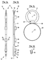
- Fig. 1a and 1b show a hose assembly 10 with a flexible disposable tube 11, wherein the Fig. 1b one opposite the Fig. 1a represents 90 ° rotated about a longitudinal axis 12 view.
- the tubing assembly 10 has a distal end 14 and a proximal end 16.
- a fixation sleeve 26 is attached to the disposable tube 11.
- the fixation cuff 26 is further proximal than an opening 18 and an exit opening 20 so that the distal end of an endoscope (not shown) to be inserted into the fixation cuff 26 is in visual contact with the openings laterally attached to the disposable tube 11 with respect to the longitudinal axis 12 18, 20 stands.
- the opening 18 and the outlet opening 20 are connected to a working channel 22 and an optional flushing channel 24 (shown in FIG Fig. 1c ) of the disposable tube 11 in conjunction.
- the outlet opening 20 of the flushing channel 24 is arranged at a small distance distally offset to the fixing collar 26.
- rinsing liquid can be sprayed onto the optics of the endoscope to clean them and to remove, for example, disturbing secretions.
- air may also be passed through the flushing channel 24 to not only blow open the optics of the endoscope, but also to inflate the cavity to be examined by air insufflation so that a wall of, for example, the stomach or esophagus can be better observed.
- the opening 18 of the working channel 22 is offset relative to the fixing sleeve 26 further distally than the outlet opening 20. Since it is also arranged with respect to the longitudinal axis 12 of the disposable tube 11 on the fixing sleeve 26 side facing, it is for example possible to suck up secretions or other substances in the area directly in front of the endoscope.
- guide loops 28 are attached to the disposable tube 11 of the tube assembly 10. They are arranged at regular intervals, this being merely a special embodiment.
- Fig. 1c illustrates the structure of the hose assembly based on a cross section along the section line AA of Fig. 1a , In the upper part of the Fig. 1c the cross section of the disposable tube 11 can be seen.
- the disposable tube 11 comprises the working channel 22 and the optional flushing channel 24.
- the working channel 22 has a substantially larger cross-sectional area than the flushing channel 24. Depending on requirements, a different distribution may be selected.
- the cross-section of the working channel 22 can be simplified by a combination of a circular arc section with a part of a trapezoid with rounded corners describe.
- the deviation from a circular cross-section of the working channel 22 for a given outer diameter of the disposable tube 11 allows a more efficient passage of liquid or pieces of tissue.
- a work tool with a circular cross-section in such a shaped working channel 22 can be moved more easily, since the contact surface to the inner walls of the working channel 22 is smaller than in the case of a circular cross-section and thus less friction occurs.
- the side walls of the disposable tube which laterally delimit the working channel 22 are designed to be relatively thick, for example with respect to the wall section of the disposable tube 11 opposite the flushing channel 24. This results in a bending of the disposable tube 11 by means of the endoscope (see. Fig. 5c ) prevents collapse of the working channel 22.
- the flushing channel 24 is optimized in its cross-sectional shape and size such that a sufficient supply of flushing liquid for cleaning the optics of the endoscope can always be supplied with optimal cross-sectional area utilization of the disposable tube 11.
- the flushing channel 24 is located between the working channel 22 and the guide loops 28, d. H. on a line connecting the longitudinal axis 12 of the disposable tube 11 and a longitudinal axis 12 'extending parallel thereto, which extends along the longitudinal axes of the guide loops 28 and the fixing collar 26.
- the lower part of the picture in Fig. 1c is taken from the cross section of one of the guide loops 28.
- This has a circular cross section, which serves to receive the endoscope.
- the endoscope can move in particular in the longitudinal direction.
- the guide loops 28 thus serve to hold the disposable tube 11 of the tube assembly 10 in the lateral direction in close spatial proximity to the endoscope, but not firmly connect them together.
- the guide loop 28 is glued to the disposable tube, as indicated by the adhesive connection 30.
- the type of connection can be chosen freely, for example, a welded connection or a shrink connection is alternatively possible.
- a one-piece design of the disposable tube 11 and the guide loops 28 is conceivable. The same applies to the fixing collar 26.
- Fig. 1d shows a cross section through the Fixiermanschette 26 along the section line BB of Fig. 1b , It can be clearly seen that the inner diameter of the fixation cuff 28 is distally smaller than it is proximal.
- the fixing collar 26 preferably consists of an elastic material, so that the inner radius-reduced area of the fixing collar 26 is widened by the insertion of the distal end of the endoscope. This creates a frictional connection between the Fixiermanschette 26 - which is indeed firmly connected to the disposable tube 12 - and the endoscope. A reliable fixation is thus ensured.
- the working channel 22 and the flushing channel 24 are connected to separate connecting tubes 32, which serve to supply / discharge of liquids and / or tissue parts.
- the flushing channel 24 may in the embodiment according to Fig. 1a to 1d also omitted, especially for applications of the hose assembly 10 in the ear, nose and throat (ENT) area.
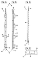
- FIG Fig. 2a and 2b A somewhat modified embodiment of the hose assembly 10 is shown in FIG Fig. 2a and 2b shown (not an embodiment of the invention).
- the two embodiments are similar, particularly with respect to the cross-sectional shape of the tube assembly 10.
- the opening 18 of the working channel 22 is not attached laterally, but is axially aligned with respect to the longitudinal axis 12.
- the distal end of the disposable tube 11 cut perpendicular to the longitudinal axis 12.
- this embodiment in the present form can also be used, for example, for extracting substances.
- this embodiment is particularly suitable for guiding work tools through the working channel 22. This is especially true when the flushing channel 24 with the outlet opening 20 is omitted.
- the working channel 22 but also similar to in Fig. 1a and b shown embodiment, when an inner tube 34 is used, which is guided through the working channel 22.
- Such inner tube 34 is in Fig. 2c shown. At its proximal end 16 it is connected to a connecting tube 32.
- the distal end 16 of the inner tube 34 is similar to the tip of FIG Fig. 1a and 1b illustrated embodiment of the hose assembly 10.
- the inner tube 34 has a laterally disposed slot which represents the opening 18.
- the opening 18 of the inner tube 34 is shown in more detail in FIG Fig. 2d illustrated, wherein the dashed line symbolizes the wall thickness of the inner tube 34.
- the opening 18 is dimensioned such that it has the greatest possible width in a direction perpendicular to the longitudinal axis 12, so that even relatively large pieces of tissue or secretion lumps can be sucked off.
- the advantage of this embodiment in combination with the use of the inner tube 34 is that the opening 18 can be positioned almost arbitrarily relative to the fixation cuff 26 by turning and pushing the inner tube 34, and thus relative to the endoscope. For example, a larger area of the examination area can be achieved with the opening 18 with unchanged position of the disposable tube 11 and the endoscope. The treating physician is given such a flexible working device in the hand.
- FIG Fig. 3a Another embodiment of the hose assembly 10 is shown in FIG Fig. 3a shown. It shows a disposable tube 11 which is provided with guide loops 28 and a fixing collar 26.
- the proximal guide loop 28 has a significantly greater longitudinal extent than the distal guide loop 28 of the embodiments discussed above.
- the distal end of the disposable tube 11 is flush with the distal end of the Fixiermanschette 26.
- a closure cap 36 eg Fig. 3b ).
- the end cap 36 is attached to the disposable tube 11 or otherwise connected to this.
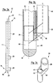
- FIG Fig. 3b A sectional view through the distal end 14 of the tube assembly 10 is shown in FIG Fig. 3b shown.
- the disposable tube 11 has a working channel 22 and a flushing channel 24.
- a connecting sleeve 38 is inserted, in turn, the end cap 36 is attached.
- the connecting sleeve 38 and the end cap 36 may also be made in one piece.
- the end cap 36 has a groove 40. If the end cap 36 is connected to the disposable tube 11, this groove 40 forms the outlet opening 20 of the flushing channel 24. Furthermore, the end cap 36 has a channel 42 which communicates with the working channel 22 and which comprises a laterally arranged opening 18. Functionally and with respect to the arrangement of the openings 18, 20 of the channels 22, 24 therefore resembles in the Fig. 3b illustrated embodiment of the hose assembly 10 of in Fig. 1a and 1b illustrated embodiment.
- An integral part of the end cap 36 is also the fixing collar 26, which rotatably and axially fixedly connects an endoscope 44 with the end cap 36 and thus the disposable tube 11.
- the detailed illustration of the distal end 14 of the tube assembly 10 illustrates the spatial proximity of the openings 18, 20 to the distal end of the endoscope 44.
- Effluent flushing liquid can be efficiently injected onto the endoscope optic through the outlet opening 20 in order to clean it. In the visual field of the optics of the endoscope, however, secretion or the like can be simply sucked through the opening 18.
- the end cap 36 is an easy-to-manufacture component and may, for example, have various variations in the shapes and orientations of the apertures 18, 20. Also, the openings 18, 20 may be arranged on different sides.
- the inner tube 34 may also be provided with such an end cap, both in the embodiment of the inner tube 34 with only one working channel 22 and in the embodiment of the inner tube 34 with a working channel 22 and a flushing channel 24th
- FIG. 3c A perspective view of such an end cap is in Fig. 3c shown.
- the end cap 36 of Fig. 3c has two connecting webs 46 which connects the fixing collar 26 with the part of the end cap 36 containing the openings 18, 20.
- the location of the connecting webs 46 relative to the other elements of the end cap 36 is in Fig. 3b indicated by obliquely to the longitudinal axes 12, 12 'extending dashed lines.
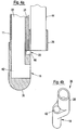
- FIG. 4a A slightly different embodiment of a end cap 36 illustrates Fig. 4a ,
- the end cap 36 is attached to the disposable tube 11, so that can be dispensed with a connection sleeve 38.
- the rest of the structure of the end cap 36 is similar to that of Fig. 3b shown embodiment.
- Fig. 4b shows a perspective view of the in Fig. 4a
- the embodiment of the end cap 36 The groove 40 forming the outlet opening 20 of the flushing channel 24 is again arranged at the distal end of the fixing collar 26, so that the groove 40 in the perspective shown in FIG Fig. 4b not visible.
- FIG Fig. 5a An advantageous modification of the hose assembly 10 is shown in FIG Fig. 5a shown (not an embodiment of the invention).
- the essential features of the distal end 14 of the hose assembly 10, such as the opening 18, the opening 20 of the optional flushing channel, the fixing collar 26 and the guide loop 28, have already been described in detail above.
- the illustrated embodiment additionally has a coil spring 48 embedded in the disposable tube 11, such as Fig. 5b can be seen.
- Fig. 5b shows a section perpendicular to a section line CC of Fig. 5a ,
- the coil spring 48 extends over a portion of the distal portion of the tubing assembly 10 that is proximally offset relative to the exit port 20 of the flushing channel 24. It is bendable, that is elastically bendable perpendicular to the longitudinal axis 12, wherein its cross-sectional shape changes only insignificantly at a bend. It is thereby achieved that at a curvature of the hose assembly 10, the channels 22, 24 are not compressed, whereby, for example, the supply / supply of liquid and / or tissue would be prevented.
- Such a reinforcing element in the form of a coil spring 48 - wherein other reinforcing elements can be used - is particularly advantageous in situations when the endoscope is brought into inversion.
- the endoscope 44 is strongly curved, so that the endoscope optics looks "backwards" to the proximal (see Fig. 5c ).
- the coil spring 48 Without the coil spring 48, the tube cross section of the disposable tube 11 would be squeezed together.
- the supply, for example, of rinsing liquid would be interrupted.
- the same supporting effect can be achieved for example by a the disposable tube 11 sections surrounding coil spring.
- the guide loops 28 should allow a relative movement between the endoscope 44 and the disposable tube 11. If the connection between the guide loops 28 and the endoscope 44 were fixed and no longitudinally displaceable movement were permitted, then due to the different radii of curvature of the disposable tube 11 and the endoscope 44, strong stretching loads in the longitudinal direction would occur in the disposable tube 11 or in the endoscope 44, on the one hand the On the other hand, could also cause collapse of the cross sections of the channels 22, 24, or could cause damage to the Bowden cables of the endoscope 44.
- Fig. 6a shows the distal end 14 of one embodiment of the tube assembly 10 (not an embodiment of the invention).
- the working channel 22 and the optional flushing channel 24 of the disposable tube 11 are not shown because their arrangement is of secondary importance to the aspect to be described below.
- the arrows D, E indicate that both the flushing channel 24 and the working channel 22 through the lateral openings 20 and 18 of the disposable tube 11 are in communication with a region in front of the endoscope 44.
- the distal end 14 of the tube assembly 10 is closed by a end piece 36a.
- the two in the longitudinal direction of the disposable tube 11 mutually offset openings 18, 20 are not closed by the end piece 36a.
- Fig. 6b shows another embodiment of the hose assembly 10 (not an embodiment of the invention), which, however, relies on the same disposable tube 11, as in Fig. 6a shown embodiment.
- the cap or peg-like end piece 36a of the Fig. 6a was here replaced by a hollow cylindrical end piece 36b, which leaves the axial opening at the distal end 14 of the disposable tube 11 open.
- the end piece 36b closes the lateral working channel opening 18, so that the working channel 22 is now in communication with a region in front of the distal end 14 of the hose assembly 10.
- the optional lateral outlet opening 20 of the flushing channel 24 is still open.
- the end pieces 36a, 36b may also be designed so that they are attached to the disposable tube 11 - not plugged in as in Fig. 6a and 6b - or otherwise attached to this.
- Corresponding end pieces 36a, 36b can also be found in embodiments of the hose assembly 10 with inner tube 34 use.
- the hose assembly 10 of the present invention may include more than one purge passage 24, as in FIG Fig. 7a is shown.
- This embodiment has two flushing channels 24, 24 ', which are not directly between the working channel 22 and the fixing device - here a Fixiermanschette 26' with a sectionally different from a circle cross-section - are arranged.
- the flushing channels 24, 24 ' are laterally offset relative to a connecting line FF between the longitudinal axis 12 of the disposable tube 11 and the longitudinal axis 12' of the fixing collar 26 '. They are arranged symmetrically on both sides of the connecting line FF.
- the disposable tube 11 in such a configuration for a given diameter of the working channel 22 (lumen) have a smaller wall thickness.
- the outlet openings 20 of the flushing channels 24, 24 'need not be aligned in the longitudinal direction of the hose assembly 10 or lie in a common cross-sectional plane, but may be arranged arbitrarily to different areas - possibly also independently - to be able to flush.
- FIG Fig. 7b An example of an embodiment with a single offset flushing channel 24 is shown in FIG Fig. 7b shown.
- the area of the flushing channel 24 'of the Fig. 7a was slammed into the working channel. This area can be used, for example, to guide another thin tube or work equipment / instruments.
- Fig. 8a to 8c show various embodiments of a fastener through which the guide loops 28 and / or the Fixiermanschette 26, 26 'can be provided.
- the fastener is formed by a single-piece band 50 which is easy to manufacture and which surrounds both the disposable tube 11 and the endoscope 44.
- the band 50 may be releasably or firmly connected to the disposable tube 11.
- band is not to suggest that the band 50 must be flexible, for example, as a type of rubber band. It may also be, for example, a relatively rigid plastic component.
- the band 50 acts as a fixing collar 26, 26 ', then it fixes the endoscope 44 in a rotationally fixed and in the axial direction. If it serves only to guide the endoscope 44, then it is designed such that the endoscope 44 can move relative to the disposable tube 11.
- Fig. 8a shows a simple variant of the band 50. It forms a single loop 54, in which the disposable tube 11 and the endoscope 44 are arranged.
- the loop 54 has substantially the shape of an "O".
- the band 50 of the Fig. 8b a waist 52 through which two loops 54, 54 'are defined so that the band 50 forms a shape similar to an imperfect "8".
- that is Constriction in the central region of the band 50 is not complete, whereby a connection between the two loops 54, 54 'is made.
- the loop 54 of the disposable tube 11 is arranged, while the loop 54 'receives the endoscope 44.
- the advantage of the waisted band 50 is that mutual twisting of the disposable tube 11 and the endoscope 44 is prevented. Such twisting causes problems, in particular with an inversion of the endoscope 44.
- Fig. 8c shows a band 50 with a sidecut 52, the loops 54, 54 'are separated by a web 53, whereby the shape of an "8" is formed.
- the band 50 may also have only the web 53 so that the outer contour of the band 50 corresponds to an "O", as in the case of FIG Fig. 8a shown embodiment of the band 50th
Landscapes
- Health & Medical Sciences (AREA)
- Life Sciences & Earth Sciences (AREA)
- Surgery (AREA)
- Engineering & Computer Science (AREA)
- Heart & Thoracic Surgery (AREA)
- Biophysics (AREA)
- Veterinary Medicine (AREA)
- Public Health (AREA)
- General Health & Medical Sciences (AREA)
- Animal Behavior & Ethology (AREA)
- Biomedical Technology (AREA)
- Medical Informatics (AREA)
- Physics & Mathematics (AREA)
- Molecular Biology (AREA)
- Radiology & Medical Imaging (AREA)
- Pathology (AREA)
- Optics & Photonics (AREA)
- Nuclear Medicine, Radiotherapy & Molecular Imaging (AREA)
- General Engineering & Computer Science (AREA)
- Otolaryngology (AREA)
- Mechanical Engineering (AREA)
- Pulmonology (AREA)
- Physiology (AREA)
- Hematology (AREA)
- Anesthesiology (AREA)
- Endoscopes (AREA)
Claims (15)
- Agencement à tuyau souple pour un endoscope, comprenant au moins un tuyau à jeter (11) qui entoure un canal de travail (22) et comprenant un moyen de fixation d'endoscope pour fixer le tuyau à jeter (11) sur un endoscope (44),
dans lequel le moyen de fixation d'endoscope comprend un dispositif de fixation (26, 26') au moyen duquel le tuyau à jeter (11) est susceptible d'être fixé solidaire en rotation et fixe en direction axiale à l'extrémité distale de l'endoscope (44), et
dans lequel le moyen de fixation d'endoscope comprend en outre au moins un dispositif de guidage (28) au moyen duquel le tuyau à jeter (11) est susceptible d'être fixé de manière déplaçable à une portion respective de l'endoscope (44) à distance de l'extrémité distale de l'endoscope (44),
caractérisé en ce que
l'agencement à tuyau souple (10) inclut un capuchon de terminaison (36) qui est relié avec l'extrémité distale du tuyau à jeter (11), et le capuchon de terminaison (36) est relié fermement avec le dispositif de fixation (26, 26'). - Agencement à tuyau souple selon la revendication 1,
caractérisé en ce que le capuchon de terminaison (36) est réalisé d'une seule pièce avec le dispositif de fixation (26, 26'). - Agencement à tuyau souple selon la revendication 1 ou 2,
caractérisé en ce que l'ouverture (18) du canal de travail (22) et/ou l'ouverture de sortie (20) d'un canal de rinçage (24) de l'agencement à tuyau souple sont réalisées sur le capuchon de terminaison (36). - Agencement à tuyau souple selon l'une au moins des revendications précédentes,
caractérisé en ce que le dispositif de guidage (28) inclut plusieurs boucles réalisées essentiellement en forme de cylindre creux, qui sont agencées à distance les unes des autres le long de la longueur du tuyau à jeter (11). - Agencement à tuyau souple selon l'une au moins des revendications précédentes,
caractérisé en ce que le dispositif de guidage (28) est réalisé sous forme d'un élément de fixation respectif (50) d'une seule pièce, qui entoure le tuyau à jeter (11) et l'endoscope (44) et qui comporte un récepteur pour tuyau à jeter (54) et un récepteur pour endoscope (54), lesquels sont définis par un rétrécissement (52) et/ou par une barrette (53). - Agencement à tuyau souple selon l'une au moins des revendications précédentes,
caractérisé en ce que le dispositif de guidage (28) et/ou le dispositif de fixation (26, 26') est relié fermement avec le tuyau à jeter (11) ou est réalisé d'une seule pièce avec le tuyau à jeter (11). - Agencement à tuyau souple selon l'une au moins des revendications précédentes,
caractérisé en ce que
le dispositif de fixation (26, 26') est en matériau élastique et comporte une ouverture de réception axiale dont le diamètre intérieur, le long d'au moins une partie de l'extension longitudinale du dispositif de fixation, est dimensionné pour assurer une liaison à coopération de friction avec l'endoscope (44),
et/ou en ce que le dispositif de fixation (26, 26') est réalisé comme une manchette ouverte des deux côtés en direction axiale. - Agencement à tuyau souple selon l'une au moins des revendications précédentes,
caractérisé en ce que le tuyau à jeter (11) entoure additionnellement au moins un canal de rinçage (24), ledit agencement à tuyau souple (10) comprenant une ouverture de sortie (20) du canal de rinçage (24), laquelle est agencée décalée en direction distale par rapport au dispositif de fixation (26, 26') pour l'extrémité distale de l'endoscope (44), et ledit agencement à tuyau souple (10) comprenant une ouverture (18) du canal de travail (22), laquelle est également agencée décalée en direction distale par rapport au dispositif de fixation (26, 26') pour l'extrémité distale de l'endoscope (44). - Agencement à tuyau souple selon la revendication 8,
caractérisé en ce que l'ouverture de sortie (20) du canal de rinçage (24) est réalisée sous forme de fente. - Agencement à tuyau souple selon la revendication 8 ou 9,
caractérisé en ce que le canal de rinçage (24) est agencé, par référence à une section transversale de l'agencement à tuyau souple (10), entre le canal de travail (22) et le moyen de fixation pour endoscope. - Agencement à tuyau souple selon l'une des revendications 8 à 10,
caractérisé en ce que
l'ouverture de sortie (10) du canal de rinçage (24) est agencée en situation distale au voisinage du dispositif de fixation (26, 26') pour l'extrémité distale de l'endoscope (44),
et/ou en ce que l'ouverture (18) du canal de travail (22) est agencée en décalage en direction distale par rapport à l'ouverture de sortie (20) du canal de rinçage (24). - Agencement à tuyau souple selon l'une au moins des revendications précédentes,
caractérisé en ce que l'ouverture (18) du canal de travail (22) et/ou l'ouverture de sortie (20) d'un canal de rinçage (24) de l'agencement à tuyau souple sont agencées latéralement. - Agencement à tuyau souple selon l'une au moins des revendications précédentes,
caractérisé en ce que le canal de travail (22) et/ou un canal de rinçage (24) de l'agencement à tuyau souple présentent une section transversale qui diffère d'une forme circulaire. - Agencement à tuyau souple selon l'une au moins des revendications précédentes,
caractérisé en ce que le tuyau à jeter (11) comprend au moins un élément de renforcement (48) capable d'être cintré, qui est agencé en particulier dans une région distale de l'agencement à tuyau souple (10), qui est agencé en décalage en direction proximale par rapport à l'ouverture de sortie (20) d'un canal de rinçage (22) de l'agencement à tuyau souple. - Agencement à tuyau souple selon la revendication 14,
caractérisé en ce que l'élément de renforcement (48) inclut un ressort spiralé fixé sur le tuyau à jeter (11) ou noyé dans le tuyau à jeter (11).
Applications Claiming Priority (2)
| Application Number | Priority Date | Filing Date | Title |
|---|---|---|---|
| DE102007008099.0A DE102007008099B4 (de) | 2007-02-19 | 2007-02-19 | Schlauchanordnung für ein Endoskop |
| PCT/EP2008/001238 WO2008101653A2 (fr) | 2007-02-19 | 2008-02-18 | Système tubulaire pour endoscope |
Publications (2)
| Publication Number | Publication Date |
|---|---|
| EP2124706A2 EP2124706A2 (fr) | 2009-12-02 |
| EP2124706B1 true EP2124706B1 (fr) | 2016-07-27 |
Family
ID=39628129
Family Applications (1)
| Application Number | Title | Priority Date | Filing Date |
|---|---|---|---|
| EP08715835.8A Not-in-force EP2124706B1 (fr) | 2007-02-19 | 2008-02-18 | Système tubulaire pour endoscope |
Country Status (6)
| Country | Link |
|---|---|
| US (2) | US8469880B2 (fr) |
| EP (1) | EP2124706B1 (fr) |
| DE (1) | DE102007008099B4 (fr) |
| DK (1) | DK2124706T3 (fr) |
| ES (1) | ES2600428T3 (fr) |
| WO (1) | WO2008101653A2 (fr) |
Families Citing this family (19)
| Publication number | Priority date | Publication date | Assignee | Title |
|---|---|---|---|---|
| GB0716672D0 (en) * | 2007-08-28 | 2007-10-03 | Aircraft Medical Ltd | Laryngoscope |
| GB2452406B (en) | 2007-08-28 | 2010-03-17 | Aircraft Medical Ltd | Laryngoscope insertion section |
| DE102009014178A1 (de) | 2009-03-20 | 2010-09-23 | Ingo F. Prof. Dr. Herrmann | Endoskop-System |
| USD645561S1 (en) * | 2009-03-23 | 2011-09-20 | Ingoscope Systems Gmbh | Distal cap for a working channel tube |
| DE102010049568A1 (de) | 2009-10-27 | 2011-04-28 | Ingoscope Systems Gmbh | Schlauchanordnung für ein Endoskop |
| WO2012021440A1 (fr) * | 2010-08-10 | 2012-02-16 | Cook Medical Technologies Llc | Système endoscopique pour résection de tissu |
| JP5637781B2 (ja) * | 2010-08-30 | 2014-12-10 | 富士フイルム株式会社 | ドレナージチューブ及びドレナージチューブ付内視鏡 |
| DE102010047434A1 (de) | 2010-10-04 | 2012-04-05 | Ingoscope Systems Gmbh | Einwegschlauch für ein Endoskop |
| IT1403013B1 (it) | 2010-12-10 | 2013-09-27 | Matteja | Dispositivo di fissaggio per collegare l'estremita' di un endoscopio ad un tubo |
| EP2671502A1 (fr) | 2012-06-08 | 2013-12-11 | Infobroking Limited | Dispositif de fixation permettant de coupler l'extrémité d'un endoscope à un tuyau |
| DE102012219342A1 (de) * | 2012-10-23 | 2014-04-24 | Ingoscope Systems Gmbh | Endoskopie- und Biopsie-Einwegsystem |
| DE102013212822A1 (de) | 2013-07-01 | 2015-01-08 | Ingoscope Systems Gmbh | Befestigungsvorrichtung |
| CN105326468A (zh) * | 2014-07-22 | 2016-02-17 | 芯发威达电子(上海)有限公司 | 具防水结构的咽喉镜及其防水结构 |
| US11304594B2 (en) * | 2016-01-29 | 2022-04-19 | Meditrina, Inc. | Articulating medical device |
| DE102017107546A1 (de) * | 2017-04-07 | 2018-10-11 | Ovesco Endoscopy Ag | Endoskop mit zusätzlichem externem Arbeitskanal |
| US11076745B2 (en) * | 2017-05-26 | 2021-08-03 | Covidien Lp | Bronchoscopy coupling devices |
| DE102017010987A1 (de) * | 2017-11-28 | 2019-05-29 | Karl Storz Se & Co. Kg | Laryngoskopspatel und Verfahren zum Herstellen eines Laryngoskopspatels |
| US20210228062A1 (en) * | 2020-01-28 | 2021-07-29 | Gyrus Acmi, Inc. D/B/A Olympus Surgical Technologies America | Endoscope and endoscope attachments |
| EP3871585B1 (fr) | 2020-02-28 | 2025-04-09 | Gyrus ACMI, Inc. d/b/a Olympus Surgical Technologies America | Dispositif de fixation électrochirurgical |
Citations (1)
| Publication number | Priority date | Publication date | Assignee | Title |
|---|---|---|---|---|
| WO2001087144A1 (fr) * | 2000-05-15 | 2001-11-22 | C.R. Bard, Inc. | Mecanisme de fixation d'un accessoire endoscopique |
Family Cites Families (27)
| Publication number | Priority date | Publication date | Assignee | Title |
|---|---|---|---|---|
| JPS61259637A (ja) * | 1985-05-15 | 1986-11-17 | オリンパス光学工業株式会社 | 内視鏡装置 |
| US5199417A (en) * | 1990-12-21 | 1993-04-06 | Circon Corporation | Endoscope having a deflectable distal section and a semi-rigid proximal section |
| US5863286A (en) * | 1993-01-27 | 1999-01-26 | Olympus Optical Company, Ltd. | Endoscope system including endoscope and disposable protection cover |
| US5483951A (en) | 1994-02-25 | 1996-01-16 | Vision-Sciences, Inc. | Working channels for a disposable sheath for an endoscope |
| US6579582B1 (en) | 1997-10-10 | 2003-06-17 | Vision Sciences Inc. | Apparatus and method for forming complex-shaped components in a heated polymeric film |
| JP4121615B2 (ja) * | 1997-10-31 | 2008-07-23 | オリンパス株式会社 | 内視鏡 |
| US6530881B1 (en) | 1999-01-21 | 2003-03-11 | Vision Sciences, Inc. | Sheath apparatus for endoscopes and methods for forming same |
| US6350231B1 (en) | 1999-01-21 | 2002-02-26 | Vision Sciences, Inc. | Apparatus and method for forming thin-walled elastic components from an elastomeric material |
| US6358200B1 (en) * | 1999-09-01 | 2002-03-19 | Circon Corporation | Continuous flow resectoscope with single tube sheath assembly and rotatable connection |
| US6537205B1 (en) * | 1999-10-14 | 2003-03-25 | Scimed Life Systems, Inc. | Endoscopic instrument system having reduced backlash control wire action |
| US6454702B1 (en) * | 1999-10-14 | 2002-09-24 | Scimed Life Systems, Inc. | Endoscope and endoscopic instrument system having reduced backlash when moving the endoscopic instrument within a working channel of the endoscope |
| US6786884B1 (en) * | 1999-10-29 | 2004-09-07 | Bard Access Systems, Inc. | Bolus tip design for a multi-lumen catheter |
| DE10000091A1 (de) | 2000-01-04 | 2001-07-05 | Ingo F Herrmann | Endoskop |
| EP1309266B1 (fr) | 2000-08-10 | 2013-07-17 | Vision Sciences, Inc. | Procede de production de composants de forme complexe dans un film polymere chauffe et appareil correspondant |
| US6431218B1 (en) * | 2000-09-28 | 2002-08-13 | Vital Signs, Inc. | Multi-lumen hose with at least one substantially planar inner partition and methods of manufacturing the same |
| US8313496B2 (en) * | 2001-02-02 | 2012-11-20 | Lsi Solutions, Inc. | System for endoscopic suturing |
| US6824509B2 (en) | 2001-07-23 | 2004-11-30 | Olympus Corporation | Endoscope |
| DE10139153A1 (de) * | 2001-08-09 | 2003-02-27 | Ingo F Herrmann | Einweg-Endoskopmantel |
| US6740030B2 (en) | 2002-01-04 | 2004-05-25 | Vision Sciences, Inc. | Endoscope assemblies having working channels with reduced bending and stretching resistance |
| US7060024B2 (en) | 2002-03-15 | 2006-06-13 | Ethicon Endo-Surgery, Inc. | Apparatus for guiding an instrument used with an endoscope |
| JP2007503277A (ja) * | 2003-04-22 | 2007-02-22 | カンポス,ジヨージ・エイ | 窩洞の見にくい部分を観察するためのシステム、装置、及び方法 |
| US7431694B2 (en) | 2003-05-16 | 2008-10-07 | Ethicon Endo-Surgery, Inc. | Method of guiding medical devices |
| WO2005016181A2 (fr) | 2003-08-04 | 2005-02-24 | Vision-Sciences, Inc. | Gaine a canal pour endoscope |
| EP1740084A2 (fr) * | 2004-04-15 | 2007-01-10 | Wilson-Cook Medical Inc. | Dispositifs d'acces chirurgical endoscopiques et procede d'articulation d'un canal accessoire externe |
| JP4648785B2 (ja) * | 2005-07-20 | 2011-03-09 | Hoya株式会社 | 内視鏡用体内留置バルーンカテーテル |
| US7918783B2 (en) * | 2006-03-22 | 2011-04-05 | Boston Scientific Scimed, Inc. | Endoscope working channel with multiple functionality |
| US7794393B2 (en) * | 2006-04-13 | 2010-09-14 | Larsen Dane M | Resectoscopic device and method |
-
2007
- 2007-02-19 DE DE102007008099.0A patent/DE102007008099B4/de not_active Expired - Fee Related
-
2008
- 2008-02-18 WO PCT/EP2008/001238 patent/WO2008101653A2/fr not_active Ceased
- 2008-02-18 DK DK08715835.8T patent/DK2124706T3/en active
- 2008-02-18 ES ES08715835.8T patent/ES2600428T3/es active Active
- 2008-02-18 US US12/526,967 patent/US8469880B2/en not_active Expired - Fee Related
- 2008-02-18 EP EP08715835.8A patent/EP2124706B1/fr not_active Not-in-force
-
2013
- 2013-06-05 US US13/910,365 patent/US9931019B2/en active Active
Patent Citations (1)
| Publication number | Priority date | Publication date | Assignee | Title |
|---|---|---|---|---|
| WO2001087144A1 (fr) * | 2000-05-15 | 2001-11-22 | C.R. Bard, Inc. | Mecanisme de fixation d'un accessoire endoscopique |
Also Published As
| Publication number | Publication date |
|---|---|
| US9931019B2 (en) | 2018-04-03 |
| DE102007008099B4 (de) | 2021-05-20 |
| DE102007008099A1 (de) | 2008-08-21 |
| EP2124706A2 (fr) | 2009-12-02 |
| US20130267780A1 (en) | 2013-10-10 |
| ES2600428T3 (es) | 2017-02-09 |
| US8469880B2 (en) | 2013-06-25 |
| DK2124706T3 (en) | 2016-11-21 |
| US20100210909A1 (en) | 2010-08-19 |
| WO2008101653A3 (fr) | 2009-02-26 |
| WO2008101653A2 (fr) | 2008-08-28 |
Similar Documents
| Publication | Publication Date | Title |
|---|---|---|
| EP2124706B1 (fr) | Système tubulaire pour endoscope | |
| EP1284120B1 (fr) | Gaine à usage unique pour un endoscope | |
| DE2800362C3 (de) | Endoskop mit steuerbar beweglicher Führungsröhre für ein Instrument | |
| DE4305376C1 (de) | Schaft für medizinische Instrumente | |
| WO2019229206A1 (fr) | Gaine d'introduction pouvant être commandée | |
| EP1713376A1 (fr) | Endoscope comprenant une sonde flexible | |
| EP3876819A1 (fr) | Instrument endoscopique | |
| DE19855968C1 (de) | Medizinisches Rohrschaftinstrument | |
| DE9318282U1 (de) | Endoskopisches Instrument | |
| DE4320962A1 (de) | Katheter aus einem biegsamen Kunststoffschlauch | |
| EP0489937A1 (fr) | Instrument médical avec tête orientable | |
| DE602004012173T2 (de) | Drahtkorbzange | |
| EP1754438B1 (fr) | Endoscope, notamment duodendoscope pour mère-enfant-cholangioscopy | |
| EP2401020B1 (fr) | Cathéter | |
| DE202009017988U1 (de) | Chirurgisches Instrument | |
| EP2903494B1 (fr) | Système d'endoscopie et de biopsie à usage unique | |
| EP2361040B1 (fr) | Instrument pour chirurgie laparoscopique | |
| EP0530595A1 (fr) | Manchon de trocart | |
| DE102016001271A1 (de) | Transporteur eines Resektoskopes | |
| DE102017113069A1 (de) | Transporteur eines Resektoskopes und Elektrodeninstrument | |
| EP3155973B1 (fr) | Pince à biopsie | |
| EP3173038B1 (fr) | Instrument à queue | |
| WO2018233940A1 (fr) | Poignée de commande manuelle pour instrument d'endoscopie | |
| DE102004056136A1 (de) | Chirurgisches Instrument zur Biopsatentnahme | |
| DE102016010548B4 (de) | Transporteur |
Legal Events
| Date | Code | Title | Description |
|---|---|---|---|
| PUAI | Public reference made under article 153(3) epc to a published international application that has entered the european phase |
Free format text: ORIGINAL CODE: 0009012 |
|
| 17P | Request for examination filed |
Effective date: 20090918 |
|
| AK | Designated contracting states |
Kind code of ref document: A2 Designated state(s): AT BE BG CH CY CZ DE DK EE ES FI FR GB GR HR HU IE IS IT LI LT LU LV MC MT NL NO PL PT RO SE SI SK TR |
|
| RAP1 | Party data changed (applicant data changed or rights of an application transferred) |
Owner name: INGOSCOPE SYSTEMS GMBH |
|
| DAX | Request for extension of the european patent (deleted) | ||
| 17Q | First examination report despatched |
Effective date: 20141127 |
|
| REG | Reference to a national code |
Ref country code: DE Ref legal event code: R079 Ref document number: 502008014435 Country of ref document: DE Free format text: PREVIOUS MAIN CLASS: A61B0001018000 Ipc: A61B0001000000 |
|
| GRAP | Despatch of communication of intention to grant a patent |
Free format text: ORIGINAL CODE: EPIDOSNIGR1 |
|
| RIC1 | Information provided on ipc code assigned before grant |
Ipc: A61B 1/227 20060101ALI20160119BHEP Ipc: A61B 1/018 20060101ALI20160119BHEP Ipc: A61B 1/233 20060101ALI20160119BHEP Ipc: A61B 1/267 20060101ALI20160119BHEP Ipc: A61B 1/12 20060101ALI20160119BHEP Ipc: A61B 1/00 20060101AFI20160119BHEP |
|
| INTG | Intention to grant announced |
Effective date: 20160208 |
|
| GRAS | Grant fee paid |
Free format text: ORIGINAL CODE: EPIDOSNIGR3 |
|
| GRAA | (expected) grant |
Free format text: ORIGINAL CODE: 0009210 |
|
| AK | Designated contracting states |
Kind code of ref document: B1 Designated state(s): AT BE BG CH CY CZ DE DK EE ES FI FR GB GR HR HU IE IS IT LI LT LU LV MC MT NL NO PL PT RO SE SI SK TR |
|
| REG | Reference to a national code |
Ref country code: GB Ref legal event code: FG4D Free format text: NOT ENGLISH |
|
| REG | Reference to a national code |
Ref country code: CH Ref legal event code: EP |
|
| REG | Reference to a national code |
Ref country code: AT Ref legal event code: REF Ref document number: 815096 Country of ref document: AT Kind code of ref document: T Effective date: 20160815 |
|
| REG | Reference to a national code |
Ref country code: IE Ref legal event code: FG4D Free format text: LANGUAGE OF EP DOCUMENT: GERMAN |
|
| REG | Reference to a national code |
Ref country code: DE Ref legal event code: R096 Ref document number: 502008014435 Country of ref document: DE |
|
| REG | Reference to a national code |
Ref country code: CH Ref legal event code: NV Representative=s name: INTELLECTUAL PROPERTY SERVICES GMBH, CH |
|
| REG | Reference to a national code |
Ref country code: NL Ref legal event code: FP |
|
| REG | Reference to a national code |
Ref country code: SE Ref legal event code: TRGR |
|
| REG | Reference to a national code |
Ref country code: DK Ref legal event code: T3 Effective date: 20161117 |
|
| REG | Reference to a national code |
Ref country code: LT Ref legal event code: MG4D |
|
| PG25 | Lapsed in a contracting state [announced via postgrant information from national office to epo] |
Ref country code: LT Free format text: LAPSE BECAUSE OF FAILURE TO SUBMIT A TRANSLATION OF THE DESCRIPTION OR TO PAY THE FEE WITHIN THE PRESCRIBED TIME-LIMIT Effective date: 20160727 Ref country code: NO Free format text: LAPSE BECAUSE OF FAILURE TO SUBMIT A TRANSLATION OF THE DESCRIPTION OR TO PAY THE FEE WITHIN THE PRESCRIBED TIME-LIMIT Effective date: 20161027 Ref country code: FI Free format text: LAPSE BECAUSE OF FAILURE TO SUBMIT A TRANSLATION OF THE DESCRIPTION OR TO PAY THE FEE WITHIN THE PRESCRIBED TIME-LIMIT Effective date: 20160727 Ref country code: IS Free format text: LAPSE BECAUSE OF FAILURE TO SUBMIT A TRANSLATION OF THE DESCRIPTION OR TO PAY THE FEE WITHIN THE PRESCRIBED TIME-LIMIT Effective date: 20161127 Ref country code: HR Free format text: LAPSE BECAUSE OF FAILURE TO SUBMIT A TRANSLATION OF THE DESCRIPTION OR TO PAY THE FEE WITHIN THE PRESCRIBED TIME-LIMIT Effective date: 20160727 |
|
| REG | Reference to a national code |
Ref country code: ES Ref legal event code: FG2A Ref document number: 2600428 Country of ref document: ES Kind code of ref document: T3 Effective date: 20170209 |
|
| REG | Reference to a national code |
Ref country code: FR Ref legal event code: PLFP Year of fee payment: 10 |
|
| PG25 | Lapsed in a contracting state [announced via postgrant information from national office to epo] |
Ref country code: GR Free format text: LAPSE BECAUSE OF FAILURE TO SUBMIT A TRANSLATION OF THE DESCRIPTION OR TO PAY THE FEE WITHIN THE PRESCRIBED TIME-LIMIT Effective date: 20161028 Ref country code: PL Free format text: LAPSE BECAUSE OF FAILURE TO SUBMIT A TRANSLATION OF THE DESCRIPTION OR TO PAY THE FEE WITHIN THE PRESCRIBED TIME-LIMIT Effective date: 20160727 Ref country code: PT Free format text: LAPSE BECAUSE OF FAILURE TO SUBMIT A TRANSLATION OF THE DESCRIPTION OR TO PAY THE FEE WITHIN THE PRESCRIBED TIME-LIMIT Effective date: 20161128 Ref country code: LV Free format text: LAPSE BECAUSE OF FAILURE TO SUBMIT A TRANSLATION OF THE DESCRIPTION OR TO PAY THE FEE WITHIN THE PRESCRIBED TIME-LIMIT Effective date: 20160727 |
|
| PG25 | Lapsed in a contracting state [announced via postgrant information from national office to epo] |
Ref country code: RO Free format text: LAPSE BECAUSE OF FAILURE TO SUBMIT A TRANSLATION OF THE DESCRIPTION OR TO PAY THE FEE WITHIN THE PRESCRIBED TIME-LIMIT Effective date: 20160727 Ref country code: EE Free format text: LAPSE BECAUSE OF FAILURE TO SUBMIT A TRANSLATION OF THE DESCRIPTION OR TO PAY THE FEE WITHIN THE PRESCRIBED TIME-LIMIT Effective date: 20160727 |
|
| REG | Reference to a national code |
Ref country code: DE Ref legal event code: R097 Ref document number: 502008014435 Country of ref document: DE |
|
| PG25 | Lapsed in a contracting state [announced via postgrant information from national office to epo] |
Ref country code: SK Free format text: LAPSE BECAUSE OF FAILURE TO SUBMIT A TRANSLATION OF THE DESCRIPTION OR TO PAY THE FEE WITHIN THE PRESCRIBED TIME-LIMIT Effective date: 20160727 Ref country code: BG Free format text: LAPSE BECAUSE OF FAILURE TO SUBMIT A TRANSLATION OF THE DESCRIPTION OR TO PAY THE FEE WITHIN THE PRESCRIBED TIME-LIMIT Effective date: 20161027 Ref country code: CZ Free format text: LAPSE BECAUSE OF FAILURE TO SUBMIT A TRANSLATION OF THE DESCRIPTION OR TO PAY THE FEE WITHIN THE PRESCRIBED TIME-LIMIT Effective date: 20160727 |
|
| PLBE | No opposition filed within time limit |
Free format text: ORIGINAL CODE: 0009261 |
|
| STAA | Information on the status of an ep patent application or granted ep patent |
Free format text: STATUS: NO OPPOSITION FILED WITHIN TIME LIMIT |
|
| 26N | No opposition filed |
Effective date: 20170502 |
|
| PG25 | Lapsed in a contracting state [announced via postgrant information from national office to epo] |
Ref country code: SI Free format text: LAPSE BECAUSE OF FAILURE TO SUBMIT A TRANSLATION OF THE DESCRIPTION OR TO PAY THE FEE WITHIN THE PRESCRIBED TIME-LIMIT Effective date: 20160727 |
|
| REG | Reference to a national code |
Ref country code: IE Ref legal event code: MM4A |
|
| REG | Reference to a national code |
Ref country code: FR Ref legal event code: PLFP Year of fee payment: 11 |
|
| PG25 | Lapsed in a contracting state [announced via postgrant information from national office to epo] |
Ref country code: IE Free format text: LAPSE BECAUSE OF NON-PAYMENT OF DUE FEES Effective date: 20170218 |
|
| PG25 | Lapsed in a contracting state [announced via postgrant information from national office to epo] |
Ref country code: MT Free format text: LAPSE BECAUSE OF FAILURE TO SUBMIT A TRANSLATION OF THE DESCRIPTION OR TO PAY THE FEE WITHIN THE PRESCRIBED TIME-LIMIT Effective date: 20160727 |
|
| PGFP | Annual fee paid to national office [announced via postgrant information from national office to epo] |
Ref country code: NL Payment date: 20190218 Year of fee payment: 12 Ref country code: LU Payment date: 20190218 Year of fee payment: 12 |
|
| PGFP | Annual fee paid to national office [announced via postgrant information from national office to epo] |
Ref country code: IT Payment date: 20190225 Year of fee payment: 12 Ref country code: MC Payment date: 20190214 Year of fee payment: 12 Ref country code: GB Payment date: 20190218 Year of fee payment: 12 Ref country code: CH Payment date: 20190218 Year of fee payment: 12 Ref country code: ES Payment date: 20190320 Year of fee payment: 12 |
|
| PGFP | Annual fee paid to national office [announced via postgrant information from national office to epo] |
Ref country code: FR Payment date: 20190220 Year of fee payment: 12 Ref country code: BE Payment date: 20190218 Year of fee payment: 12 Ref country code: DK Payment date: 20190220 Year of fee payment: 12 Ref country code: SE Payment date: 20190218 Year of fee payment: 12 Ref country code: AT Payment date: 20190219 Year of fee payment: 12 |
|
| PG25 | Lapsed in a contracting state [announced via postgrant information from national office to epo] |
Ref country code: HU Free format text: LAPSE BECAUSE OF FAILURE TO SUBMIT A TRANSLATION OF THE DESCRIPTION OR TO PAY THE FEE WITHIN THE PRESCRIBED TIME-LIMIT; INVALID AB INITIO Effective date: 20080218 |
|
| PG25 | Lapsed in a contracting state [announced via postgrant information from national office to epo] |
Ref country code: CY Free format text: LAPSE BECAUSE OF NON-PAYMENT OF DUE FEES Effective date: 20160727 |
|
| PG25 | Lapsed in a contracting state [announced via postgrant information from national office to epo] |
Ref country code: TR Free format text: LAPSE BECAUSE OF FAILURE TO SUBMIT A TRANSLATION OF THE DESCRIPTION OR TO PAY THE FEE WITHIN THE PRESCRIBED TIME-LIMIT Effective date: 20160727 |
|
| REG | Reference to a national code |
Ref country code: DK Ref legal event code: EBP Effective date: 20200229 |
|
| REG | Reference to a national code |
Ref country code: SE Ref legal event code: EUG |
|
| REG | Reference to a national code |
Ref country code: CH Ref legal event code: PL |
|
| REG | Reference to a national code |
Ref country code: NL Ref legal event code: MM Effective date: 20200301 |
|
| REG | Reference to a national code |
Ref country code: AT Ref legal event code: MM01 Ref document number: 815096 Country of ref document: AT Kind code of ref document: T Effective date: 20200218 |
|
| GBPC | Gb: european patent ceased through non-payment of renewal fee |
Effective date: 20200218 |
|
| REG | Reference to a national code |
Ref country code: BE Ref legal event code: MM Effective date: 20200229 |
|
| PG25 | Lapsed in a contracting state [announced via postgrant information from national office to epo] |
Ref country code: MC Free format text: LAPSE BECAUSE OF NON-PAYMENT OF DUE FEES Effective date: 20200302 Ref country code: SE Free format text: LAPSE BECAUSE OF NON-PAYMENT OF DUE FEES Effective date: 20200219 Ref country code: LU Free format text: LAPSE BECAUSE OF NON-PAYMENT OF DUE FEES Effective date: 20200218 |
|
| PG25 | Lapsed in a contracting state [announced via postgrant information from national office to epo] |
Ref country code: CH Free format text: LAPSE BECAUSE OF NON-PAYMENT OF DUE FEES Effective date: 20200229 Ref country code: AT Free format text: LAPSE BECAUSE OF NON-PAYMENT OF DUE FEES Effective date: 20200218 Ref country code: LI Free format text: LAPSE BECAUSE OF NON-PAYMENT OF DUE FEES Effective date: 20200229 |
|
| PG25 | Lapsed in a contracting state [announced via postgrant information from national office to epo] |
Ref country code: NL Free format text: LAPSE BECAUSE OF NON-PAYMENT OF DUE FEES Effective date: 20200301 |
|
| PG25 | Lapsed in a contracting state [announced via postgrant information from national office to epo] |
Ref country code: GB Free format text: LAPSE BECAUSE OF NON-PAYMENT OF DUE FEES Effective date: 20200218 Ref country code: DK Free format text: LAPSE BECAUSE OF NON-PAYMENT OF DUE FEES Effective date: 20200229 Ref country code: FR Free format text: LAPSE BECAUSE OF NON-PAYMENT OF DUE FEES Effective date: 20200229 |
|
| PG25 | Lapsed in a contracting state [announced via postgrant information from national office to epo] |
Ref country code: BE Free format text: LAPSE BECAUSE OF NON-PAYMENT OF DUE FEES Effective date: 20200229 |
|
| REG | Reference to a national code |
Ref country code: ES Ref legal event code: FD2A Effective date: 20210707 |
|
| PG25 | Lapsed in a contracting state [announced via postgrant information from national office to epo] |
Ref country code: IT Free format text: LAPSE BECAUSE OF NON-PAYMENT OF DUE FEES Effective date: 20200218 |
|
| PG25 | Lapsed in a contracting state [announced via postgrant information from national office to epo] |
Ref country code: ES Free format text: LAPSE BECAUSE OF NON-PAYMENT OF DUE FEES Effective date: 20200219 |
|
| PGFP | Annual fee paid to national office [announced via postgrant information from national office to epo] |
Ref country code: DE Payment date: 20240426 Year of fee payment: 17 |
|
| REG | Reference to a national code |
Ref country code: DE Ref legal event code: R119 Ref document number: 502008014435 Country of ref document: DE |
|
| PG25 | Lapsed in a contracting state [announced via postgrant information from national office to epo] |
Ref country code: DE Free format text: LAPSE BECAUSE OF NON-PAYMENT OF DUE FEES Effective date: 20250902 |