EP2125231B1 - Destructeur de documents muni d'une unité d'alimentation - Google Patents
Destructeur de documents muni d'une unité d'alimentation Download PDFInfo
- Publication number
- EP2125231B1 EP2125231B1 EP08707579A EP08707579A EP2125231B1 EP 2125231 B1 EP2125231 B1 EP 2125231B1 EP 08707579 A EP08707579 A EP 08707579A EP 08707579 A EP08707579 A EP 08707579A EP 2125231 B1 EP2125231 B1 EP 2125231B1
- Authority
- EP
- European Patent Office
- Prior art keywords
- document shredder
- shredder according
- sheet
- cover
- metal strip
- Prior art date
- Legal status (The legal status is an assumption and is not a legal conclusion. Google has not performed a legal analysis and makes no representation as to the accuracy of the status listed.)
- Not-in-force
Links
- 239000000463 material Substances 0.000 claims abstract description 33
- 230000004888 barrier function Effects 0.000 claims abstract description 14
- 239000002184 metal Substances 0.000 claims description 40
- 230000001154 acute effect Effects 0.000 claims description 3
- 238000003780 insertion Methods 0.000 description 4
- 230000037431 insertion Effects 0.000 description 4
- 230000001464 adherent effect Effects 0.000 description 2
- 230000006835 compression Effects 0.000 description 2
- 238000007906 compression Methods 0.000 description 2
- 230000000694 effects Effects 0.000 description 2
- 208000027418 Wounds and injury Diseases 0.000 description 1
- 230000015572 biosynthetic process Effects 0.000 description 1
- 230000006378 damage Effects 0.000 description 1
- 239000013013 elastic material Substances 0.000 description 1
- 208000014674 injury Diseases 0.000 description 1
- 230000014759 maintenance of location Effects 0.000 description 1
- 230000007257 malfunction Effects 0.000 description 1
- 238000000034 method Methods 0.000 description 1
- 230000008092 positive effect Effects 0.000 description 1
- 238000000926 separation method Methods 0.000 description 1
Images




Classifications
-
- B—PERFORMING OPERATIONS; TRANSPORTING
- B02—CRUSHING, PULVERISING, OR DISINTEGRATING; PREPARATORY TREATMENT OF GRAIN FOR MILLING
- B02C—CRUSHING, PULVERISING, OR DISINTEGRATING IN GENERAL; MILLING GRAIN
- B02C18/00—Disintegrating by knives or other cutting or tearing members which chop material into fragments
- B02C18/0007—Disintegrating by knives or other cutting or tearing members which chop material into fragments specially adapted for disintegrating documents
-
- B—PERFORMING OPERATIONS; TRANSPORTING
- B02—CRUSHING, PULVERISING, OR DISINTEGRATING; PREPARATORY TREATMENT OF GRAIN FOR MILLING
- B02C—CRUSHING, PULVERISING, OR DISINTEGRATING IN GENERAL; MILLING GRAIN
- B02C18/00—Disintegrating by knives or other cutting or tearing members which chop material into fragments
- B02C18/06—Disintegrating by knives or other cutting or tearing members which chop material into fragments with rotating knives
- B02C18/16—Details
- B02C18/22—Feed or discharge means
- B02C18/2225—Feed means
- B02C18/2283—Feed means using rollers
-
- B—PERFORMING OPERATIONS; TRANSPORTING
- B02—CRUSHING, PULVERISING, OR DISINTEGRATING; PREPARATORY TREATMENT OF GRAIN FOR MILLING
- B02C—CRUSHING, PULVERISING, OR DISINTEGRATING IN GENERAL; MILLING GRAIN
- B02C18/00—Disintegrating by knives or other cutting or tearing members which chop material into fragments
- B02C18/0007—Disintegrating by knives or other cutting or tearing members which chop material into fragments specially adapted for disintegrating documents
- B02C2018/003—Removing clips, pins or staples before disintegrating
-
- B—PERFORMING OPERATIONS; TRANSPORTING
- B02—CRUSHING, PULVERISING, OR DISINTEGRATING; PREPARATORY TREATMENT OF GRAIN FOR MILLING
- B02C—CRUSHING, PULVERISING, OR DISINTEGRATING IN GENERAL; MILLING GRAIN
- B02C18/00—Disintegrating by knives or other cutting or tearing members which chop material into fragments
- B02C18/06—Disintegrating by knives or other cutting or tearing members which chop material into fragments with rotating knives
- B02C18/16—Details
- B02C2018/168—User safety devices or measures in shredders
Definitions
- the invention relates to a document shredder for sheet material, in particular paper and the like material, with an automatic paper feed for the continuous intake of the sheet material.
- the staples are usually to be removed first before the sheet stack is placed in the shredder for shredding.
- the object of the invention is to provide a document shredder with a unit for automatically feeding sheet material, in particular paper or similar materials, in which still adhering (foreign) objects / parts are removed in or on the blade fed to the cutting unit, whereby a continuous collection of the material to be shredded ensured and the equipment cost is low.
- a document shredder with an integrated unit for automatically feeding sheet material in particular paper or similar materials
- the device upper part contains at least one cutting and in which from the top of the device upper part of an insertion shaft and from a sideways arranged, chamber-like intake opening a secondary channel are led to the cutting unit, wherein the chamber-like intake opening is part of the integrated unit for automatic feeding.
- the integrated automatic feed unit comprises means for supporting a stack of sheet material, sheet removal means and transport for continuous feed, and means further comprising adherent articles, in particular staples, paper clips and the like, in or on the sheet fed to the cutting unit Parts are removed during the entry of the respective sheet before reaching the cutting unit directed towards the channel.
- a document shredder with the features of claim 1.
- a cutting unit at least one drive and a control device is provided in the device upper part. From the top of the device upper part is an insertion shaft and from a sideways, chamber-like intake opening from a secondary channel is guided to the cutting unit.
- the chamber-like intake opening is associated with a pivotable about an axis hinged lid.
- a barrier is arranged in the region of the front, lower edge of the end face of the hinged lid and along the same.
- the barrier is in loaded in the chamber-like feed opening sheet material on the upper sheet of the stack of leaves, so that upon insertion of selbigem - the upper sheet -, towards the cutting unit, in or on this sheet still sticking objects, in particular staples away / to be demolished.
- the invention closes the gap in the existing, known technique, so that even material with still adhering staples on the paper support, the carrier can be placed because during the continuous collection before reaching the front of the cutting mechanism of the shredder arranged feeding channel on the sheet Paper adhering objects are safely removed.
- This document shredder whose automatic feeding unit guides individual sheets in continuous feed from a stack of sheet material to the cutter, has a simple structure.
- the device upper part sits on a device base, preferably on a paper collection container; but can also be arranged above a cabinet-like base.
- the barrier is preferably a metal strip, which is arranged in the region of the end face of the hinged lid on or in its underside, wherein the upwardly directed from a front edge of an underside of the metal strip end face is substantially perpendicular to the bottom.
- At least one heavy body in the form of a piece of metal, preferably arranged on the underside of the hinged lid, in the front, near the front side region of the hinged lid and far away from its pivot axis, whereby the Cushion weight and the force against adhering objects can be defined and optionally determined, depending on the application and application of the shredder.
- the heavy body is formed from a plurality of spaced-apart metal pieces, which are also preferably arranged on the underside of the hinged lid.
- a force accumulator which is preferably formed from one or more springs acts on the hinged lid so that the same rests with its barrier under pressure on the upper sheet of the inserted stack of sheets.
- a compression or tension spring wherein instead of a spring, a body made of elastic material can be used.
- the metal strip In order to further improve the effect of the barrier, the metal strip, with respect to the adherent object to be removed, the front face of a second metal strip directed upward from a front edge of the underside of a second metal strip is according to a further embodiment variant acute at the bottom; However, this upward front end face may also be concave and is a third embodiment of the metal strip.
- the metal strip is at least partially magnetic, so that torn metal objects collected at her.
- the metal strip is serrated in its second or third embodiment in its front edge; a plurality of juxtaposed notches form spaced teeth.
- the tip of each tooth is rounded to reduce the risk of injury.
- a stack of sheet material is placed on the paper support of the automatic feed unit, then the hinged lid is closed so that the free end, the front of the hinged lid, rests on the upper sheet of paper of the stack.
- the stack of paper should be placed in such a way that the corners or edge areas of the laid-up sheets with stapled or paper clips are in front of the closed hinged lid.
- the shredder is started, the continuous feeder begins.
- the paper feed of the integrated automatic feed unit automatically picks up sheets of the stack from the top.
- the other sheets papers
- the other sheets papers
- the metal strip located on the hinged lid retains staples and the like, so that the further sheets are prevented from being pulled in, while the retracted upper sheet of paper is transported further from the drawing force of the paper feeder.
- the fed sheet of paper is separated from the other sheets of paper, the automatic separation of the stapled sheets is carried out; the sheets released from the staple fall back onto the carrier / paper support and are pulled in one at a time.
- the above processing is repeated as soon as an upper sheet of stapled sheets is fed.
- the present invention is very simple, safe, reliable, uncomplicated and fast.
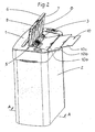
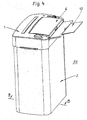
- FIG. 1 A perspective view of the new shredder "AV” with integrated unit 4 for automatic feeding of sheet material 16, 17 is in FIG. 1 shown. Further views of the shredder “AV” in various operating states are in the other figures, in particular the Fig. 2 to 5 and 7 shown schematically.
- the document shredder "AV" consists of an upper device part 1 and a lower device part 2, which is here a paper collection container.
- the upper part of the device 1 is detachably mounted on the lower device part 2.
- a unit for automatically feeding sheet material is integrated in the upper part of the device 1, see FIG. 2 .
- a recess in the formation of an intake opening 5 in the same 1 is inserted from the top of the device upper part 1 from.
- Body inward is in the end region of the intake opening 5 a paper feed 3, preferably a driven shaft with at least one driver roller, provided, see also FIG. 3 ,
- the paper feed 3 is followed by a secondary channel 12.
- This secondary channel 12 terminates, as an outgoing from the top of the device upper part 1 insertion chute 11, above the cutting rollers of the cutting unit thirteenth
- the feed opening 5 and the paper feed 3 of the integrated automatic feed unit 4 are covered with a hinged lid 6.
- To this unit 4 also includes the carrier 10 for the support of a stack of sheet material 16th
- the carrier 10 consists of several parts, the first plate 10a, the second plate 10b and the third plate 10c.
- the second plate 10b is arranged on the first plate 10a and the third plate 10c on the second plate 10b hinged or inserted.
- the carrier 10 can be pushed together or folded. In this state, it lies completely under the hinged lid 6 in the feed chute 5. There it is stored until the next use.
- the hinged lid 6 is, see Figures 2 . 3 and 6 , held with its pivot axis 6a laterally in the intake opening 5 hinged, thus hinged.
- a metal bar 7 is mounted in the lower region.
- the metal strip 7 can be replaced by other materials that withstand the load demands, provided that the front of the bar has sufficient strength and little wear.
- the shape of the staple retention tab 7 may also change, as will be explained later.
- FIG. 7 The operation and effect of the invention is in the FIG. 7 illustrated.
- Sheet material to be shredded is placed on the carrier 10a, 10b, 10c and positioned in the feed opening 5 so that the upper sheet 17 of the stack of sheet material 16 abuts against the paper feed 3, the driven shaft with drive roller.
- the hinged lid 6 of the integrated automatic feeding unit 4 is in the closed position.
- the provided on the end face 6b of the hinged lid 6 below barrier, the metal strip 7, lies with its front, outwardly directed Edge on the upper sheet 17 on.
- the or the driving rollers, 16 sheet 17 for sheet 17 in continuous feed through the secondary channel 12 is fed from the stack to the cutting unit from the stack.
- the feed direction is here marked with the reference symbol "R".
- the carrier 10 is pivotably mounted on a tilting axis 14.
- the carrier 10 when the carrier 10 is extended, that is to say the juxtaposition of its second plate 10b on the first plate 10a and the third plate 10c on the second plate 10b, its total length is subdivided into two subregions, the sections L1 and L2. It is provided that the protruding out of the body of the shredder outboard portion L2 is greater than the inner portion L1.
- the weight of lying substantially within the intake opening 5 section L1 of the carrier 10 is always smaller than the weight of the body outwardly disposed portion L2 of the carrier 10, so that the front, lying to the paper feed 3 end face of the carrier 10 always in the direction of Mit supportivewalzen of Paper feed 3 is urged.
- the tilting movement of the carrier 10 is in the Fig. 7 indicated by the double arrow 15.
- a stop provided in the FIG. 7 is shown at the double arrow 15 as an angle.
- the carrier 10 it is unnecessary for the carrier 10 to be supported from below, in this case in the area of the double arrow 15, by an energy store, in particular a compression spring.
- an energy store in particular a compression spring.
- FIGS. 6 to 6e are details of the barrier, which is preferably a metal strip 7 shown.
- the barrier which is preferably a metal strip 7 shown.
- FIG. 6 is the one in the FIG. 5 shown hinged lid 6 alone.
- a pivot axis 6a is provided, with which the hinged lid 6 in the region of the intake opening 5 on the document shredder "AV" pivotally from an open position, see FIG. 3 in a closed position, see FIG. 5 , can be worked out.
- a metal strip 7 is arranged, see FIG. 2 , which preferably extends from the left side to the right side of the hinged lid 6.
- FIG. 6a is the detail C, from the FIG. 6 , shown in more detail.
- the metal strip 7 is shown in its basic version.
- the end face 72 directed upward from the front edge 73 of its underside 71 is here at right angles to the bottom 71.
- FIG. 6b a second embodiment of the metal strip is shown.
- the end face 74 is inclined towards the body, so that between it and the bottom 71 with respect to its end edge 75 an acute angle is formed.
- FIG. 6c a third embodiment of the metal strip is shown.
- the front edge 75 directed upward end face 76 is guided concavely, preferably, the angle between it and the bottom 71 is also acute-angled.
- FIG. 6d a further embodiment of a metal strip according to the second 7a or the third 7b embodiment is shown.
- a plurality of notches 78 are provided from its front edge 77, inwards of the body 7a or 7b, so that a plurality of serrations 79 are formed.
- the free end 79a of the serrations 79, see detail D in FIG. 6e is preferably rounded, so that there are no razor-sharp tips that could result in improper operation of the hinged lid 6 to a violation of the hand of the operator.
- this further embodiment variant of the barrier the metal strip 7a, 7b, cause that in or on the retracted sheet still adhering foreign body such. As staples, paper clips, etc. are detected even safer and held back.
- the metal strip 7, 7a or 7b, at least in some areas, is magnetic. As a result, separated / cracked parts of the retracted sheet are held at the same time and do not fall unchecked on the floor next to the shredder.
Landscapes
- Engineering & Computer Science (AREA)
- Food Science & Technology (AREA)
- Crushing And Pulverization Processes (AREA)
- Sheets, Magazines, And Separation Thereof (AREA)
- Control And Other Processes For Unpacking Of Materials (AREA)
Claims (14)
- Destructeur de documents (AV) muni d'une unité intégrée (4) de délivrance automatique de matériau en forme de feuilles, notamment du papier ou des matériaux similaires,- dont la partie d'appareil supérieure (1) renferme un mécanisme de sectionnement (13), au moins un entraînement et un dispositif de commande,- sachant que, à partir de la face supérieure de ladite partie supérieure (1) de l'appareil et- à partir d'un orifice d'insertion (5) du type compartiment, occupant une position latérale, une goulotte d'introduction (11) et un canal auxiliaire (12) mènent, respectivement, audit mécanisme de sectionnement (13),- sachant qu'un couvercle rabattable (6), pouvant pivoter autour d'un axe (6a), est associé audit orifice d'insertion (5) du type compartiment, et- que la partie supérieure (1) de l'appareil repose sur une partie d'appareil inférieure (2), de préférence sur un réceptacle de papier, caractérisé par le fait- qu'une barrière est disposée dans la région du bord antérieur inférieur de la face frontale (6b) du couvercle rabattable (6), et le long dudit bord, laquelle barrière- est en applique contre la feuille supérieure de la pile de feuilles, lorsque du matériau en forme de feuilles est engagé dans l'orifice d'insertion (5) du type compartiment ; et élimine des objets, notamment des agrafes demeurant attachées dans ou sur cette feuille lors de l'insertion de cette dernière en direction du mécanisme de sectionnement (13).
- Destructeur de documents selon la revendication 1,
caractérisé par le fait
que la barrière est une barrette métallique (7) située dans la région de la face frontale (6b) du couvercle rabattable (6), sur ou dans sa face inférieure (8). - Destructeur de documents selon la revendication 2,
caractérisé par le fait
que la face extrême (72), dirigée vers le haut à partir d'une arête antérieure (73) d'une face inférieure (71) de la barrette métallique (7), décrit pour l'essentiel un angle droit avec ladite face inférieure (71). - Destructeur de documents selon la revendication 2,
caractérisé par le fait
que la face extrême (74), dirigée vers le haut à partir d'une arête antérieure (75) d'une face inférieure (71) d'une deuxième barrette métallique (7a), décrit pour l'essentiel un angle aigu avec ladite face inférieure (71). - Destructeur de documents selon la revendication 4,
caractérisé par le fait
que la face extrême antérieure (76) d'une troisième barrette métallique (7b), dirigée vers le haut, est de forme concave. - Destructeur de documents selon la revendication 2,
caractérisé par le fait
que la barrette métallique (7) est magnétique, au moins par zones. - Destructeur de documents selon la revendication 4,
caractérisé par le fait
que, dans une deuxième réalisation (7a), la barrette métallique est de configuration à dents de scie (77) sur son arête antérieure (75), et présente plusieurs dents (79) agencées avec espacement mutuel. - Destructeur de documents selon la revendication 5,
caractérisé par le fait
que, dans une troisième réalisation (7b), la barrette métallique est de configuration à dents de scie (77) sur son arête antérieure (75), et présente plusieurs dents (79) agencées avec espacement mutuel. - Destructeur de documents selon la revendication 7 ou 8,
caractérisé par le fait
que l'extrémité libre (79a) de chaque dent (79) est arrondie. - Destructeur de documents selon la revendication 1, 2, 3, 4, 5, 6, 7, 8 ou 9,
caractérisé par le fait
qu'au moins un corps, agissant comme un poids additionnel, est disposé dans la région antérieure du couvercle rabattable (6) située à proximité de la face frontale (6b), et est éloigné de l'axe de pivotement (6a) dudit couvercle. - Destructeur de documents selon la revendication 10,
caractérisé par le fait
que le corps additionnel, conférant du poids, est une pièce métallique (9) disposée, de préférence, à la face inférieure (8) du couvercle rabattable (6). - Destructeur de documents selon la revendication 10,
caractérisé par le fait
que le corps additionnel est formé de plusieurs pièces métalliques (9) fixées les unes aux autres avec espacement et disposées, de préférence, à la face inférieure (8) du couvercle rabattable (6). - Destructeur de documents selon la revendication 1,
caractérisé par le fait
qu'un accumulateur de forces exerce, sur le couvercle rabattable (6), une action telle que ce dernier (6) soit en applique sous pression, par sa barrière, sur la feuille supérieure de la pile de feuilles engagée. - Destructeur de documents selon la revendication 13,
caractérisé par le fait
que l'accumulateur de forces comprend un ou plusieurs ressort(s) et exerce, sur le couvercle rabattable (6), une action telle que ce dernier (6) soit en applique sous pression, par sa barrière, sur la feuille supérieure de la pile de feuilles engagée.
Priority Applications (1)
| Application Number | Priority Date | Filing Date | Title |
|---|---|---|---|
| PL08707579T PL2125231T3 (pl) | 2007-02-06 | 2008-02-06 | Niszczarka do papieru z zespołem doprowadzającym |
Applications Claiming Priority (3)
| Application Number | Priority Date | Filing Date | Title |
|---|---|---|---|
| CNU2007200482777U CN201012339Y (zh) | 2007-02-06 | 2007-02-06 | 一种能碎带订书钉的纸的自动连续碎纸机 |
| DE102008009236A DE102008009236B4 (de) | 2007-02-06 | 2008-02-04 | Aktenvernichter mit Zufuhr-Einheit |
| PCT/EP2008/000914 WO2008095693A1 (fr) | 2007-02-06 | 2008-02-06 | Destructeur de documents muni d'une unité d'alimentation |
Publications (2)
| Publication Number | Publication Date |
|---|---|
| EP2125231A1 EP2125231A1 (fr) | 2009-12-02 |
| EP2125231B1 true EP2125231B1 (fr) | 2010-06-30 |
Family
ID=39024123
Family Applications (1)
| Application Number | Title | Priority Date | Filing Date |
|---|---|---|---|
| EP08707579A Not-in-force EP2125231B1 (fr) | 2007-02-06 | 2008-02-06 | Destructeur de documents muni d'une unité d'alimentation |
Country Status (7)
| Country | Link |
|---|---|
| US (1) | US7721982B2 (fr) |
| EP (1) | EP2125231B1 (fr) |
| CN (1) | CN201012339Y (fr) |
| AT (1) | ATE472371T1 (fr) |
| DE (2) | DE102008009236B4 (fr) |
| PL (1) | PL2125231T3 (fr) |
| WO (1) | WO2008095693A1 (fr) |
Families Citing this family (38)
| Publication number | Priority date | Publication date | Assignee | Title |
|---|---|---|---|---|
| US8167223B2 (en) | 2007-07-13 | 2012-05-01 | Fellowes, Inc. | Shredder and auto feed system |
| US7828235B2 (en) | 2007-07-13 | 2010-11-09 | Fellowes, Inc. | Shredder auto feed system |
| US7871027B2 (en) * | 2008-02-13 | 2011-01-18 | Techko, Inc. | Auto feed shredder apparatus and methods |
| CN201239643Y (zh) * | 2008-08-06 | 2009-05-20 | 上海震旦办公设备有限公司 | 不择纸的全自动碎纸机 |
| CN201244502Y (zh) * | 2008-08-19 | 2009-05-27 | 上海震旦办公设备有限公司 | 自动碎纸机可剃钉结构 |
| US9003625B2 (en) | 2009-12-17 | 2015-04-14 | Identisys, Inc. | Shredder feeder |
| US8348185B2 (en) * | 2009-12-17 | 2013-01-08 | Identisys, Inc. | Shredder feeder |
| CN201613158U (zh) * | 2010-02-08 | 2010-10-27 | 东莞市铁志电子有限公司 | 设有旋转式盖板安全结构的碎纸机 |
| CN201618601U (zh) * | 2010-02-08 | 2010-11-03 | 东莞市铁志电子有限公司 | 带翻转式盖板的水平入纸式碎纸机 |
| USD647129S1 (en) * | 2010-04-27 | 2011-10-18 | Fellowes, Inc. | Shredder |
| KR20130045870A (ko) * | 2010-06-24 | 2013-05-06 | 로얄 소브린 인터네셔널 인코퍼레이션 | 종이 세단기 및 종이 세단 방법 |
| USD647954S1 (en) * | 2010-09-17 | 2011-11-01 | Charles Sued | Shredder |
| USD647955S1 (en) * | 2010-09-15 | 2011-11-01 | Charles Sued | Shredder |
| USD658712S1 (en) * | 2010-10-27 | 2012-05-01 | Charles Sued | Shredder |
| USD648375S1 (en) * | 2010-10-27 | 2011-11-08 | Charles Sued | Shredder |
| DE102012100681B4 (de) | 2012-01-27 | 2022-09-01 | Hermann Schwelling | Aktenvernichter mit Turbofunktion |
| DE102012106915B4 (de) | 2012-07-30 | 2020-07-16 | Hermann Schwelling | Aktenvernichter |
| US9186678B2 (en) * | 2012-10-15 | 2015-11-17 | Fellowes, Inc. | Shredder auto feed system with paper stack separation mechanism |
| USD715352S1 (en) * | 2013-01-25 | 2014-10-14 | New United Office Equipment | Shredder |
| US9409182B2 (en) | 2013-03-15 | 2016-08-09 | Fellowes, Inc. | Shredder with paper separation and advancement mechanism |
| US9669411B2 (en) | 2013-09-30 | 2017-06-06 | Fellowes, Inc. | Shredder auto feed system |
| DE102014100716A1 (de) | 2014-01-22 | 2015-07-23 | Hermann Schwelling | Einheit zum Zuführen von blattförmigem Material für einen Aktenvernichter |
| US9682381B2 (en) * | 2014-05-28 | 2017-06-20 | New United Office Equipments Co., Ltd | Shredder feeder |
| WO2016070948A1 (fr) | 2014-11-07 | 2016-05-12 | Akten-Ex Gmbh & Co Kg | Destruction de papier écrit |
| CN106179661B (zh) * | 2016-07-06 | 2018-06-26 | 广州市阳光科密电子科技有限公司 | 碎纸机 |
| CN106807517A (zh) * | 2017-01-20 | 2017-06-09 | 东莞福泰电子有限公司 | 一种自动碎纸机的盛纸盒 |
| CN106964452B (zh) * | 2017-05-02 | 2019-01-01 | 徐雪娇 | 一种碎纸机的限纸机构 |
| US10799877B2 (en) * | 2018-04-24 | 2020-10-13 | John Ward | Paper shredder support assembly |
| CN108855498B (zh) * | 2018-09-18 | 2023-08-08 | 上海震旦办公设备有限公司 | 一种具有剃钉结构的自动碎纸机及其剃钉方法 |
| US11052402B2 (en) * | 2019-02-28 | 2021-07-06 | Aurora Office Equipment Co., Ltd. Shanghai | Automatic paper shredder with staple removing structure and staple removing method using same |
| CN110064477B (zh) * | 2019-04-29 | 2021-04-06 | 杭州铭展网络科技有限公司 | 一种便于维护的碎纸机 |
| CN110328028B (zh) * | 2019-07-19 | 2021-02-26 | 肇庆市端州区科宏电子电器设备有限公司 | 一种碎纸方法 |
| CN112169952B (zh) * | 2020-10-20 | 2025-05-02 | 上海震旦办公设备有限公司 | 一种具有弯曲下纸结构的自动碎纸机 |
| USD958878S1 (en) * | 2021-09-20 | 2022-07-26 | Dongguan Suntech Electronics Co., Ltd. | Paper shredder |
| USD958877S1 (en) * | 2021-09-20 | 2022-07-26 | Dongguan Suntech Electronics Co., Ltd. | Paper shredder |
| CN114471881B (zh) * | 2022-02-25 | 2024-01-23 | 哈尔滨金源会计师事务所有限公司 | 一种会计用便捷防拼接条形碎纸机 |
| CN117299311B (zh) * | 2023-10-27 | 2025-10-28 | 上海震旦办公设备有限公司 | 一种斜插式自动碎纸机 |
| USD1068918S1 (en) * | 2024-03-25 | 2025-04-01 | Dongguan Suntech Electronics Co., Ltd. | Paper shredder |
Family Cites Families (16)
| Publication number | Priority date | Publication date | Assignee | Title |
|---|---|---|---|---|
| DE2214800C3 (de) | 1972-03-25 | 1981-05-14 | Eba-Maschinenfabrik Adolf Ehinger Kg, 7460 Balingen | Zerkleinerungsvorrichtung mit einem Schneid- oder Reißwerk |
| JPS58216747A (ja) * | 1982-06-11 | 1983-12-16 | 株式会社井上ジャパックス研究所 | シユレツダ及びシユレツダロ−ラ製作方法 |
| DE3614028A1 (de) | 1986-04-25 | 1987-10-29 | Geha Werke Gmbh | Zufuehreinrichtung fuer schriftgutvernichter |
| EP0244850B1 (fr) * | 1986-05-08 | 1991-02-27 | Sharp Kabushiki Kaisha | Déchiqueteur |
| JPH0350984Y2 (fr) * | 1986-05-13 | 1991-10-31 | ||
| DE3733412A1 (de) * | 1986-10-03 | 1988-04-14 | Sharp Kk | Papierzufuehreinrichtung und damit ausgeruesteter aktenvernichter |
| DE3780024T2 (de) | 1987-01-13 | 1992-12-24 | Sharp Kk | Zerreissmaschine. |
| JPH0440741Y2 (fr) | 1987-03-05 | 1992-09-24 | ||
| US5318228A (en) * | 1992-12-15 | 1994-06-07 | Neos Technology Inc. | Sodium dispersion and organohalide reaction processes |
| DE4408470C2 (de) * | 1993-03-22 | 1995-07-20 | Hermann Schwelling | Aktenvernichter mit schrankartigem Unterbau und haubenartigem Aufsatz |
| US5362002A (en) * | 1994-01-10 | 1994-11-08 | Tsai Shao Nong | Paper shredder with automatic paper feeding device |
| DE20023592U1 (de) * | 2000-01-26 | 2005-03-03 | Dahle Bürotechnik Gmbh | Vorrichtung zum Vernichten von gestapelt vorliegendem Blattgut |
| US7284715B2 (en) * | 2003-10-06 | 2007-10-23 | Amos Mfg., Inc. | Shredding machine |
| US7658342B2 (en) * | 2004-06-14 | 2010-02-09 | Michilin Prosperity Co., Ltd. | Auto-feed buit-in a paper shredder |
| DE102006028828A1 (de) | 2006-06-21 | 2007-12-27 | Royal Sovereign Inc. | Aktenvernichter |
| DE202007004970U1 (de) * | 2007-04-04 | 2007-09-06 | Hsm Gmbh + Co. Kg | Aktenvernichter für Zufuhr-Einheit |
-
2007
- 2007-02-06 CN CNU2007200482777U patent/CN201012339Y/zh not_active Expired - Fee Related
-
2008
- 2008-02-04 DE DE102008009236A patent/DE102008009236B4/de not_active Expired - Fee Related
- 2008-02-05 US US12/012,777 patent/US7721982B2/en not_active Expired - Fee Related
- 2008-02-06 PL PL08707579T patent/PL2125231T3/pl unknown
- 2008-02-06 AT AT08707579T patent/ATE472371T1/de active
- 2008-02-06 EP EP08707579A patent/EP2125231B1/fr not_active Not-in-force
- 2008-02-06 WO PCT/EP2008/000914 patent/WO2008095693A1/fr not_active Ceased
- 2008-02-06 DE DE502008000879T patent/DE502008000879D1/de active Active
Also Published As
| Publication number | Publication date |
|---|---|
| US20080210794A1 (en) | 2008-09-04 |
| CN201012339Y (zh) | 2008-01-30 |
| ATE472371T1 (de) | 2010-07-15 |
| WO2008095693A1 (fr) | 2008-08-14 |
| DE102008009236A1 (de) | 2008-08-07 |
| DE102008009236B4 (de) | 2011-12-15 |
| US7721982B2 (en) | 2010-05-25 |
| DE502008000879D1 (de) | 2010-08-12 |
| EP2125231A1 (fr) | 2009-12-02 |
| PL2125231T3 (pl) | 2010-12-31 |
Similar Documents
| Publication | Publication Date | Title |
|---|---|---|
| DE102008009236B4 (de) | Aktenvernichter mit Zufuhr-Einheit | |
| DE212011100080U1 (de) | Papierschredder mit Heftklammer- und Klemmenentferner | |
| DE202011110729U1 (de) | Papierschredder | |
| DE102008057137B4 (de) | Kompaktiervorrichtung | |
| DE2701897C3 (de) | Vorrichtung zum Zerkleinern von Abfällen unterschiedlicher Art, insbesondere von Industrieabfällen und Sperrmüll | |
| DE3733412A1 (de) | Papierzufuehreinrichtung und damit ausgeruesteter aktenvernichter | |
| DE2214800C3 (de) | Zerkleinerungsvorrichtung mit einem Schneid- oder Reißwerk | |
| DE10003218B4 (de) | Verfahren zum Vernichten von gestapelt vorliegendem Blattgut und Vorrichtung zur Verfahrensdurchführung | |
| EP3323603A1 (fr) | Presse à balle horizontale pourvue d'un dispositif de ficelage des ballots | |
| EP4367319A1 (fr) | Dispositif de broyage | |
| DE1803948A1 (de) | Einstellbare Brecherspitze fuer Erdbearbeitungsvorrichtungen | |
| EP2857102B1 (fr) | Procédé et dispositif de broyage de matériau en forme de feuille | |
| DE102009049070A1 (de) | Vorrichtung zum Kompaktieren von Hohlkörpern, insbesondere von Getränkeblechdosen | |
| DE3614028A1 (de) | Zufuehreinrichtung fuer schriftgutvernichter | |
| DE2612483A1 (de) | Zerkleinerungsvorrichtung mit nachgeschalteter pressvorrichtung | |
| DE102008028666A1 (de) | Zerkleinerungsvorrichtung für Lebensmittel | |
| DE202012004224U1 (de) | Rotorschere | |
| DE20380284U1 (de) | Heftvorrichtung eines Aktenordners | |
| DE20023592U1 (de) | Vorrichtung zum Vernichten von gestapelt vorliegendem Blattgut | |
| DE19718614C1 (de) | Zerkleinerungsmaschine für sperrige Gegenstände | |
| DE29707224U1 (de) | Stanz- und Bindevorrichtung | |
| DE202017101936U1 (de) | Schneidwerk mit an Abstreifelementen vorgesehenen Gegenschneiden | |
| EP2902111A1 (fr) | Unité d'introduction de matériau en forme de feuille pour une machine à détruire les documents | |
| DE58591C (de) | Längs-Scheermaschine | |
| DE1943647A1 (de) | Maschine zum Granulieren von Sperrmuell bzw. sperrigen Abfaellen jeglicher Art,wie Verpackungsemballagen od.dgl. |
Legal Events
| Date | Code | Title | Description |
|---|---|---|---|
| PUAI | Public reference made under article 153(3) epc to a published international application that has entered the european phase |
Free format text: ORIGINAL CODE: 0009012 |
|
| 17P | Request for examination filed |
Effective date: 20090826 |
|
| AK | Designated contracting states |
Kind code of ref document: A1 Designated state(s): AT BE BG CH CY CZ DE DK EE ES FI FR GB GR HR HU IE IS IT LI LT LU LV MC MT NL NO PL PT RO SE SI SK TR |
|
| GRAP | Despatch of communication of intention to grant a patent |
Free format text: ORIGINAL CODE: EPIDOSNIGR1 |
|
| DAX | Request for extension of the european patent (deleted) | ||
| GRAS | Grant fee paid |
Free format text: ORIGINAL CODE: EPIDOSNIGR3 |
|
| GRAA | (expected) grant |
Free format text: ORIGINAL CODE: 0009210 |
|
| AK | Designated contracting states |
Kind code of ref document: B1 Designated state(s): AT BE BG CH CY CZ DE DK EE ES FI FR GB GR HR HU IE IS IT LI LT LU LV MC MT NL NO PL PT RO SE SI SK TR |
|
| REG | Reference to a national code |
Ref country code: CH Ref legal event code: EP Ref country code: GB Ref legal event code: FG4D Free format text: NOT ENGLISH |
|
| REG | Reference to a national code |
Ref country code: IE Ref legal event code: FG4D Free format text: LANGUAGE OF EP DOCUMENT: GERMAN |
|
| REF | Corresponds to: |
Ref document number: 502008000879 Country of ref document: DE Date of ref document: 20100812 Kind code of ref document: P |
|
| REG | Reference to a national code |
Ref country code: NL Ref legal event code: VDEP Effective date: 20100630 |
|
| PG25 | Lapsed in a contracting state [announced via postgrant information from national office to epo] |
Ref country code: NO Free format text: LAPSE BECAUSE OF FAILURE TO SUBMIT A TRANSLATION OF THE DESCRIPTION OR TO PAY THE FEE WITHIN THE PRESCRIBED TIME-LIMIT Effective date: 20100930 Ref country code: LT Free format text: LAPSE BECAUSE OF FAILURE TO SUBMIT A TRANSLATION OF THE DESCRIPTION OR TO PAY THE FEE WITHIN THE PRESCRIBED TIME-LIMIT Effective date: 20100630 Ref country code: SE Free format text: LAPSE BECAUSE OF FAILURE TO SUBMIT A TRANSLATION OF THE DESCRIPTION OR TO PAY THE FEE WITHIN THE PRESCRIBED TIME-LIMIT Effective date: 20100630 |
|
| LTIE | Lt: invalidation of european patent or patent extension |
Effective date: 20100630 |
|
| PG25 | Lapsed in a contracting state [announced via postgrant information from national office to epo] |
Ref country code: SI Free format text: LAPSE BECAUSE OF FAILURE TO SUBMIT A TRANSLATION OF THE DESCRIPTION OR TO PAY THE FEE WITHIN THE PRESCRIBED TIME-LIMIT Effective date: 20100630 Ref country code: LV Free format text: LAPSE BECAUSE OF FAILURE TO SUBMIT A TRANSLATION OF THE DESCRIPTION OR TO PAY THE FEE WITHIN THE PRESCRIBED TIME-LIMIT Effective date: 20100630 Ref country code: HR Free format text: LAPSE BECAUSE OF FAILURE TO SUBMIT A TRANSLATION OF THE DESCRIPTION OR TO PAY THE FEE WITHIN THE PRESCRIBED TIME-LIMIT Effective date: 20100630 Ref country code: FI Free format text: LAPSE BECAUSE OF FAILURE TO SUBMIT A TRANSLATION OF THE DESCRIPTION OR TO PAY THE FEE WITHIN THE PRESCRIBED TIME-LIMIT Effective date: 20100630 |
|
| REG | Reference to a national code |
Ref country code: PL Ref legal event code: T3 |
|
| PG25 | Lapsed in a contracting state [announced via postgrant information from national office to epo] |
Ref country code: NL Free format text: LAPSE BECAUSE OF FAILURE TO SUBMIT A TRANSLATION OF THE DESCRIPTION OR TO PAY THE FEE WITHIN THE PRESCRIBED TIME-LIMIT Effective date: 20100630 Ref country code: EE Free format text: LAPSE BECAUSE OF FAILURE TO SUBMIT A TRANSLATION OF THE DESCRIPTION OR TO PAY THE FEE WITHIN THE PRESCRIBED TIME-LIMIT Effective date: 20100630 |
|
| REG | Reference to a national code |
Ref country code: IE Ref legal event code: FD4D |
|
| PG25 | Lapsed in a contracting state [announced via postgrant information from national office to epo] |
Ref country code: IS Free format text: LAPSE BECAUSE OF FAILURE TO SUBMIT A TRANSLATION OF THE DESCRIPTION OR TO PAY THE FEE WITHIN THE PRESCRIBED TIME-LIMIT Effective date: 20101030 Ref country code: SK Free format text: LAPSE BECAUSE OF FAILURE TO SUBMIT A TRANSLATION OF THE DESCRIPTION OR TO PAY THE FEE WITHIN THE PRESCRIBED TIME-LIMIT Effective date: 20100630 Ref country code: CY Free format text: LAPSE BECAUSE OF FAILURE TO SUBMIT A TRANSLATION OF THE DESCRIPTION OR TO PAY THE FEE WITHIN THE PRESCRIBED TIME-LIMIT Effective date: 20100630 Ref country code: CZ Free format text: LAPSE BECAUSE OF FAILURE TO SUBMIT A TRANSLATION OF THE DESCRIPTION OR TO PAY THE FEE WITHIN THE PRESCRIBED TIME-LIMIT Effective date: 20100630 Ref country code: RO Free format text: LAPSE BECAUSE OF FAILURE TO SUBMIT A TRANSLATION OF THE DESCRIPTION OR TO PAY THE FEE WITHIN THE PRESCRIBED TIME-LIMIT Effective date: 20100630 |
|
| PG25 | Lapsed in a contracting state [announced via postgrant information from national office to epo] |
Ref country code: IT Free format text: LAPSE BECAUSE OF FAILURE TO SUBMIT A TRANSLATION OF THE DESCRIPTION OR TO PAY THE FEE WITHIN THE PRESCRIBED TIME-LIMIT Effective date: 20100630 |
|
| PG25 | Lapsed in a contracting state [announced via postgrant information from national office to epo] |
Ref country code: IE Free format text: LAPSE BECAUSE OF FAILURE TO SUBMIT A TRANSLATION OF THE DESCRIPTION OR TO PAY THE FEE WITHIN THE PRESCRIBED TIME-LIMIT Effective date: 20100630 Ref country code: DK Free format text: LAPSE BECAUSE OF FAILURE TO SUBMIT A TRANSLATION OF THE DESCRIPTION OR TO PAY THE FEE WITHIN THE PRESCRIBED TIME-LIMIT Effective date: 20100630 |
|
| PLBE | No opposition filed within time limit |
Free format text: ORIGINAL CODE: 0009261 |
|
| STAA | Information on the status of an ep patent application or granted ep patent |
Free format text: STATUS: NO OPPOSITION FILED WITHIN TIME LIMIT |
|
| PG25 | Lapsed in a contracting state [announced via postgrant information from national office to epo] |
Ref country code: GR Free format text: LAPSE BECAUSE OF FAILURE TO SUBMIT A TRANSLATION OF THE DESCRIPTION OR TO PAY THE FEE WITHIN THE PRESCRIBED TIME-LIMIT Effective date: 20101001 |
|
| 26N | No opposition filed |
Effective date: 20110331 |
|
| PG25 | Lapsed in a contracting state [announced via postgrant information from national office to epo] |
Ref country code: ES Free format text: LAPSE BECAUSE OF FAILURE TO SUBMIT A TRANSLATION OF THE DESCRIPTION OR TO PAY THE FEE WITHIN THE PRESCRIBED TIME-LIMIT Effective date: 20101011 |
|
| REG | Reference to a national code |
Ref country code: DE Ref legal event code: R097 Ref document number: 502008000879 Country of ref document: DE Effective date: 20110330 |
|
| BERE | Be: lapsed |
Owner name: SCHWELLING, HERMANN Effective date: 20110228 |
|
| PG25 | Lapsed in a contracting state [announced via postgrant information from national office to epo] |
Ref country code: MC Free format text: LAPSE BECAUSE OF NON-PAYMENT OF DUE FEES Effective date: 20110228 |
|
| PG25 | Lapsed in a contracting state [announced via postgrant information from national office to epo] |
Ref country code: BE Free format text: LAPSE BECAUSE OF NON-PAYMENT OF DUE FEES Effective date: 20110228 |
|
| PG25 | Lapsed in a contracting state [announced via postgrant information from national office to epo] |
Ref country code: MT Free format text: LAPSE BECAUSE OF FAILURE TO SUBMIT A TRANSLATION OF THE DESCRIPTION OR TO PAY THE FEE WITHIN THE PRESCRIBED TIME-LIMIT Effective date: 20100630 |
|
| REG | Reference to a national code |
Ref country code: CH Ref legal event code: PL |
|
| PG25 | Lapsed in a contracting state [announced via postgrant information from national office to epo] |
Ref country code: LI Free format text: LAPSE BECAUSE OF NON-PAYMENT OF DUE FEES Effective date: 20120229 Ref country code: CH Free format text: LAPSE BECAUSE OF NON-PAYMENT OF DUE FEES Effective date: 20120229 |
|
| PG25 | Lapsed in a contracting state [announced via postgrant information from national office to epo] |
Ref country code: LU Free format text: LAPSE BECAUSE OF NON-PAYMENT OF DUE FEES Effective date: 20110206 |
|
| PG25 | Lapsed in a contracting state [announced via postgrant information from national office to epo] |
Ref country code: PT Free format text: LAPSE BECAUSE OF NON-PAYMENT OF DUE FEES Effective date: 20100630 |
|
| PG25 | Lapsed in a contracting state [announced via postgrant information from national office to epo] |
Ref country code: TR Free format text: LAPSE BECAUSE OF FAILURE TO SUBMIT A TRANSLATION OF THE DESCRIPTION OR TO PAY THE FEE WITHIN THE PRESCRIBED TIME-LIMIT Effective date: 20100630 Ref country code: BG Free format text: LAPSE BECAUSE OF FAILURE TO SUBMIT A TRANSLATION OF THE DESCRIPTION OR TO PAY THE FEE WITHIN THE PRESCRIBED TIME-LIMIT Effective date: 20100930 |
|
| PG25 | Lapsed in a contracting state [announced via postgrant information from national office to epo] |
Ref country code: HU Free format text: LAPSE BECAUSE OF FAILURE TO SUBMIT A TRANSLATION OF THE DESCRIPTION OR TO PAY THE FEE WITHIN THE PRESCRIBED TIME-LIMIT Effective date: 20100630 |
|
| REG | Reference to a national code |
Ref country code: AT Ref legal event code: MM01 Ref document number: 472371 Country of ref document: AT Kind code of ref document: T Effective date: 20130206 |
|
| PG25 | Lapsed in a contracting state [announced via postgrant information from national office to epo] |
Ref country code: AT Free format text: LAPSE BECAUSE OF NON-PAYMENT OF DUE FEES Effective date: 20130206 |
|
| REG | Reference to a national code |
Ref country code: DE Ref legal event code: R082 Ref document number: 502008000879 Country of ref document: DE Representative=s name: KANZLEI "REGION GOEPPINGEN" (GBR) PATENTANWALT, DE Ref country code: DE Ref legal event code: R082 Ref document number: 502008000879 Country of ref document: DE Representative=s name: WEICKMANN & WEICKMANN PATENTANWAELTE - RECHTSA, DE Ref country code: DE Ref legal event code: R082 Ref document number: 502008000879 Country of ref document: DE Representative=s name: WEICKMANN & WEICKMANN PATENT- UND RECHTSANWAEL, DE |
|
| REG | Reference to a national code |
Ref country code: FR Ref legal event code: PLFP Year of fee payment: 9 |
|
| REG | Reference to a national code |
Ref country code: DE Ref legal event code: R082 Ref document number: 502008000879 Country of ref document: DE Representative=s name: WEICKMANN & WEICKMANN PATENTANWAELTE - RECHTSA, DE Ref country code: DE Ref legal event code: R082 Ref document number: 502008000879 Country of ref document: DE Representative=s name: WEICKMANN & WEICKMANN PATENT- UND RECHTSANWAEL, DE |
|
| REG | Reference to a national code |
Ref country code: FR Ref legal event code: PLFP Year of fee payment: 10 |
|
| REG | Reference to a national code |
Ref country code: FR Ref legal event code: PLFP Year of fee payment: 11 |
|
| PGFP | Annual fee paid to national office [announced via postgrant information from national office to epo] |
Ref country code: PL Payment date: 20181231 Year of fee payment: 12 |
|
| PGFP | Annual fee paid to national office [announced via postgrant information from national office to epo] |
Ref country code: GB Payment date: 20190221 Year of fee payment: 12 Ref country code: DE Payment date: 20190227 Year of fee payment: 12 |
|
| PGFP | Annual fee paid to national office [announced via postgrant information from national office to epo] |
Ref country code: FR Payment date: 20190221 Year of fee payment: 12 |
|
| REG | Reference to a national code |
Ref country code: DE Ref legal event code: R119 Ref document number: 502008000879 Country of ref document: DE |
|
| GBPC | Gb: european patent ceased through non-payment of renewal fee |
Effective date: 20200206 |
|
| PG25 | Lapsed in a contracting state [announced via postgrant information from national office to epo] |
Ref country code: DE Free format text: LAPSE BECAUSE OF NON-PAYMENT OF DUE FEES Effective date: 20200901 Ref country code: GB Free format text: LAPSE BECAUSE OF NON-PAYMENT OF DUE FEES Effective date: 20200206 Ref country code: FR Free format text: LAPSE BECAUSE OF NON-PAYMENT OF DUE FEES Effective date: 20200229 |
|
| PG25 | Lapsed in a contracting state [announced via postgrant information from national office to epo] |
Ref country code: PL Free format text: LAPSE BECAUSE OF NON-PAYMENT OF DUE FEES Effective date: 20200206 |