EP2126178B1 - Verfahren und vorrichtung für erhöhte faserbündeldispersion mit divergierender faserzieheinheit - Google Patents
Verfahren und vorrichtung für erhöhte faserbündeldispersion mit divergierender faserzieheinheit Download PDFInfo
- Publication number
- EP2126178B1 EP2126178B1 EP08709946.1A EP08709946A EP2126178B1 EP 2126178 B1 EP2126178 B1 EP 2126178B1 EP 08709946 A EP08709946 A EP 08709946A EP 2126178 B1 EP2126178 B1 EP 2126178B1
- Authority
- EP
- European Patent Office
- Prior art keywords
- fdu
- fibers
- diverging
- diffusion chamber
- drawing slot
- Prior art date
- Legal status (The legal status is an assumption and is not a legal conclusion. Google has not performed a legal analysis and makes no representation as to the accuracy of the status listed.)
- Active
Links
Images




Classifications
-
- D—TEXTILES; PAPER
- D04—BRAIDING; LACE-MAKING; KNITTING; TRIMMINGS; NON-WOVEN FABRICS
- D04H—MAKING TEXTILE FABRICS, e.g. FROM FIBRES OR FILAMENTARY MATERIAL; FABRICS MADE BY SUCH PROCESSES OR APPARATUS, e.g. FELTS, NON-WOVEN FABRICS; COTTON-WOOL; WADDING ; NON-WOVEN FABRICS FROM STAPLE FIBRES, FILAMENTS OR YARNS, BONDED WITH AT LEAST ONE WEB-LIKE MATERIAL DURING THEIR CONSOLIDATION
- D04H3/00—Non-woven fabrics formed wholly or mainly of yarns or like filamentary material of substantial length
- D04H3/02—Non-woven fabrics formed wholly or mainly of yarns or like filamentary material of substantial length characterised by the method of forming fleeces or layers, e.g. reorientation of yarns or filaments
- D04H3/03—Non-woven fabrics formed wholly or mainly of yarns or like filamentary material of substantial length characterised by the method of forming fleeces or layers, e.g. reorientation of yarns or filaments at random
- D04H3/033—Non-woven fabrics formed wholly or mainly of yarns or like filamentary material of substantial length characterised by the method of forming fleeces or layers, e.g. reorientation of yarns or filaments at random reorientation immediately after yarn or filament formation
-
- D—TEXTILES; PAPER
- D04—BRAIDING; LACE-MAKING; KNITTING; TRIMMINGS; NON-WOVEN FABRICS
- D04H—MAKING TEXTILE FABRICS, e.g. FROM FIBRES OR FILAMENTARY MATERIAL; FABRICS MADE BY SUCH PROCESSES OR APPARATUS, e.g. FELTS, NON-WOVEN FABRICS; COTTON-WOOL; WADDING ; NON-WOVEN FABRICS FROM STAPLE FIBRES, FILAMENTS OR YARNS, BONDED WITH AT LEAST ONE WEB-LIKE MATERIAL DURING THEIR CONSOLIDATION
- D04H3/00—Non-woven fabrics formed wholly or mainly of yarns or like filamentary material of substantial length
- D04H3/08—Non-woven fabrics formed wholly or mainly of yarns or like filamentary material of substantial length characterised by the method of strengthening or consolidating
- D04H3/16—Non-woven fabrics formed wholly or mainly of yarns or like filamentary material of substantial length characterised by the method of strengthening or consolidating with bonds between thermoplastic filaments produced in association with filament formation, e.g. immediately following extrusion
-
- D—TEXTILES; PAPER
- D01—NATURAL OR MAN-MADE THREADS OR FIBRES; SPINNING
- D01D—MECHANICAL METHODS OR APPARATUS IN THE MANUFACTURE OF ARTIFICIAL FILAMENTS, THREADS, FIBRES, BRISTLES OR RIBBONS
- D01D11/00—Other features of manufacture
- D01D11/02—Opening bundles to space the threads or filaments from one another
-
- D—TEXTILES; PAPER
- D01—NATURAL OR MAN-MADE THREADS OR FIBRES; SPINNING
- D01D—MECHANICAL METHODS OR APPARATUS IN THE MANUFACTURE OF ARTIFICIAL FILAMENTS, THREADS, FIBRES, BRISTLES OR RIBBONS
- D01D5/00—Formation of filaments, threads, or the like
-
- D—TEXTILES; PAPER
- D01—NATURAL OR MAN-MADE THREADS OR FIBRES; SPINNING
- D01D—MECHANICAL METHODS OR APPARATUS IN THE MANUFACTURE OF ARTIFICIAL FILAMENTS, THREADS, FIBRES, BRISTLES OR RIBBONS
- D01D5/00—Formation of filaments, threads, or the like
- D01D5/08—Melt spinning methods
- D01D5/098—Melt spinning methods with simultaneous stretching
-
- D—TEXTILES; PAPER
- D01—NATURAL OR MAN-MADE THREADS OR FIBRES; SPINNING
- D01D—MECHANICAL METHODS OR APPARATUS IN THE MANUFACTURE OF ARTIFICIAL FILAMENTS, THREADS, FIBRES, BRISTLES OR RIBBONS
- D01D5/00—Formation of filaments, threads, or the like
- D01D5/08—Melt spinning methods
- D01D5/098—Melt spinning methods with simultaneous stretching
- D01D5/0985—Melt spinning methods with simultaneous stretching by means of a flowing gas (e.g. melt-blowing)
-
- D—TEXTILES; PAPER
- D04—BRAIDING; LACE-MAKING; KNITTING; TRIMMINGS; NON-WOVEN FABRICS
- D04H—MAKING TEXTILE FABRICS, e.g. FROM FIBRES OR FILAMENTARY MATERIAL; FABRICS MADE BY SUCH PROCESSES OR APPARATUS, e.g. FELTS, NON-WOVEN FABRICS; COTTON-WOOL; WADDING ; NON-WOVEN FABRICS FROM STAPLE FIBRES, FILAMENTS OR YARNS, BONDED WITH AT LEAST ONE WEB-LIKE MATERIAL DURING THEIR CONSOLIDATION
- D04H3/00—Non-woven fabrics formed wholly or mainly of yarns or like filamentary material of substantial length
- D04H3/02—Non-woven fabrics formed wholly or mainly of yarns or like filamentary material of substantial length characterised by the method of forming fleeces or layers, e.g. reorientation of yarns or filaments
- D04H3/03—Non-woven fabrics formed wholly or mainly of yarns or like filamentary material of substantial length characterised by the method of forming fleeces or layers, e.g. reorientation of yarns or filaments at random
Definitions
- the present invention relates to a method for forming nonwoven webs, and to an apparatus for forming such webs.
- Nonwoven fibrous webs provide tactile, comfort and aesthetic properties that approach those of traditional woven or knitted cloth materials.
- Nonwoven web materials are also widely utilized as filtration media for both liquid and gas or air filtration applications since they can be formed into a filter mesh of fine fibers having a low average pore size suitable for trapping particulate matter while still having a low pressure drop across the mesh.
- Fiber extrusion processes for spinning continuous filament yarns, filaments or fibers such as spunbond fibers, and for spinning microfibers such as meltblown fibers are well known in the art, as are the associated processes for forming nonwoven webs or fabrics therefrom.
- fibrous nonwoven webs such as spunbond nonwoven webs are formed with a fiber extrusion apparatus, such as a spinneret, and fiber attenuating apparatus, such as a fiber drawing unit (FDU), oriented in the cross-machine direction (“CD"). That is, the apparatus is oriented at a 90-degree angle to the direction of web production (the "machine direction” or "MD").
- the fibers are laid on the forming surface in a generally random manner, still, because the fibers exit the CD oriented spinneret and FDU and are deposited on the MD-moving forming surface, the resulting nonwoven webs have an overall average fiber directionality wherein more of the fibers are oriented in the MD than in the CD.
- a fiber diffuser may be positioned below the FDU to reduce the fiber velocity prior to laying the fibers onto the forming surface. It is widely recognized that such properties as material tensile strength, porosity, permeability, extensibility and material barrier, for example, are a function of the material uniformity and the directionality of the fibers or filaments in the web.
- WO 2005/045116 describes a method an apparatus for the production of nonwoven web materials wherein the fibers are attenuated with a fiber drawing unit and the velocity of the fibers is reduced in a downstream diffusion chamber defined between opposed diverging sidewalls. An electrostatic charge is applied to the fibers either before they enter the diffusion chamber or within the diffusion chamber by two or more oppositely directed electrostatic charging units.
- WO 02/052071 describes a method and apparatus for the production of nonwoven web materials wherein the fibers are subjected to an electrostatic charge and then directed to a deflector device while under the influence of the charge. The fibers are then collected on a forming surface to form the nonwoven web.
- the deflector device may include a series of teeth separated by a distance determined by the desired orientation of the fibers In the nonwoven web.
- the art is continuously seeking Improved methods and devices to still further improve the process of distributing the fibers in melt extrusion procauses to achieve superior nonwoven materials.
- the present invention relates to such an improved method and apparatus.
- WO 03/012179 discusses an open system apparatus for forming a nonwoven web according to the preamble of claim 2.
- WO 2004/104485 discloses methods and apparatus for controlling airflow in a fibre extrusion system.
- US 3334161 discloses a filament forming jet device.
- WO 2005/052238 discloses nonwoven elastic fibrous webs and methods for making them.
- JP 2002 371428 discloses yarn drawing apparatus.
- US 7008205 discloses an installation for producing spunbond fabric web whereof the diffuser is distant from the drawing slot device.
- the present invention provides a method and related apparatus for making a nonwoven web as see form in claims 1 and 2.
- the fibers may be quenched and then subjected to a pneumatic attenuation force by a drawing slot of a separate fiber draw unit (FDU) having an Inlet and an outlet, the attenuation force Imparting a velocity to the fibers and causing the fibers to be attenuated (reduced In diameter) in the quench zone.
- FDU fiber draw unit
- the quench air is provided by one or more blowers, and the pneumatic attenuation force may be generated within the separate FDU by any combination of air nozzle or plenums (referred to collectivety as air nozzles) that direct relatively high velocity aspirating air through the drawing slot.
- the FDU Is generally combined with the quench air housing such that the quench air also serves as the attenuating air.
- the quench air also serves as the attenuating air.
- some degree of attenuation of the fibers may occur in the FDU as well.
- the attenuating air streams within the drawing slot of the FDU are pertub and to further Improve the machine direction bundle spread of the fiber bundle. This may be done, for example, by alternately pulsing the air from the air nozzles in the opposits walls of the FDU. This feature may be accomplished with single or multiple air nozzles in the respective FDU walls.
- the fibers are conveyed through a diverging diffusion chamber spaced from the outlet of the FDU wherein the velocity of the fibers is reduced.
- the fibers are also subjected to an applied electrostatic charge in either the diffusion chamber or the FDU.
- the fibers exit the diffusion chamber and are collected as a web on a moving forming surface.
- Linear drawing devices, slot drawing and fiber drawing units that utilize high velocity jets to import the draw forces on the fibers are known to compress or densify the fiber bundle in the fiber/air stream. This densified or compressed fiber bundle then needs to be expanded in order to form the desired web. Diffusion devices and other types of fiber deflectors or spreading devices and electrostatics are used to expand the fibers to ensure a high level of dispersion prior to the web forming process.
- a unique feature of the method and apparatus of the invention includes conveying the fibers through a diverging profile portion of the FDU drawing slot to expand and spread the fibers in the machine direction within the FDU.
- the diverging profile causes the fiber bundle to expand and spread In the machine direction within the drawing slot prior to the inlet of the diffuser.
- This machine direction spreading of the fiber bundle within the FDU in combination with a diverging diffuser results in Improved web formation as compared to straight drawing slots (parallel sidewalls) or converging drawing slots (converging sidewalls) under comparable processing parameters.
- the diverging profile portion of the FDU drawing slot may take on various shapes.
- the diverging portion is defined by symmetrically diverging sidewalls (curved, straight, or a combination thereof) of the FDU such that a symmetric divergence angle is defined with respect to the longitudinal centerline of the drawing slot.
- the diverging portion is defined by asymmetrically diverging sidewalls, or one diverging sidewall.
- the diverging portion of the drawing slot may diverge substantially continuously (at a constant or varying rate) from a minimum width to a maximum width.
- the diverging portion may diverge in a discontinuous manner (e.g., stepwise) between the minimum and maximum width
- the diverging profile portion of the FDU drawing slot may encompass the total longitudinal length of the drawing slot.
- the drawing slot may diverge from a minimum width at the inlet of the drawing slot to a maximum width at the outlet of the drawing slot.
- the diverging profile portion may be defined only in a portion of the overall length of the drawing slot.
- the FDU drawing slot may include an upstream (with reference to the direction of fiber travel) non-diverging portion adjacent to the diverging profile portion. This non-diverging portion may have essentially parallel sidewalls, or converging sidewalls.
- the diverging profile portion of the FDU may be defined by curved wall sections, straight wall sections, or a combination of curved and straight wall sections.
- the diverging diffusion chamber may be defined by symmetrically or asymmetrically diverging sidewalls.
- the electrostatic charge is applied to the fibers as the fibers are conveyed through the FDU drawing slot by one or more electrostatic charging units.
- the charge may be applied with opposed electrostatic charging units within the FDU, with one of the electrostatic charging units located substantially closer to the diffusion chamber than the other electrostatic charging unit.
- the electrostatic charge is applied to the fibers as the fibers are conveyed through the diffusion chamber, for example by opposed electrostatic charging units within the diffusion chamber.
- polymer generally includes but is not limited to, homopolymers, copolymers, such as for example, block, graft, random and alternating copolymers, terpolymers, etc. and blends and modifications thereof.
- polymer shall include all possible geometrical configurations of the chemical formula structure. These configurations include, but are not limited to isotactic, syndiotactic and random symmetries.
- fibers refers to both staple length fibers and continuous fibers, unless otherwise indicated.
- fiber bundle refers to a grouping of individual fibers.
- nonwoven web or "nonwoven material” means a web having a structure of individual fibers or filaments which are interlaid, but not in an identifiable manner as in a knitted or woven fabric.
- Nonwoven webs may be formed from many processes, such as, for example, meltblowing processes, spunbonding processes, air-laying processes and carded web processes.
- the basis weight of nonwoven fabrics is usually expressed in grams per square meter (gsm) or ounces of material per square yard (osy), and the fiber diameters useful are usually expressed in microns.
- spunbond or "spunbond nonwoven web” refers to a nonwoven fiber or filament material of small diameter fibers that are formed by extruding molten thermoplastic polymer as fibers from a plurality of capillaries of a spinneret.
- the extruded fibers are cooled while being drawn by an eductive or other well-known drawing mechanism.
- the drawn fibers are.deposited or laid onto a forming surface in a generally random manner to form a loosely entangled fiber web, and then the laid fiber web is subjected to a bonding process to impart physical integrity and dimensional stability.
- the production of spunbond fabrics is disclosed, for example, in U.S. Pat. No. 4,340,563 to Appel et al. , U.S.
- spunbond fibers or filaments have a weight-per-unit-length in excess of about 1 denier and up to about 6 denier or higher, although both finer and heavier spunbond fibers can be produced.
- spunbond fibers often have an average diameter of larger than 7 microns, and more particularly between about 10 and about 25 microns, and up to about 30 microns or more.
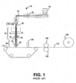
- Fig. 1 corresponds to Fig. 1 of the prior art PCT Publication No. WO 2005/045116 and is used herein to describe various conventional features of the present method and apparatus for forming a nonwoven web in a melt extrusion process.
- a process line 10 is presented for production of monocomponent or multicomponent continuous fibers.
- the process line 10 is an open system and includes an extrusion device, such as the conventional extruder 30, for melting and extruding polymer fed from polymer hopper 20.
- the polymer is fed from extruder 30 through polymer conduit 40 to a spinneret 50 that forms fibers 60, which may be monocomponent or multicomponent fibers.
- a second extruder fed from a second polymer hopper would be used.
- the spinneret 50 has openings or capillaries arranged in one or more rows.
- the spinneret openings form a downwardly extending "curtain” or “bundle” of fibers 60 when polymer is extruded through the spinneret 50.
- Spinnerets 50 for extruding multicomponent continuous fibers are well known in the art and need not be described in detail herein detail.
- An exemplary spin pack for producing multicomponent fibers is described in U.S. Pat. No. 5,989,004 to Cook .
- Polymers suitable for the present invention include the known polymers suitable for production of nonwoven webs and materials such as for example polyolefins, polyesters, polyamides, polycarbonates and copolymers and blends thereof. It should be appreciated that the particular type of polymer is not a limiting feature.
- the exemplary open process line 10 in Fig. 1 also includes a quench blower 64 positioned adjacent the curtain of fibers 60 extending from the spinneret 50. Air from the quench air blower 64 quenches the fibers 60 extending from the spinneret 50.
- the quench air can be directed from one side of the fiber curtain as shown in Fig. 1 , or both sides of the fiber curtain.
- the term "quench” simply means reducing the temperature of the fibers using a medium that is cooler than the fibers, such as, for example, chilled air streams, ambient temperature air streams, or slightly to moderately heated air streams.
- an aspirator or "fiber drawing unit” (FDU) 70 is positioned spaced from and below the spinneret 50 to receive the quenched curtain or bundle of fibers.
- the function and operation of fiber drawing units for use in melt spinning polymers are well known in the art.
- the fiber drawing unit 70 includes an elongated vertical passage or drawing slot defined by parallel side walls of the FDU 70 through which the fibers are drawn by aspirating air entering generally from both of the sides of the drawing slot and flowing downwardly through the passage.
- the attenuation chamber or fiber drawing slot is formed by opposed plates or sidewalls, designated 72 and 74 in FIG. 1 .
- the fiber drawing unit 70 utilizes a moving pneumatic stream, such as aspirating air supplied by a blower (not shown), to draw the fibers through the slot.
- the aspirating air may be heated or unheated.
- the aspirating air accelerates the fibers and applies an attenuating or drawing force on the fibers to reduce the diameter of the fibers.
- the aspirating air also acts to guide and pull the curtain or bundle of fibers through the drawing slot of the fiber drawing unit 70.
- the aspirating air may be heated, for example to activate latent helical crimp in multicomponent fibers prior to fiber laydown.
- Diffusion chambers or diffusers in general are disclosed In U.S. Pat, No. 5,814,349 to Geus et al. .
- Other diffusion chamber configurations are described in U.S. Pat Nos. 6,918,750 and 6,932,590 also to Geus et al .
- diffusion chamber 80 Is formed between the opposed diverging sidewalls 82 and 84.
- the opposed sidewalls 82 and 84 diverge outwardly toward the outlet of the chamber 80 in such a way that the volume of the chamber defined between the sidewalls expands towards the bottom end of the diffuser.
- the opposed sidewalls 82 and 84 are substantially continuous and unvented, so that air from the Jet of attenuation air does not escape from the walls of the diffusion chamber but rather exits the bottom of the diffusion chamber 80 after traveling therethrough.
- the gradually expanding or increasing volume of diffusion chamber 80 allows for the jet of fast-moving attenuation air to gradually expand Into the increasing volume as it exits the fiber drawing unit 70 and passes through the diffusion chamber 80.
- the diverging sidewalls 82 and 84 may be substantially parallel to one another In the upper portion of the diffusion chamber 80 and are Inclined or diverge at about a 5 degree angle from the vertical centerline of the chamber at the point where they begin to diverge from one another.
- the sidewalls of the diffusion chamber 80, and thus the angle of divergence, may be adjustable, and the angle of divergence may be much less than 5 degrees or may be greater than 5 degrees.
- the pneumatic jet expands in the diffusion chamber 80. it decreases in velocity, and the fiber velocity also decreases, which allows for the fiber bundle to spread out somewhat in the machine direction. That is, as the fiber bundle travels downward through the diffusion chamber, It begins to take on a machine direction dimension which is somewhat larger than ft had at the outlet of the fiber drawing unit 70.
- one or more electrostatic charging devices is used to import an electrostatic charge to the fibers of the fiber bundle either as they travel through the drawing slot of fiber drawing unit 70 or as they travel through diffusion chamber 80, or both, in Fig. 1 , exemplary electrostatic charging units 76 end 78 are shown in opposed relationship located on opposed sidewalls 72 and 74 of the fiber drawing unit 70, Where opposed electrostatic charging units are utilized, they may be configured In an offset or staggered relationship such that one electrostatic charging unit is higher or lower than the other. For example, referring to Fig.
- electrostatic charging unit 78 is mounted lower on its respective sidewall, i.e., closer to the diffusion chamber, than is electrostatic charging unit 76.
- an electrostatic charging device such as charging units 76, 78, may consist of one or more rows of electric emitter pins which produce a corona discharge, thereby imparting an electrostatic charge to the fibers, and the fibers, once charged, will tend to repel one another and help prevent groups of individual fibers from clumping or "roping" together.
- An exemplary process for charging fibers to produce nonwovens with improved fiber distribution is disclosed in PCT Pub. No. WO 02/52071 to Haynes et al. published Jul. 4, 2002 . The function and operation of such electrostatic charging devices is well known in the art and need not be described in detail herein.
- one or more electrostatic charging units may be located on the same diffusion chamber sidewall. It may also be desirable to have at least one electrostatic charging unit located on each sidewall of the diffusion chamber. Where electrostatic charging units are located on both sidewalls, they may be located substantially directly across from one another, that is, the electrostatic charging units may be located at substantially the same vertical height within diffusion chamber 80. It may also be advantageous to have the electrostatic charging units in the diffusion chamber located in a staggered configuration, similar to the staggered configuration described with respect to electrostatic charging units 76 and 78 in fiber drawing unit 70 in Fig. 1 .
- a single electrostatic charging unit may be used, In either the diffusion chamber or in the fiber drawing slot, in conjunction with specific application of aerodynamic forces to balance the repulsion forces created by the electrostatic charging unit.
- the fibers are drawn through the drawing slot of the fiber drawing unit by aspirating air entering generally from both sides of the passage, where an electrostatic charging unit is located only on one of the walls forming the drawing slot of the fiber drawing unit, the fiber bundle spread in the machine direction may be enhanced by utilizing attenuation air entering the fiber drawing unit only from the opposing sidewall of the fiber drawing slot.
- FIGS. 2A through 2G illustrate aspects of a various fiber drawing units 270 in accordance with the method and apparatus of the present Invention that may be utilized in the process line illustrated In Fig. 1 , or other suitable process lines. It should be understood that the illustrations are schematic and grossly exaggerated in order to more clearly illustrate aspects of the invention.
- a process line 200 is illustrated with an extrusion device In the form of a spinneret 250 for forming individual fibers from a molten polymer, as described above.
- Dual quench air blowers 264 are provided at the outlet of the spinneret 250.
- a fiber draw unit (FDU) 270 having an inlet 271 and an outlet 275 receives the quenched fibers.
- Attenuating air (heated or unheated) is directed into the FDU 270 by any combination of nozzles, plenums, or jets 210 (referred to collectively as nozzles).
- two nozzles 210 are provided at each wall 272, 274.
- the air supplied by the nozzles 210 is pertubated for example by pulsing or otherwise disturbing or disrupting the airstreams. This may be accomplished by the use of one or more mechanical valves that alternately pulse or modify the air flow fed to the nozzles 210. Such pertubation can be accomplished with single, dual, or other multiple arrangements of nozzles 210 within the respective walls 272, 274 of the FDU. Pertubation of drawing air is described in U.S. Pat. No. 5,807,795 to Lau et al. .
- the outlet 275 of the FDU 270 has a width generally equal to or less than the width of the inlet 286 to the diffusion chamber 280.
- the fibers exit the diffusion chamber 280 and are laid onto a traveling forming belt 212 (110 in Fig. 1 ) as a nonwoven web.
- the FDU 270 defines a drawing slot 273 that includes a diverging profile portion 277.
- the diverging profile portion is the longitudinal portion of the drawing slot 273 wherein the cross-sectional width of the slot 273 increases from a minimum to a maximum.
- the diverging profile portion 277 corresponds generally to the entire length of the drawing slot 273, with the inlet 271 of the drawing slot defining the minimum width and the outlet 275 defining the maximum width,
- the diverging profile portion 277 In this embodiment has a generally constant angle of divergence defined by symmetrically diverging sidewalls 272 and 274.
- the walls 272, 274 diverge equally over the length of the slot 273.
- the diverging profile portion 277 of the FDU causes the fibers conveyed through the drawing slot to open or expand in the machine direction prior to exiting the FDU outlet 275 and before entering the diffusion chamber 280.
- This initial machine direction spreading is believed to significantly enhance the function of the diffuser without detrimentally effecting the degree of attenuation within the FDU 270, thus having an insignificant impact on fiber size.
- the diverging profile portion 277 provides an improved nonwoven web and does not require increased energy (i.e., increased attenuating air pressure) to provide this benefit.
- the walls of the FDU 270 in Figs. 2A through 2G are illustrated as straight (non-curved), the walls, may be curved, or include a combination of curved and straight walls, to achieve the purposes of a diverging profile portion 277 of the drawing slot 273.
- Fig. 2B illustrates an embodiment of an FDU 270 wherein the diverging profile portion 277 is less than the entire length of the drawing slot 273.
- the sidewalls 272, 274 are essentially parallel from the inlet 271 to a downstream location within the FDU, at which point the walls 272, 274 diverge symmetrically to the outlet 275.
- the diverging profile portion 277 is preceded by an initial non-diverging portion of the drawing slot 273 defined by parallel sidewalls.
- the diverging profile portion 277 of Fig. 2B is defined by generally continuously diverging wall portions (straight or curved). It should be appreciated that the diverging profile portion 277 may be defined by a noncontinuous wall profile, such as a step profile. Various diverging profiles may be used to achieve the objects and function of the diverging profile portion 277 within the scope of the invention.
- the processing line 200 of Fig. 2B also incorporates one or more electrostatic charging units 276, 278 within the diverging diffusion chamber 280, as discussed above. These units may be directly opposed as illustrated in the figure, or provided in a staggered configuration. Also, it should be understood that any one of the embodiments of Figs. 2A through 2G may include any combination of charging units within the FDU 20, such as the units 276, 278 in Fig. 2C .
- Fig. 2C illustrates an embodiment of an FDU 270 wherein the diverging profile portion 277 is preceded and followed by a non-diverging portion of the drawing slot 273.
- the initial longitudinal portion of the drawing slot 273 that precedes the diverging portion has a converging profile such that the minimum width of the diverging profile portion 277 is defined at the point of maximum convergence of the initial portion.
- a nozzle is created by this unique profile that may function to accelerate the fibers before the fibers enter the diverging profile portion 277.
- the downstream non-diverging portion of the drawing slot 273 is defined by a parallel portion of the sidewalls 272, 274.
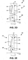
- Fig. 2D illustrates an embodiment of an FDU 270 wherein the diverging profile portion 277 is defined by asymmetrically diverging sidewalls 272, 274.
- the sidewall 274 is straight and essentially parallel to a longitudinal centerline of the drawing slot 273.
- the opposite sidewall 272 is parallel to the sidewall 274 in an upper portion of the slot 273, and then diverges to the outlet 275.
- the diverging profile of the diffusion chamber 280 is also defined by asymmetrically diverging sidewalls 282 and 284.
- the FDU 270 may have a asymmetrically diverging profile, with the diffusion chamber 280 having a symmetrically diverging profile.
- Fig. 2D is similar to that of Fig. 2E in that the sidewall 274 of the FDU 270 and sidewall 284 of the diffusion chamber 280 are straight.
- the sidewalls 274, 284 are disposed in the same plane, and may constitute a continuous wall.
- the inlet 286 of the diffusion chamber 280 is still spaced from the outlet 275 of the FDU 270 by the space between the sidewalls 272 and 282.
- Fig. 2F illustrates an embodiment of a compact or "short" process line 200 wherein the FDU 270 shorter in the longitudinal dimension as compared to the other embodiments, yet still incorporates the diverging profile portion 277.
- the longitudinal length of the drawing slot 273 may be less than the longitudinal length of the diffusion chamber 280. It should be appreciated that the benefits of the present invention may be realized on various sizes and configurations of diffusion chambers and fiber drawing units, including symmetric and asymmetric diverging walls of the fiber drawing units and/or diffusion units.
- Fig. 2G illustrates an embodiment of an FDU 270 wherein the drawing slot 273 is defined by an initial converging section of the walls 272, 274, followed by a parallel section of the walls 272, 274.
- the parallel section merges into the diverging profile portion 277 defined by asymmetrically diverging sidewalls 272, 274.
- the converging/parallel/diverging profile of the drawing slot 273 is symmetric with respect to a longitudinal centerline of the slot 273. It should be appreciated that any one or all of the different profile sections may be asymmetric as well.
- fiber drawing units may have an effective longitudinal length of the drawing slot of between about 10 inches to about 100 inches. A portion or the entire length of the drawing slot may diverge within the scope of the invention. The magnitude of divergence will thus depend on the length and divergence angle of the sidewalls, and can be readily empirically determined by those skilled in the art as a function of processing parameters.
- the diverging profile portion should have an inlet width of from about 0.125 to about 0.60 inches (about 3 to about 15mm) and that the outlet width of the divergence portion should be less than about 1.0 inches (25 mm).
- the total inclusive divergence angle (from one sidewall to the opposite sidewall) may vary within a range up to about 5 degrees, or greater.
- Fig. 3 illustrates an exemplary diverging diffusion chamber 300 bounded by generally opposed sidewalls 310 and 320. Located within each sidewall 310 and 320, respectively, is electrostatic charging unit 312 and 322. The electrostatic charging units 312 and 322 are arranged in a staggered pattern or offset configuration such that the unit 322 would be located closer to the drawing slot of the fiber drawing unit 70 ( Fig. 1 ) then electrostatic charging unit 312. In an alternate embodiment, the charging units 312, 322 may be located directly across from one another. Also, where three or more electrostatic charging units are used, they may continue the staggered pattern of Fig. 2 , or may be configured such that certain of the electrostatic charging units are located directly across from one another while other electrostatic charging units are located In a staggered pattern.
- the sidewalls of the diffusion chamber may be capable of adjustment, as is shown by adjusting rods 314, 316 and 318 attached to sidewall 310 and adjusting rods 324, 326 and 328 attached to sidewall 320.
- adjusting rods 314, 316 and 318 attached to sidewall 310
- adjusting rods 324, 326 and 328 attached to sidewall 320.
- Fig. 1 also shown is an endless foraminous forming surface such as belt 110 which is positioned below the fiber drawing unit 70 and the diffusion chamber 80 to receive the attenuated fibers 100 from the outlet opening of the diffusion chamber 80.
- a vacuum source (not shown) positioned below the foraminous forming surface 110 may be beneficially employed to pull the attenuated fibers onto foraminous forming surface 110.
- the fibers received onto foraminous forming surface 110 comprise a nonwoven web of loose continuous fibers, which may desirably be initially consolidated using consolidation means 130 to assist in transferring the web to a bonding device,
- Consolidation means 130 may be a mechanical compaction roll as is known in the art, or may be an air knife blowing heated air onto and through the web as is described in U.S. Pat, No. 5,707,468 to Arnold, et al .
- the process line 10 further Includes a bonding device such as the calender rolls 150 and 160 shown in Fig. 1 , which may be used to thermally point-bond or spot-bond the nonwoven web as described above,
- a bonding device such as the calender rolls 150 and 160 shown in Fig. 1
- through-air bonders such as are well known to those skilled in the art may be advantageously utilized.
- a through-air bonder directs a stream of heated air through the web of continuous multicomponent fibers thereby forming inter-fiber bonds by desirably utilizing heated air having a temperature at or above the polymer melting temperature of the lower melting polymer component and below the melting temperature of higher melting polymer component.
- the web may be bonded by utilizing other means known In the art, such as adhesive bonding means, ultrasonic bonding means or entanglement means such as hydroentangling or needling.
- the process line 10 further Includes a winding roll 180 for taking up the bonded web 170. While not shown here, various additional potential processing and/or finishing steps known in the art such as web slitting, stretching, treating, or lamination of the nonwoven fabric Into a composite with other materials, such as films or other nonwoven layers, may be performed without departing from the scope of the invention.
- the uniformity of the nonwoven web formation may be further improved or enhanced by utilizing vortex generators on or near the inner surface of the diverging sidewalls of the diffusion chamber.
- Vortex generators may be placed along one or more walls at spaced apart locations across the cross machine direction of the sidewall, to induce vortices into the alrstream.
- the vortices induced will act to increase turbulence in the inner layer of the airstream close to the sidewall, adding energy to the now in that area, and reduce flow separation, allowing for the airstream to more effectively conform to the sidewalls as the sidewalls diverge, and thus providing for a more complete machine direction dispersion of the airstream and consequently a larger machine direction fiber bundle spread.
- Vortices may be generated by having tabs or protrusions on one or more sidewalls at spaced apart locations, such as are described in U.S. Pat No. 5,695,377 to Triebes et al. .
- catching or dragging of the fibers upon the vortex generators may be an issue.
- one or more backward facing steps running substantially In the cross-machine direction width of the diffusion chamber may be used on the inner sidewall surface to generate vortices.
- air jets may be used on one or both sidewalls of the diffusion chamber at or near the point of divergence to generate vortices by blowing fine jets of a fluid such as air through pores or holes drilled or otherwise formed in the sidewall surface material,
- synthetic jets such as are generally described in U. S. Pat. No. 5,986 , 522 to Glazer et al. , may be used on one or both sidewalls to generate vortices.
- a synthetic Jet may be produced from a fluid-filled chamber having a flexible actuatable membrane at one end and a more rigid wall at the other end, the rigid wall having a small hole.
- the flexible membrane may then be repeatedly actuated by acoustical wave energy, mechanical energy or piezoelectric energy, thereby causing a jet of fluid (such as air) to emanate from the hole in the more rigid wall at the other end of the chamber.
- Example spunbond nonwoven materials were produced using commercially available isotactic polypropylene of approximately 35 melt flow rate, available from ExxonMobil Chemical Co. (Houston, Texas) and designated as Exxon 3155. All materials were produced using a spunbond type slot-draw nonwoven spinning system such as described in the above-mentioned U.S. Pat. No. 3,802,817 to Matsuki et al . and, after being collected on a forming surface, all materials were thermally bonded using a heated calendar roll. For all the materials, an electrostatic charging system was located near the drawing slot exit of the fiber drawing unit to charge the filament curtain, as generally described in the PCT Pub. No. WO 2005/045116 cited above, wherein the fibers were subjected to an applied electrostatic charge before the fibers entered the diffusion chamber.
- a diffusion chamber substantially as described in U.S. Pat. No. 5,814,349 to Geus et al . and as generally described above (except that no electrostatic charging units were located within the diffuser) was located below the fiber drawing unit drawing slot.
- the diffusion chamber was mounted slightly lower than the exit of the fiber drawing unit to allow for air to be drawn into the diffusion chamber.
- the diffusion chamber was set up using control rods to produce a venturi shape, with the sidewalls initially converging before diverging out at the bottom or exit of the diffusion chamber.
- the control samples were produced using a Fiber Drawing Unit (FDU) with parallel sidewalls that established an entrance opening and an exit opening on the FDU of the same dimension.
- the example materials were produced using a FDU with diverging sidewalls that established an exit opening greater than the entrance opening dimension.
- One set of example materials was produced using an electrostatic charging system to impart a charge on the fibers. For all materials, the spinning and drawing conditions were held constant. The polymer throughput rate, the fiber drawing rates were held constant thereby resulting in the same fiber size. For all materials, the fibers had an average diameter of about 18 microns (about 2.0 denier).
- the formed nonwoven webs were tested for Air Permeability according to the ASTM D737 test method, and using a TEXTEST FX 3300 Air Permeability tester available from the Schmid Corp. (Spartanburg, SC), The materials were tested for air permeability and the results of fifteen repetitions for each sample were averaged for each material.
- air permeability Is a measure of airflow through the Spunbond Web. Higher numbers indicate a lower pressure drop. Pressure drop is a direct indicator of web formation. Better formation materials have smaller pore structure, which causes the pressure drop to increase. Therefore better formation is Indicated by lower Permeability values.
- the data in Table 1 shows that the permeability values for the diverging FDU samples are ⁇ 11 % to 13% lower than the comparative materials. All materials listed in TABLE were the same basis weight, about 0.50 osy (about 17 gsm), and were produced at the same polymer throughput rate, of about 10.6 PIH (about 190 kg/meter/hour). The results indicate that, with all other parameters being essentially constant, the diverging FDU produces a better-formed web.
Landscapes
- Engineering & Computer Science (AREA)
- Textile Engineering (AREA)
- Mechanical Engineering (AREA)
- Nonwoven Fabrics (AREA)
- Spinning Methods And Devices For Manufacturing Artificial Fibers (AREA)
Claims (15)
- Offensystem-Verfahren für Schmelzexkursion zur Herstellung einer Vliesbahn, wobei das Verfahren umfasst:Bereitstellen einer Vielzahl von Fasern (60) aus einer Exkursionsvorrichtung (250);Aussetzen der Fasern (60) einer pneumatischen Dämpfungskraft mit einem Zugschlitz (273) einer Offensystem-Faserzugeinheit (FDU) (270), welche einen Einlass (271) und einen Auslass (275) aufweist, wobei die Dämpfungskraft den Fasern (60) eine Geschwindigkeit verleiht;Befördern der Fasern (60) durch einen sich weitenden Profilteil (277) des FDA Zugschlitzes (273), um die Fasern in der Maschinenrichtung innerhalb der FDU (270) zu verteilen;Verringern der Geschwindigkeit der Fasern in einer sich weitenden Diffusionskammer (280), welche von dem Auslass (275) der FDU (270) beabstandet ist;Aussetzen der Fasern (60) einer aufgebrachten elektrostatischen Ladung entweder in der Diffusionskammer (280) oder der FDU (270); unddanach Sammeln der Fasern (60) zu einer Bahn (170) auf einer sich bewegenden Formieroberfläche (110):wobei das Verfahren weiterhin umfasst:Zuführen von Dämpfungsluft zu dem Zugschlitz (273) in der FDU (270) mit einer oder mehreren Luftdüsen (210), welche in jeweiligen gegenüberliegenden Seitenwänden der FDU (270) eingerichtet sind; undVerwirbeln der Dämpfungsluft, welche den Luftdüsen (210) zugeführt wird.
- Offensystem-Vorrichtung zum Bilden einer Vliesbahn, welche umfasst:eine Extrusionsvorrichtung (30), welche eine Vielzahl von Fasern (60) bereitstellt; undeine Offensystem-Faserzugeinheit (FDU) (270), welche angeordnet ist, um die Vielzahl von Fasern (60) von der Exkursionsvorrichtung (30) zu empfangen, wobei die FDU (270) einen Zugschlitz (273) beinhaltet, in welchem die Fasern (60) gedämpft werden, wobei der Zugschlitz (273) einen Einlass (271) und einen Auslass (275) aufweist, bestimmt durch beabstandete Wände (272, 274);wobei zumindest ein Längsteil des Zugschlitzes (273) ein sich weitendes Profil (277) in einer Richtung der Fasernbeförderung durch die FDU (270) umfasst, wobei die Fasern (60) sich in einer Maschinenrichtung verteilen, während sie durch den sich weitenden Profilteil (277) der FDU (270) bewegt werden;gekennzeichnet durch weiteres Umfassen einer sich weitenden Diffusionskammer (280), die von dem Auslass (275) der FDU (270) beabstandet ist;
wobei mindestens eine elektrostatische Ladungseinheit (276, 278) eingerichtet ist, eine elektrostatische Ladung auf die Fasern (60) entweder in der Diffusionskammer (280) oder der FDU (270) anzuwenden;wobei mindestens eine Luftdüse (210) in der FDU eingerichtet ist, Dämpfungsluft zu dem sich weitenden Profilteil (277) des FDU-Zugschlitzes (273) zuzuführen,wobei die mindestens eine Luftdüse (210) eingerichtet ist, die Dämpfungsluft, die von der Luftdüse (210) zugeführt wird, zu verwirbeln; undeine sich bewegende Formieroberfläche (110) unterhalb der Diffusionskammer (280), auf welcher die Fasern (60) gesammelt werden. - Erfindung gemäß Anspruch 1 oder 2, bei die elektrostatische Ladungseinheit (276, 278) innerhalb der FDU (270) eingerichtet ist, die elektrostatische Ladung anzuwenden während die Fasern (60) durch den Zugschlitz (273) befördert werden.
- Erfindung gemäß Anspruch 3, welche gegenüberliegende elektrostatische Ladungseinheiten (276, 278) innerhalb der FDU (270) umfasst, wobei mindestens eine der elektrostatischen Ladungseinheiten (276, 278) im Wesentlichen näher an der Diffusionskammer (280) angeordnet ist als mindestens eine andere der elektrostatischen Ladungseinheiten (276, 278).
- Erfindung gemäß Anspruch 1 oder 2, wobei die elektrostatische Ladungseinheit (276, 278) innerhalb der Diffusionskammer (280) angeordnet ist.
- Erfindung gemäß Anspruch 5, welche gegenüberliegende elektrostatische Ladungseinheiten (276, 278) innerhalb der Diffusionskammer (280) umfasst.
- Erfindung gemäß Anspruch 1 oder 2, wobei die sich weitende Diffusionskammer (280) durch gegenüberliegende symmetrisch sich weitende Seitenwände definiert ist, oder wobei die sich weitende Diffusionskammer (280) durch asymmetrisch sich weitende Seitenwände definiert ist.
- Erfindung gemäß Anspruch 1 oder 2, wobei der sich weitende Profilteil (277) des FDU-Zugschlitzes (273) durch sich symmetrisch weitende Seitenwände (272, 274) definiert ist, oder wobei der sich weitende Profilteil (277) des FDU-Zugschlitzes (273) durch sich asymmetrisch weitende Seitenwände (272, 274) definiert ist.
- Erfindung gemäß Anspruch 1 oder 2, wobei der sich weitende Profilteil (277) des FDU-Zugschlitzes (273) sich im Wesentlichen kontinuierlich zwischen dem Zugschlitz-Einlass (271) und dem Zugschlitz-Auslass (275) weitet, oder wobei der sich weitende Profilteil (277) des FDU-Zugschlitzes (273) sich diskontinuierlich weitet, oder wobei der FDU-Zugschlitz (273) einen vorgelagerten sich nicht weitenden Teil angrenzend an den sich weitenden Profilteil (277) umfasst.
- Erfindung gemäß Anspruch 9, wobei der sich nicht weitende Teil durch im Wesentlichen parallele Seitenwände definiert ist.
- Erfindung gemäß Anspruch 1 oder 2, wobei der sich nicht weitende Teil durch konvergierende Seitenwände definiert ist.
- Erfindung gemäß Anspruch 2, welche mindestens eine Luftdüse umfasst, die innerhalb jeder der jeweiligen Wände (272, 274) der FDU (270) eingerichtet ist.
- Erfindung gemäß Anspruch 1 oder 2, wobei der sich weitende Profilteil (277) des FDU-Zugschlitzes (273) eine Einlassbreite von ungefähr 0,125 Inch (3,2 mm) bis ungefähr 0,6 Inch (15 mm) aufweist, und eine Auslassbreite von größer als der Einlassbreite und weniger als ungefähr 1,0 Inch (20,4 mm) aufweist, und oder wobei die FDU eine Längslänge von zwischen ungefähr 10,0 Inch (2,54 cm) bis ungefähr 100,0 Inch (2,54 m) aufweist.
- Erfindung gemäß Anspruch 13, wobei die FDU (270) eine geringere Längslänge als eine Längslänge der Diffusionskammer (280) aufweist.
- Erfindung gemäß Anspruch 1 oder 2, bei der sich weitende Profilteil (277) des FDU-Zugschlitzes (273) einen Gesamtinklusiv-Weitungswinkel von bis zu ungefähr 5 Grad aufweist.
Applications Claiming Priority (2)
| Application Number | Priority Date | Filing Date | Title |
|---|---|---|---|
| US11/725,593 US8246898B2 (en) | 2007-03-19 | 2007-03-19 | Method and apparatus for enhanced fiber bundle dispersion with a divergent fiber draw unit |
| PCT/IB2008/050367 WO2008114156A1 (en) | 2007-03-19 | 2008-01-31 | Method and apparatus for enhanced fiber bundle dispersion with a divergent fiber draw unit |
Publications (2)
| Publication Number | Publication Date |
|---|---|
| EP2126178A1 EP2126178A1 (de) | 2009-12-02 |
| EP2126178B1 true EP2126178B1 (de) | 2014-12-24 |
Family
ID=39616547
Family Applications (1)
| Application Number | Title | Priority Date | Filing Date |
|---|---|---|---|
| EP08709946.1A Active EP2126178B1 (de) | 2007-03-19 | 2008-01-31 | Verfahren und vorrichtung für erhöhte faserbündeldispersion mit divergierender faserzieheinheit |
Country Status (8)
| Country | Link |
|---|---|
| US (2) | US8246898B2 (de) |
| EP (1) | EP2126178B1 (de) |
| KR (1) | KR101492282B1 (de) |
| CN (1) | CN101636532B (de) |
| AU (1) | AU2008227978B2 (de) |
| BR (1) | BRPI0808253B8 (de) |
| MX (1) | MX2009010006A (de) |
| WO (1) | WO2008114156A1 (de) |
Cited By (1)
| Publication number | Priority date | Publication date | Assignee | Title |
|---|---|---|---|---|
| EP4115008A1 (de) | 2020-03-05 | 2023-01-11 | Kimberly-Clark Worldwide, Inc. | Verbessertes spinnvliessystem und verfahren |
Families Citing this family (18)
| Publication number | Priority date | Publication date | Assignee | Title |
|---|---|---|---|---|
| US8246898B2 (en) * | 2007-03-19 | 2012-08-21 | Conrad John H | Method and apparatus for enhanced fiber bundle dispersion with a divergent fiber draw unit |
| WO2009013107A2 (de) * | 2007-07-25 | 2009-01-29 | Oerlikon Heberlein Temco Gmbh | Vorrichtung zur behandlung eines multifilen fadens |
| CN103210133B (zh) * | 2010-08-12 | 2017-04-19 | 波玛工程有限公司 | 用于对纤维进行纺织且特别是用于生产含有纤维的非纺织品的工艺和设备 |
| EP2912222B1 (de) * | 2012-10-27 | 2017-03-29 | Oerlikon Textile GmbH & Co. KG | Vorrichtung zur herstellung eines spinnvlieses |
| EP2738297B1 (de) * | 2012-12-03 | 2016-03-02 | Reifenhäuser GmbH & Co. KG Maschinenfabrik | Vorrichtung und Verfahren zur Herstellung einer Spinnvliesbahn aus Filamenten |
| AU2012397883B2 (en) * | 2012-12-27 | 2016-01-14 | Sca Hygiene Products Ab | Hydroformed composite nonwoven |
| US10494743B2 (en) | 2015-04-08 | 2019-12-03 | Columbia Insurance Company | Yarn texturizing apparatus and method |
| US20170268135A1 (en) * | 2016-03-21 | 2017-09-21 | Ford Global Technologies, Llc | Method of separating fiber tows |
| CN106409525B (zh) * | 2016-10-11 | 2018-05-18 | 中国科学院山西煤炭化学研究所 | 石墨烯、导电性纤维复合材料及其与多级孔碳复合材料的制备方法、其产品及应用 |
| SI3382081T1 (sl) * | 2017-03-31 | 2020-01-31 | Reifenhaeuser Gmbh & Co. Kg Maschinenfabrik | Naprava za proizvodnjo tkanih polsti iz brezkončnih filamentov |
| WO2019006242A2 (en) | 2017-06-30 | 2019-01-03 | Kimberly-Clark Worldwide, Inc. | METHODS OF MANUFACTURING COMPOSITE NONWOVEN STRIPS |
| US11097453B2 (en) | 2017-10-23 | 2021-08-24 | Neuvotec, Llc | Hinge mold process for creating structural forms and shapes |
| JP7525399B2 (ja) | 2017-11-22 | 2024-07-30 | エクストルージョン グループ,エルエルシー | メルトブローンダイチップアセンブリ及び方法 |
| KR102391138B1 (ko) * | 2018-03-29 | 2022-04-28 | 도레이 카부시키가이샤 | 연신 장치, 그리고 섬유 및 섬유 웹의 제조 장치 및 제조 방법 |
| PL3771760T3 (pl) * | 2019-07-30 | 2023-09-11 | Asahi Kasei Kabushiki Kaisha | Sposób i urządzenie do wytwarzania włókniny wykonanej z karbikowanych włókien syntetycznych |
| CN111648125B (zh) * | 2020-05-23 | 2022-07-08 | 江苏索盈节能环保设备有限公司 | 一种用于熔喷布静电添加的导布辊式驻极机 |
| CN114000263B (zh) * | 2021-11-22 | 2022-09-27 | 江苏英伟医疗有限公司 | 全自动生产抗落絮无纺布的方法及临床全防护医用手术单 |
| CN114150439A (zh) * | 2021-11-29 | 2022-03-08 | 厦门当盛新材料有限公司 | 闪蒸纺丝丝束网的牵伸装置及闪蒸纺丝设备 |
Family Cites Families (88)
| Publication number | Priority date | Publication date | Assignee | Title |
|---|---|---|---|---|
| US3334161A (en) | 1965-02-10 | 1967-08-01 | Du Pont | Filament forwarding jet device |
| US3325906A (en) | 1965-02-10 | 1967-06-20 | Du Pont | Process and apparatus for conveying continuous filaments |
| DE2048006B2 (de) | 1969-10-01 | 1980-10-30 | Asahi Kasei Kogyo K.K., Osaka (Japan) | Verfahren und Vorrichtung zur Herstellung einer breiten Vliesbahn |
| DE1950669C3 (de) | 1969-10-08 | 1982-05-13 | Metallgesellschaft Ag, 6000 Frankfurt | Verfahren zur Vliesherstellung |
| US4186463A (en) * | 1974-09-17 | 1980-02-05 | The Kendall Company | Apparatus for making biaxially oriented nonwoven fabrics and method of making same |
| US4209563A (en) | 1975-06-06 | 1980-06-24 | The Procter & Gamble Company | Method for making random laid bonded continuous filament cloth |
| US4350482A (en) | 1978-11-03 | 1982-09-21 | Alexandrov Vyacheslav S | Apparatus for production of fibrous sheet material |
| US4263241A (en) | 1978-11-03 | 1981-04-21 | Alexandrov Vyacheslav S | Method for production of fibrous sheet material and apparatus for carrying out the same |
| US4340563A (en) | 1980-05-05 | 1982-07-20 | Kimberly-Clark Corporation | Method for forming nonwoven webs |
| US4405297A (en) | 1980-05-05 | 1983-09-20 | Kimberly-Clark Corporation | Apparatus for forming nonwoven webs |
| US4322027A (en) | 1980-10-02 | 1982-03-30 | Crown Zellerbach Corporation | Filament draw nozzle |
| DE3401639A1 (de) | 1984-01-19 | 1985-07-25 | Hoechst Ag, 6230 Frankfurt | Vorrichtung zum herstellen eines spinnvlieses |
| DE3503818C1 (de) | 1985-02-05 | 1986-04-30 | Reifenhäuser GmbH & Co Maschinenfabrik, 5210 Troisdorf | Vorrichtung zum Verstrecken von Monofilfadenbuendeln |
| US5141700A (en) | 1986-04-30 | 1992-08-25 | E. I. Du Pont De Nemours And Company | Melt spinning process for polyamide industrial filaments |
| DE3701531A1 (de) | 1987-01-21 | 1988-08-04 | Reifenhaeuser Masch | Verfahren und anlage zur herstellung von einem spinnvlies |
| DE3713862A1 (de) | 1987-04-25 | 1988-11-10 | Reifenhaeuser Masch | Verfahren und spinnvliesanlage zur herstellung eines spinnvlieses aus synthetischem endlosfilament |
| US5208098A (en) | 1990-10-23 | 1993-05-04 | Amoco Corporation | Self-bonded nonwoven web and porous film composites |
| US5292239A (en) * | 1992-06-01 | 1994-03-08 | Fiberweb North America, Inc. | Apparatus for producing nonwoven fabric |
| US5482772A (en) | 1992-12-28 | 1996-01-09 | Kimberly-Clark Corporation | Polymeric strands including a propylene polymer composition and nonwoven fabric and articles made therewith |
| DE4312419C2 (de) | 1993-04-16 | 1996-02-22 | Reifenhaeuser Masch | Anlage für die Herstellung einer Spinnvliesbahn aus aerodynamischen verstreckten Filamenten aus Kunststoff |
| CA2105026C (en) * | 1993-04-29 | 2003-12-16 | Henry Louis Griesbach Iii | Shaped nonwoven fabric and method for making the same |
| DE4409940A1 (de) | 1994-03-23 | 1995-10-12 | Hoechst Ag | Verfahren zum Verstrecken von Filamentbündeln in Form eines Fadenvorhanges, dafür geeignete Vorrichtung sowie deren Verwendung zur Herstellung von Spinnvliesen |
| DE4414277C1 (de) | 1994-04-23 | 1995-08-31 | Reifenhaeuser Masch | Nach dem Ruhedruckprinzip arbeitende Spinnvliesanlage für die Herstellung einer Nonwoven-Spinnvliesbahn |
| US5558713A (en) * | 1994-10-31 | 1996-09-24 | The Procter & Gamble Company | Method and apparatus for forming a pulsed stream of particles for application to a fibrous web |
| US6183684B1 (en) | 1994-12-15 | 2001-02-06 | Ason Engineering, Ltd. | Apparatus and method for producing non-woven webs with high filament velocity |
| US5545371A (en) | 1994-12-15 | 1996-08-13 | Ason Engineering, Inc. | Process for producing non-woven webs |
| US5707468A (en) | 1994-12-22 | 1998-01-13 | Kimberly-Clark Worldwide, Inc. | Compaction-free method of increasing the integrity of a nonwoven web |
| DE19504953C2 (de) | 1995-02-15 | 1999-05-20 | Reifenhaeuser Masch | Anlage für die Herstellung einer Spinnvliesbahn aus thermoplastischen Endlosfäden |
| US5648041A (en) * | 1995-05-05 | 1997-07-15 | Conoco Inc. | Process and apparatus for collecting fibers blow spun from solvated mesophase pitch |
| US5758823A (en) | 1995-06-12 | 1998-06-02 | Georgia Tech Research Corporation | Synthetic jet actuator and applications thereof |
| US5811178A (en) | 1995-08-02 | 1998-09-22 | Kimberly-Clark Worldwide, Inc. | High bulk nonwoven sorbent with fiber density gradient |
| US5711970A (en) | 1995-08-02 | 1998-01-27 | Kimberly-Clark Worldwide, Inc. | Apparatus for the production of fibers and materials having enhanced characteristics |
| US5667749A (en) | 1995-08-02 | 1997-09-16 | Kimberly-Clark Worldwide, Inc. | Method for the production of fibers and materials having enhanced characteristics |
| AU7163596A (en) | 1995-10-30 | 1997-05-22 | Kimberly-Clark Corporation | Fiber spin pack |
| DE19620379C2 (de) | 1996-05-21 | 1998-08-13 | Reifenhaeuser Masch | Anlage zur kontinuierlichen Herstellung einer Spinnvliesbahn |
| US5895710A (en) * | 1996-07-10 | 1999-04-20 | Kimberly-Clark Worldwide, Inc. | Process for producing fine fibers and fabrics thereof |
| US5695377A (en) | 1996-10-29 | 1997-12-09 | Kimberly-Clark Worldwide, Inc. | Nonwoven fabrics having improved fiber twisting and crimping |
| US5762857A (en) * | 1997-01-31 | 1998-06-09 | Weng; Jian | Method for producing nonwoven web using pulsed electrostatic charge |
| US5876840A (en) * | 1997-09-30 | 1999-03-02 | Kimberly-Clark Worldwide, Inc. | Crimp enhancement additive for multicomponent filaments |
| FR2792656B1 (fr) | 1999-04-23 | 2001-06-01 | Icbt Perfojet Sa | Dispositif permettant d'assurer l'ouverture et la repartition d'un faisceau de filaments lors de la realisation d'une nappe textile non tissee |
| US6379136B1 (en) | 1999-06-09 | 2002-04-30 | Gerald C. Najour | Apparatus for production of sub-denier spunbond nonwovens |
| JP3623402B2 (ja) | 1999-07-15 | 2005-02-23 | ユニ・チャーム株式会社 | 冷却延伸装置 |
| AU7725301A (en) | 2000-08-03 | 2002-02-18 | Bba Nonwovens Simpsonville Inc | Process and system for producing multicomponent spunbonded nonwoven fabrics |
| FR2815647B1 (fr) | 2000-10-20 | 2003-02-14 | Rieter Perfojet | Installation de production d'une nappe non tissee a difusseur et a separation des filaments par voie electrostatique |
| FR2815646B1 (fr) | 2000-10-20 | 2003-01-10 | Rieter Perfojet | Installation de production d'une nappe non tissee dont le diffuseur est a distance du dispositif a fente d'etirage |
| US6607624B2 (en) | 2000-11-20 | 2003-08-19 | 3M Innovative Properties Company | Fiber-forming process |
| JP3964788B2 (ja) | 2000-11-20 | 2007-08-22 | スリーエム イノベイティブ プロパティズ カンパニー | 繊維形成プロセス |
| US20030003834A1 (en) * | 2000-11-20 | 2003-01-02 | 3M Innovative Properties Company | Method for forming spread nonwoven webs |
| US6709623B2 (en) | 2000-12-22 | 2004-03-23 | Kimberly-Clark Worldwide, Inc. | Process of and apparatus for making a nonwoven web |
| US7179412B1 (en) * | 2001-01-12 | 2007-02-20 | Hills, Inc. | Method and apparatus for producing polymer fibers and fabrics including multiple polymer components in a closed system |
| JP2002302862A (ja) * | 2001-04-06 | 2002-10-18 | Mitsui Chemicals Inc | 不織布の製造方法及び装置 |
| FR2825381B1 (fr) | 2001-05-31 | 2003-11-14 | Rieter Perfojet | Installation de production d'une nappe non tissee a poids tres regulier |
| JP2002371428A (ja) * | 2001-06-08 | 2002-12-26 | Kobe Steel Ltd | 糸条延伸装置 |
| US6660218B2 (en) | 2001-07-31 | 2003-12-09 | E.I. Du Pont De Nemours And Company | Filament draw jet apparatus and process |
| DK1432861T4 (da) | 2001-09-26 | 2012-02-13 | Fiberweb Simpsonville Inc | Apparat og fremgangsmåde til fremstilling af en ikke-vævet bane af filamenter |
| US20030114066A1 (en) | 2001-12-13 | 2003-06-19 | Clark Darryl Franklin | Uniform distribution of absorbents in a thermoplastic web |
| US20030118816A1 (en) | 2001-12-21 | 2003-06-26 | Polanco Braulio A. | High loft low density nonwoven webs of crimped filaments and methods of making same |
| US6799957B2 (en) | 2002-02-07 | 2004-10-05 | Nordson Corporation | Forming system for the manufacture of thermoplastic nonwoven webs and laminates |
| DE50211736D1 (de) | 2002-02-28 | 2008-04-03 | Reifenhaeuser Gmbh & Co Kg | Anlage zur kontinuierlichen Herstellung einer Spinnvliesbahn |
| TR200302088T3 (tr) * | 2002-02-28 | 2004-01-21 | Reifenhauser Gmbh&Co. Maschinenfabrik | Bir dokuma yün hattının sürekli imalatı için tesis |
| US7488441B2 (en) | 2002-06-15 | 2009-02-10 | Kimberly-Clark Worldwide, Inc. | Use of a pulsating power supply for electrostatic charging of nonwovens |
| EP1573107B1 (de) * | 2002-10-24 | 2009-12-02 | Dow Global Technologies Inc. | Elastomere mehrkomponentenfasern,vliesbahnen und vliesstoffe |
| US7014441B2 (en) | 2002-11-01 | 2006-03-21 | Kimberly-Clark Worldwide, Inc. | Fiber draw unit nozzles for use in polymer fiber production |
| US6989125B2 (en) | 2002-11-21 | 2006-01-24 | Kimberly-Clark Worldwide, Inc. | Process of making a nonwoven web |
| US20040116018A1 (en) | 2002-12-17 | 2004-06-17 | Kimberly-Clark Worldwide, Inc. | Method of making fibers, nonwoven fabrics, porous films and foams that include skin treatment additives |
| US7018188B2 (en) * | 2003-04-08 | 2006-03-28 | The Procter & Gamble Company | Apparatus for forming fibers |
| US7037097B2 (en) | 2003-05-20 | 2006-05-02 | Hills, Inc. | Methods and apparatus for controlling airflow in a fiber extrusion system |
| US7504060B2 (en) | 2003-10-16 | 2009-03-17 | Kimberly-Clark Worldwide, Inc. | Method and apparatus for the production of nonwoven web materials |
| US20050087900A1 (en) | 2003-10-23 | 2005-04-28 | Nordson Corporation | Spundbonding spin pack characterized by uniform polymer distribution and method of use |
| US8333918B2 (en) * | 2003-10-27 | 2012-12-18 | Kimberly-Clark Worldwide, Inc. | Method for the production of nonwoven web materials |
| US20050087288A1 (en) | 2003-10-27 | 2005-04-28 | Haynes Bryan D. | Method and apparatus for production of nonwoven webs |
| US7172398B2 (en) | 2003-11-17 | 2007-02-06 | Aktiengesellschaft Adolph Saurer | Stabilized filament drawing device for a meltspinning apparatus and meltspinning apparatus including such stabilized filament drawing devices |
| US20050106982A1 (en) | 2003-11-17 | 2005-05-19 | 3M Innovative Properties Company | Nonwoven elastic fibrous webs and methods for making them |
| US7320581B2 (en) | 2003-11-17 | 2008-01-22 | Aktiengesellschaft Adolph Saurer | Stabilized filament drawing device for a meltspinning apparatus |
| US20060049549A1 (en) | 2004-08-12 | 2006-03-09 | Anders Moller | Method for improving formation and properties of spunbond fabric |
| DE502005006763D1 (de) * | 2004-09-24 | 2009-04-16 | Oerlikon Textile Gmbh & Co Kg | Vorrichtung zur ablage von synthetischen fasern zu einem vlies |
| DE502005010024D1 (de) * | 2005-02-04 | 2010-09-09 | Oerlikon Textile Gmbh & Co Kg | Verfahren und vorrichtung zur herstellung eines gekräuselten verbundfadens |
| US7780903B2 (en) * | 2005-06-01 | 2010-08-24 | Kimberly-Clark Worldwide, Inc. | Method of making fibers and nonwovens with improved properties |
| US8017066B2 (en) * | 2005-09-14 | 2011-09-13 | Perry Hartge | Method and apparatus for forming melt spun nonwoven webs |
| CN101535537B (zh) * | 2006-11-10 | 2011-01-26 | 欧瑞康纺织有限及两合公司 | 用于熔融纺制和冷却合成单丝的方法及装置 |
| EP1939334B1 (de) * | 2006-12-15 | 2010-02-24 | FARE' S.p.A. | Vorrichtung und Prozess zur Herstellung einer Spinnvliesmatte |
| US8246898B2 (en) * | 2007-03-19 | 2012-08-21 | Conrad John H | Method and apparatus for enhanced fiber bundle dispersion with a divergent fiber draw unit |
| PL2009163T3 (pl) * | 2007-06-29 | 2014-03-31 | Reifenhaeuser Masch | Urządzenie do wytwarzania włókniny typu spunbond |
| US8518311B2 (en) * | 2007-08-22 | 2013-08-27 | Kimberly-Clark Worldwide, Inc. | Multicomponent biodegradable filaments and nonwoven webs formed therefrom |
| US8553901B2 (en) * | 2008-02-11 | 2013-10-08 | Cochlear Limited | Cancellation of bone-conducted sound in a hearing prosthesis |
| US8303888B2 (en) * | 2008-04-11 | 2012-11-06 | Reifenhauser Gmbh & Co. Kg | Process of forming a non-woven cellulose web and a web produced by said process |
| DE102008029550A1 (de) * | 2008-06-21 | 2009-12-24 | Oerlikon Textile Gmbh & Co. Kg | Vorrichtung zum Abziehen von Filamenten |
| US8936740B2 (en) * | 2010-08-13 | 2015-01-20 | Kimberly-Clark Worldwide, Inc. | Modified polylactic acid fibers |
-
2007
- 2007-03-19 US US11/725,593 patent/US8246898B2/en active Active
-
2008
- 2008-01-31 CN CN2008800088509A patent/CN101636532B/zh active Active
- 2008-01-31 KR KR1020097019461A patent/KR101492282B1/ko active Active
- 2008-01-31 AU AU2008227978A patent/AU2008227978B2/en active Active
- 2008-01-31 WO PCT/IB2008/050367 patent/WO2008114156A1/en not_active Ceased
- 2008-01-31 EP EP08709946.1A patent/EP2126178B1/de active Active
- 2008-01-31 BR BRPI0808253A patent/BRPI0808253B8/pt active IP Right Grant
- 2008-01-31 MX MX2009010006A patent/MX2009010006A/es active IP Right Grant
-
2012
- 2012-07-06 US US13/543,377 patent/US8524144B2/en active Active
Cited By (4)
| Publication number | Priority date | Publication date | Assignee | Title |
|---|---|---|---|---|
| EP4115008A1 (de) | 2020-03-05 | 2023-01-11 | Kimberly-Clark Worldwide, Inc. | Verbessertes spinnvliessystem und verfahren |
| EP4115008A4 (de) * | 2020-03-05 | 2025-03-12 | Kimberly-Clark Worldwide, Inc. | Verbessertes spinnvliessystem und verfahren |
| US12264413B2 (en) | 2020-03-05 | 2025-04-01 | Kimberly-Clark Worldwide, Inc. | Spunbond system and process |
| AU2021230600B2 (en) * | 2020-03-05 | 2026-06-04 | Kimberly-Clark Worldwide, Inc. | Improved spunbond system and process |
Also Published As
| Publication number | Publication date |
|---|---|
| KR101492282B1 (ko) | 2015-02-11 |
| CN101636532A (zh) | 2010-01-27 |
| EP2126178A1 (de) | 2009-12-02 |
| MX2009010006A (es) | 2009-10-12 |
| US20080230943A1 (en) | 2008-09-25 |
| CN101636532B (zh) | 2013-01-23 |
| AU2008227978B2 (en) | 2013-10-24 |
| WO2008114156A8 (en) | 2008-12-04 |
| US8246898B2 (en) | 2012-08-21 |
| US8524144B2 (en) | 2013-09-03 |
| AU2008227978A1 (en) | 2008-09-25 |
| BRPI0808253B8 (pt) | 2019-08-20 |
| WO2008114156A1 (en) | 2008-09-25 |
| BRPI0808253A2 (pt) | 2016-10-11 |
| BRPI0808253B1 (pt) | 2018-12-11 |
| KR20090122248A (ko) | 2009-11-26 |
| US20120274003A1 (en) | 2012-11-01 |
Similar Documents
| Publication | Publication Date | Title |
|---|---|---|
| US8246898B2 (en) | Method and apparatus for enhanced fiber bundle dispersion with a divergent fiber draw unit | |
| EP1678360B1 (de) | Verfahren und vorrichtung zur herstellung von vliesstoffen | |
| US12098480B2 (en) | Methods of making a nonwoven from continuous filaments | |
| US8017066B2 (en) | Method and apparatus for forming melt spun nonwoven webs | |
| JP4549541B2 (ja) | 不織布ウェブの製造中に繊維束を開繊し分配する装置 | |
| KR840000196B1 (ko) | 부직 웨브의 제조장치 | |
| US6471910B1 (en) | Nonwoven fabrics formed from ribbon-shaped fibers and method and apparatus for making the same | |
| EP1673500B1 (de) | Verfahren und vorrichtung zur herstellung von vliesstoffen | |
| CN103210133B (zh) | 用于对纤维进行纺织且特别是用于生产含有纤维的非纺织品的工艺和设备 | |
| CN1441104A (zh) | 连续制造无纺织物料幅的设备 | |
| JP4488980B2 (ja) | 熱可塑性合成樹脂製のフィラメントから成る不織布ウエブを連続製造する装置 | |
| JP2005146502A (ja) | 溶融紡糸装置用の安定化フィラメント延伸装置 | |
| US12264413B2 (en) | Spunbond system and process | |
| CA3169776C (en) | Improved spunbond system and process |
Legal Events
| Date | Code | Title | Description |
|---|---|---|---|
| PUAI | Public reference made under article 153(3) epc to a published international application that has entered the european phase |
Free format text: ORIGINAL CODE: 0009012 |
|
| 17P | Request for examination filed |
Effective date: 20090325 |
|
| AK | Designated contracting states |
Kind code of ref document: A1 Designated state(s): AT BE BG CH CY CZ DE DK EE ES FI FR GB GR HR HU IE IS IT LI LT LU LV MC MT NL NO PL PT RO SE SI SK TR |
|
| RBV | Designated contracting states (corrected) |
Designated state(s): DE GB |
|
| DAX | Request for extension of the european patent (deleted) | ||
| RBV | Designated contracting states (corrected) |
Designated state(s): DE GB |
|
| 17Q | First examination report despatched |
Effective date: 20120711 |
|
| REG | Reference to a national code |
Ref country code: DE Ref legal event code: R079 Ref document number: 602008035999 Country of ref document: DE Free format text: PREVIOUS MAIN CLASS: D04H0003030000 Ipc: D01D0011020000 |
|
| RIC1 | Information provided on ipc code assigned before grant |
Ipc: D01D 11/02 20060101AFI20130226BHEP Ipc: D04H 3/16 20060101ALI20130226BHEP Ipc: D01D 5/098 20060101ALI20130226BHEP Ipc: D04H 3/03 20120101ALI20130226BHEP |
|
| GRAP | Despatch of communication of intention to grant a patent |
Free format text: ORIGINAL CODE: EPIDOSNIGR1 |
|
| INTG | Intention to grant announced |
Effective date: 20140411 |
|
| GRAP | Despatch of communication of intention to grant a patent |
Free format text: ORIGINAL CODE: EPIDOSNIGR1 |
|
| INTG | Intention to grant announced |
Effective date: 20140707 |
|
| GRAS | Grant fee paid |
Free format text: ORIGINAL CODE: EPIDOSNIGR3 |
|
| GRAA | (expected) grant |
Free format text: ORIGINAL CODE: 0009210 |
|
| AK | Designated contracting states |
Kind code of ref document: B1 Designated state(s): DE GB |
|
| REG | Reference to a national code |
Ref country code: GB Ref legal event code: FG4D |
|
| REG | Reference to a national code |
Ref country code: DE Ref legal event code: R096 Ref document number: 602008035999 Country of ref document: DE Effective date: 20150219 |
|
| REG | Reference to a national code |
Ref country code: DE Ref legal event code: R097 Ref document number: 602008035999 Country of ref document: DE |
|
| PLBE | No opposition filed within time limit |
Free format text: ORIGINAL CODE: 0009261 |
|
| STAA | Information on the status of an ep patent application or granted ep patent |
Free format text: STATUS: NO OPPOSITION FILED WITHIN TIME LIMIT |
|
| 26N | No opposition filed |
Effective date: 20150925 |
|
| PGFP | Annual fee paid to national office [announced via postgrant information from national office to epo] |
Ref country code: GB Payment date: 20260127 Year of fee payment: 19 |
|
| PGFP | Annual fee paid to national office [announced via postgrant information from national office to epo] |
Ref country code: DE Payment date: 20260128 Year of fee payment: 19 |