EP2126378B1 - Système de raccord à traction/à bascule - Google Patents
Système de raccord à traction/à bascule Download PDFInfo
- Publication number
- EP2126378B1 EP2126378B1 EP07857055A EP07857055A EP2126378B1 EP 2126378 B1 EP2126378 B1 EP 2126378B1 EP 07857055 A EP07857055 A EP 07857055A EP 07857055 A EP07857055 A EP 07857055A EP 2126378 B1 EP2126378 B1 EP 2126378B1
- Authority
- EP
- European Patent Office
- Prior art keywords
- connector
- opening
- connector body
- profile
- screw
- Prior art date
- Legal status (The legal status is an assumption and is not a legal conclusion. Google has not performed a legal analysis and makes no representation as to the accuracy of the status listed.)
- Not-in-force
Links
- 239000002184 metal Substances 0.000 claims abstract description 5
- 239000002131 composite material Substances 0.000 claims description 18
- 230000002787 reinforcement Effects 0.000 claims description 2
- 230000008719 thickening Effects 0.000 claims description 2
- 238000004873 anchoring Methods 0.000 claims 3
- 238000005452 bending Methods 0.000 abstract 1
- 238000011161 development Methods 0.000 description 15
- 230000018109 developmental process Effects 0.000 description 15
- 230000008901 benefit Effects 0.000 description 6
- 230000000694 effects Effects 0.000 description 3
- 230000004048 modification Effects 0.000 description 3
- 238000012986 modification Methods 0.000 description 3
- NJPPVKZQTLUDBO-UHFFFAOYSA-N novaluron Chemical compound C1=C(Cl)C(OC(F)(F)C(OC(F)(F)F)F)=CC=C1NC(=O)NC(=O)C1=C(F)C=CC=C1F NJPPVKZQTLUDBO-UHFFFAOYSA-N 0.000 description 3
- 230000008859 change Effects 0.000 description 2
- 238000005495 investment casting Methods 0.000 description 2
- 230000009471 action Effects 0.000 description 1
- 238000007792 addition Methods 0.000 description 1
- 239000011324 bead Substances 0.000 description 1
- 230000015572 biosynthetic process Effects 0.000 description 1
- 238000010276 construction Methods 0.000 description 1
- 230000001419 dependent effect Effects 0.000 description 1
- 230000001747 exhibiting effect Effects 0.000 description 1
- 210000003608 fece Anatomy 0.000 description 1
- 230000000149 penetrating effect Effects 0.000 description 1
- 230000000630 rising effect Effects 0.000 description 1
- 230000007480 spreading Effects 0.000 description 1
Images


Classifications
-
- F—MECHANICAL ENGINEERING; LIGHTING; HEATING; WEAPONS; BLASTING
- F16—ENGINEERING ELEMENTS AND UNITS; GENERAL MEASURES FOR PRODUCING AND MAINTAINING EFFECTIVE FUNCTIONING OF MACHINES OR INSTALLATIONS; THERMAL INSULATION IN GENERAL
- F16B—DEVICES FOR FASTENING OR SECURING CONSTRUCTIONAL ELEMENTS OR MACHINE PARTS TOGETHER, e.g. NAILS, BOLTS, CIRCLIPS, CLAMPS, CLIPS OR WEDGES; JOINTS OR JOINTING
- F16B7/00—Connections of rods or tubes, e.g. of non-circular section, mutually, including resilient connections
- F16B7/18—Connections of rods or tubes, e.g. of non-circular section, mutually, including resilient connections using screw-thread elements
- F16B7/187—Connections of rods or tubes, e.g. of non-circular section, mutually, including resilient connections using screw-thread elements with sliding nuts or other additional connecting members for joining profiles provided with grooves or channels
-
- F—MECHANICAL ENGINEERING; LIGHTING; HEATING; WEAPONS; BLASTING
- F16—ENGINEERING ELEMENTS AND UNITS; GENERAL MEASURES FOR PRODUCING AND MAINTAINING EFFECTIVE FUNCTIONING OF MACHINES OR INSTALLATIONS; THERMAL INSULATION IN GENERAL
- F16B—DEVICES FOR FASTENING OR SECURING CONSTRUCTIONAL ELEMENTS OR MACHINE PARTS TOGETHER, e.g. NAILS, BOLTS, CIRCLIPS, CLAMPS, CLIPS OR WEDGES; JOINTS OR JOINTING
- F16B2200/00—Constructional details of connections not covered for in other groups of this subclass
- F16B2200/20—Connections with hook-like parts gripping behind a blind side of an element to be connected
- F16B2200/205—Connections with hook-like parts gripping behind a blind side of an element to be connected the hook being a separate retainer
-
- F—MECHANICAL ENGINEERING; LIGHTING; HEATING; WEAPONS; BLASTING
- F16—ENGINEERING ELEMENTS AND UNITS; GENERAL MEASURES FOR PRODUCING AND MAINTAINING EFFECTIVE FUNCTIONING OF MACHINES OR INSTALLATIONS; THERMAL INSULATION IN GENERAL
- F16B—DEVICES FOR FASTENING OR SECURING CONSTRUCTIONAL ELEMENTS OR MACHINE PARTS TOGETHER, e.g. NAILS, BOLTS, CIRCLIPS, CLAMPS, CLIPS OR WEDGES; JOINTS OR JOINTING
- F16B2200/00—Constructional details of connections not covered for in other groups of this subclass
- F16B2200/40—Clamping arrangements where clamping parts are received in recesses of elements to be connected
- F16B2200/403—Threaded clamping parts
-
- Y—GENERAL TAGGING OF NEW TECHNOLOGICAL DEVELOPMENTS; GENERAL TAGGING OF CROSS-SECTIONAL TECHNOLOGIES SPANNING OVER SEVERAL SECTIONS OF THE IPC; TECHNICAL SUBJECTS COVERED BY FORMER USPC CROSS-REFERENCE ART COLLECTIONS [XRACs] AND DIGESTS
- Y10—TECHNICAL SUBJECTS COVERED BY FORMER USPC
- Y10T—TECHNICAL SUBJECTS COVERED BY FORMER US CLASSIFICATION
- Y10T403/00—Joints and connections
- Y10T403/46—Rod end to transverse side of member
- Y10T403/4602—Corner joint
Definitions
- the invention relates to a connector system with a connector, a fastening screw and an anchor bolt according to the preamble of claim 1 and a profile composite.
- DE 198 25 426 B4 and DE 199 25 993 A1 each disclose a usable in a T-nut fastener for a proximity switch, which can be brought to the flanks of the T-slot in a Verklemm ein, but is not suitable as a fastening screw for a connector system of the type mentioned.
- a connector as it is commonly used in profile composites, is in US Pat. No. 6,582,149 B1 disclosed. Examples of profile networks are, for example, in DE 202 03 283 U1 and US 7,004,667 B2 described.
- FIG DE 4127284 Cl A connector system in which a connector is formed as a pull connector is shown in FIG DE 4127284 Cl discloses.
- a corresponding profile construction of profiled bars has at least one longitudinal groove provided with at least one undercut, wherein at least a part of the profiled bars has at least one longitudinal bore which has at least at one of its ends a thread which is provided for engagement with an anchor screw.
- the anchor bolt By means of the anchor bolt is penetrated by the anchor bolt and at least one leg exhibiting connector on the associated first profile rod can be fixed, which engages in the longitudinal groove of the second profile bar to be connected so that it engages behind at least one undercut with a leg.
- the connector is with a predetermined game can be fixed to the first profile bar and engages under at least partial compensation of this game in the longitudinal groove of the second profile bar.
- a fastening screw is received in a fully penetrating the connector bore with internal thread and is supported with its one end against an anchor bolt, so that the connector is pressed with at least one leg against a profile web of an undercut, thereby fixed through the connector profile bars be connected to each other.
- the said connector thus imparts a pressing pressure, which the fastening screw exerts on the head of the anchor bolt.
- a tilting connector is in DE 20 2005 013 097.4 U1 disclosed. This is suitable for fixing in a provided with an undercut groove of a first profile and formed in the form of a longitudinal extent along a stretched connector body.
- the connector body comprises: a pedestal and a riser extending from the pedestal for longitudinally defining the tilt link in the groove, a pedestal portion projecting from the web forming a stop surface for engaging the undercut, and a first hole for an anchor screw is provided for introduction into a second profile and a second hole for a screw designed as a fastening screw.
- the abutment surface has a first abutment region and a second abutment region, which are arranged with an offset angle to one another, whereby a tilting edge lying between them is formed, which is provided for abutment and formation of a lever attachment on a rear side of the undercut.
- Both of the prior art connectors have a substantially angular three-dimensional shape and are generally to be formed as a comparatively expensive investment casting.
- connection relatively inexpensive to produce and yet to ensure a secure connection in a profile composite.
- the invention is based, whose task is to provide a connector system with a fastening screw and a connector that is relatively inexpensive to produce and yet can provide a secure connection for a composite profile available. Another task is to specify a corresponding profile group. The object is achieved with a connector system having the features of claim 1 and a profile composite with the features of claim 25.
- the connector body extends substantially flat along a connector body plane.
- the largest thickness of the connector body is not more than 20% of a longitudinal extent of the connector body, ie, the latter is a preferred, substantially flat connector body.
- the thickness is assumed to have a significant and in particular essentially flat area.
- a flange is formed, which extends from a screw head radially outward.
- the invention has recognized that it is possible with such a fastening screw to achieve a support of the flange on the undercut formed by the profile web of the groove.
- the connector system of the type mentioned above according to the invention further comprises an anchor bolt, according to the concept of the invention, the anchor bolt is provided for arrangement in the first opening of the connector and at least one fastening screw for arrangement in at least one second opening is provided.
- a Nutinneren guided movement of the connector leads to a pulling action on the anchor bolt, which with a Shaft for fixing in a receiving opening, preferably in a central receiving opening of a second profile of a profile composite is provided.
- the second profile which generally rests perpendicularly on the first profile, is used on the profile and thereby fixed to the first profile.
- the concept of the invention leads to a profile composite of the type mentioned in the introduction with a first profile with an undercut provided by a profile web and a second profile with a receiving opening and a connector system according to the concept of the invention.
- the first profile and the second profile can be designed substantially the same.
- the connector body has exactly a second opening provided with an internal thread for a fastening screw.
- This is advantageous a particularly easy to train low-weight connector body.
- exactly one fastening screw acts as a lever screw in the functional position, and the connector in the functional position acts as a tilting connector with a tilting edge beyond the first opening.
- the connector body is the Turning the fastening screw on the opposite side of the tilting edge moved into the groove inside, while the tilting edge rests against the Nutinneren facing surface of the undercut.
- the position of the fastening screw can also effect a fixation of the vertical profile by the head diameter of the fastening screw and the groove width are coordinated so that the head in the groove has relatively little game.
- This has the advantage that the vertical profile is prevented with respect to a rotation and the two profiles are arranged in the correct position to each other, in particular without projecting profile corners.
- the first opening for the anchor bolt is formed in the form of a non-threaded screw hole - ie the hole edge completely surrounds the anchor bolt.
- the anchor bolt for example, additionally provided with a sleeve in a central receiving opening of the second profile to be determined by a threaded end and be held by the way with her screw head in the first opening.
- the sleeve of the Connector body on its upper side have a collar at the first opening for the anchor bolt.
- the first opening is formed in the form of a slot extending in the longitudinal direction of the connector body through the fork-like arms of the connector body.
- the second variant of this development makes it possible that the connector body can be pushed with the slot below a screw head of the anchor bolt on the shaft of the anchor bolt, so that the Head of anchor bolt strikes behind the slot-like arms of the slot while tightening the connector system.
- the head of the anchor bolt is countersunk towards the shaft, in particular waisted.
- the second variant of this development is particularly suitable for use in introducing a second profile in an existing profile composite, without existing profile connections would have to be solved because the connector body can be easily pushed over the shaft of the anchor bolt due to its laterally open slot.
- the slot has a countersinking on its side facing the head of the anchor bolt. This has the advantage that the head on the connector body, especially during tightening the mounting screw, particularly well and already set early.
- the slot could also have a widening adapted to the head of the anchor bolt at its closed end.
- exactly two fastening screws are provided for arrangement in the exactly second openings, wherein the two fastening screws act in functional position in each case as a lag screw and the connector acts in the functional position as a tension connector.
- the third variant of the invention allows a particularly stable setting of a second profile on a first profile, preferably by a respective fastening screw is tightened on both sides of the central anchor bolt.
- the associated connector of the connector system is parallel to the profile web advanced into the groove inside and thus attracted to the first profile perpendicularly rising second profile to this and thereby determines.
- the screw head (31) of the fastening screw (17) has an INBUS Einstecknapf (33) or a hexalobular Einstecknapf.
- the screw head (31) of the fastening screw (18) in the region of the interruption (26) has the radial dimensions of the INBUS plug-in cup (33).
- the flange (28) of the fastening screw (18) a Ramp (24), in particular a ramp (24) with a quarter turn pitch.
- the first opening (21, 21 ', 63) is formed in the form of a threadless screw hole.
- the first opening (21 ') in the form of a longitudinal direction of the connector body (73) extending through fork-like arms (75) bordered slot of the connector body (73) is formed.
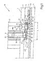
- Fig. 1 shows a profile composite 10 with a connector 11 in an embodiment according to the first variant of the invention.
- the present profile composite 10 has a first profile 1 and a second profile 2, which are formed substantially the same.
- the first profile 1 is the through a profile web 3 formed undercut 5 shown, between which undercut 5 and the groove bottom 9 a groove 7 extends, which has a bottleneck between two opposing profile webs not shown in detail 3 and widens towards the groove bottom 9.
- the respective axes of symmetry of the profiles 1 and 2 are designated.
- the connector 11 has a connector body 13 which extends substantially flat along a connector body plane 15 indicated by dashed lines.
- the maximum thickness D of the connector body 13 is not more than 20% of a longitudinal extent L of the connector body 13.
- fixing screw 17 and anchor bolt 19 provides that, as in Fig. 1 illustrated, the anchor bolt 19 is provided for arrangement in the first opening 21 of the connector 11 and exactly one fastening screw 17 is provided for arrangement in the second opening 23 of the connector 11.
- the fastening screw 17 has a shaft 27 carrying an external thread 25 at one end and a flange 29 which extends radially outward from a screw head 31, in the present case in the form of an INBUS plug-in cup 33.
- other Einstecknäpfe be realized, for example, a hexalobular Einstecknapf.
- the anchor bolt 19 is screwed in a direction along the axis 6 extending central receiving opening 35 of the second profile 2. It is with its countersunk head 37, which in turn has an INBUS-cup 39, in the exact second opening 21 of the connector body 13 form-fitting manner held without thread. In contrast, exactly the second opening 23 carries an internal thread 41 into which the external thread 25 of the shaft 27 of the fastening screw 17 engages.
- the connector body 13 is reinforced in the region of the first opening 21 and in the region of the second opening 23 by each assuming a slightly greater thickness over a significant area. In the present case, this is realized in particular in that the second opening 23 has a threaded collar 43 facing the groove base 9 in this case.
- the first opening 21 is reinforced in its the undercut 5 facing side 45 by a paragraph-like thickening.
- a collar may also be formed on the first opening 21 on the connector body 13.
- one or more, in particular along an elongated extension extending, stiffening ribs and / or one or more, in particular along an elongated extension extending, in particular lateral webs may be provided.
- such webs can be formed in a stamped and / or bent part in the form of a sheet metal - as in the present connector body 13 - as bent-up webs.
- one or more beads or elongated nubs can be pressed in the connector body 13.
- the thread axis 47 in the second opening 23 can also run obliquely against a perpendicular to the connector body plane 15. This increases handling convenience when tightening the fastening screw 17, since an Allen key bar can be more easily inserted into the INBUS key 33 in the INBUS key pin.
- An inclined threaded axis for the fastening screw 17 would also advantageously increase the fixing region of the fastening screw 17 in the groove of the vertical profile 2. In addition, such a tilting connector would be universally usable.
- the fixing screw can be rotated in the normal direction of rotation.
- the internal thread 41 of the connector body 13 is for this purpose designed as a left-hand thread with the external thread 25 of the shaft 27.
- the threads 41, 25 are designed as fine threads with a pitch of 0.75 mm per thread, instead of normally with a pitch of 1.25 mm per thread.
- the fastening screw 17 can be tightened very smoothly, wherein according to the arrow 49 in Fig.
- the connector body 11 is pressed with its tilting edge 51 opposite side 53 of the undercut 5 away from the groove interior 9.
- tilting 49 creates a train on the anchor bolt 19, which - due to their definition in the receiving opening 35 of the vertically upstanding second profile 2 - the second profile 2 to the attracted by the profile web 3 formed surface of the first profile 1 and determines there.
- tilting is a particularly easy to produce, yet a secure profile composite 10 ensuring part of a Fig. 1A and Fig. 1B shown connection system.
- Fig. 2 shows a further preferred embodiment of a connector system in a composite profile 20 in comparison to Fig. 1
- the connector system herein has a connector 61 having exactly two second openings 59A, 59B provided with internal threads 57A, 57B. In each of these engages a fastening screw 17, as already described in relation to Fig. 1 has been described. Accordingly, the same reference numerals are given.
- the first opening 63 is arranged centrally between the second openings 59A, 59B and again takes one already with respect to FIG Fig. 1 described anchor bolt 19 on - for the anchor bolt 19 again the same reference numerals.
- the connector body 65 of the connector 61 in the region of the first opening 63 an anti-rotation - present in the form of the opening boundary of the first opening 63 forming angular survey, via which the connector 61 are fixed in the facing end sides of the profile webs 3 at the Nuttaille can.
- the anchor bolt 19 When tightening the two fastening screws 17, the anchor bolt 19 is loaded on both sides by the connector 61 as a tension connector with train. The anchor bolt 19 is pulled into the groove 7 and thereby the vertically upstanding second profile 2 is fixed to the first profile 1.
- FIG. 12 shows another embodiment of a connector system 72 in which the fastening screw 18 acts as a lever screw and the connector 61 acts as a tilting connector with a tilting edge 51 'beyond the first opening 21' - much as in FIG Fig. 1 shown. Accordingly, like reference numerals have been given for corresponding parts of the figure.
- the connector 71 of Fig. 3A, Fig. 3B provided with a first opening 21 ', which is formed in the form of a slot extending in the longitudinal direction of the connector body 73 through fork-like arms 75 of the connector body 73.
- the fork-like arms 75 have a widening 77 which runs transversely to the longitudinal direction of the connector body and serves to extend a tilting edge 51 'and thus to improve the tilting behavior of the connector 71.
- the widening 77 may optionally also be designed so that it counteracts a spreading of the fork-like arms 75 in that it rests on the outside on a groove inside.
- the fastening screw 18 provided for this purpose in turn has a flange 28 which, however, in the present case has two opposite interruptions 26 along its circumference, wherein in the region of this interruption the screw head has the dimension of the INBUS plug-in cup.
- the flange 28 in the present case has an inclined ramp 24.
- the ramp 24 may be provided on its upper side with a structure, for example with a corrugation or with ratchet teeth, which counteracts a loosening of the screw.
- the slope of the ramp 24 is such that a quarter turn of the fastening screw 18, a profile composite is closed, so that it is in the present case a ramp 24 with a quarter turn pitch.
- a ramp to have at its upper end acting as a stop additional increase.
- a ramped fixing screw such as the fastening screw 18 or a modification thereof, e.g. modified with respect to the interruptions 26 or the slope of the ramp 24 in all the aforementioned embodiments of a connector 11, 61, 71 are used.
- the connector 71 according to Fig. 3A, Fig. 3B can be particularly easy to use to subsequently connect a second profile 2 - that is, between two existing vertically upstanding profiles - to a first profile 1.
- This is the second profile 2 with a Anchor bolt 19 placed on the first profile 1, so that the anchor bolt projects into the groove 7 of the first profile 1.
- the connector 71 is inserted laterally into the groove and with its fork-like arms in the waist and the anchor bolt 19 between the countersunk screw head 37 and the thread M8 encompassing.
- the connector system can be as already based on Fig. 1 .
- the connector body 13, 65, 75 extends in Substantially flat along a connector body plane 15.
- the largest, in particular over a significant range assumed thickness D of the connector body 13, 65, 75 is not more than 20% of a longitudinal extent L of the connector body 13, 65, 75.
- the connector body 13, 65, 75 can be formed in the form of a sheet metal part and / or a stamped and / or bent part.
- An attachment screw 17, 18 provided for forming a connector system has at one end a shaft 27 carrying an external thread 25.
- a flange 29 is formed, which extends from a screw head 31 radially outward. The flange 29 is supported when turning the fastening screw 17, 18 in the internal thread 41 of the connector 11, 61, 71 against the profile web third of the first profile 1 from.
- the connector system 11, 61, 71 also provides an anchor bolt 19 according to the concept of the invention.
- the connector 11 is formed as a tilting connector, wherein the first opening is formed in the form of a unthreaded screw hole.
- the connector 71 is formed as a tilting connector, wherein the first opening 21 is formed in the form of a slot of the connector body 73 which extends in the longitudinal direction of the connector body and is bounded by fork-like arms 75.
- the connector 61 is formed as a tension connector.
Landscapes
- Engineering & Computer Science (AREA)
- General Engineering & Computer Science (AREA)
- Mechanical Engineering (AREA)
- Dowels (AREA)
- Details Of Connecting Devices For Male And Female Coupling (AREA)
- Connector Housings Or Holding Contact Members (AREA)
- Coupling Device And Connection With Printed Circuit (AREA)
Claims (15)
- Système de raccord (12, 72) comprenant un connecteur (11, 61, 71) d'une vis de fixation (17, 18) et une vis d'ancrage (19), le connecteur (11, 61, 71) étant conçu pour être fixé dans une rainure (7) d'un premier profilé (1) pourvue d'une contre-dépouille (5) formée par une nervure profilée (3), et ayant un corps de connecteur (13, 65, 75), qui présente : une première ouverture (21, 63, 31') pour une vis d'ancrage (19), une deuxième ouverture (23, 23', 59A, 59B) pourvue d'un filetage interne (41) pour la vis de fixation (17, 18), la vis d'ancrage (19) étant prévue pour être disposée dans la première ouverture (21, 21', 63) du connecteur (11, 61, 71) et la vis de fixation (17, 18) étant prévue pour être disposée dans la deuxième ouverture (23, 59A, 59B), le corps de connecteur (13) présentant exactement une deuxième ouverture (23) pourvue d'un filetage interne (41, 57A, 57B) pour la vis de fixation (17) et exactement une vis de fixation (17, 18) étant prévue pour être disposée dans l'exactement une deuxième ouverture (23'), la vis de fixation (17, 18) étant prévue pour servir de vis de levier, caractérisé en ce que le corps de connecteur (13, 65, 75) s'étend essentiellement à plat le long d'un plan de corps de connecteur (15), et la vis de fixation (17, 18) présente à une extrémité une tige (27) portant un filetage extérieur (25) et une bride façonnée (28, 29), qui s'étend depuis une tête de vis (31) radialement vers l'extérieur, et le connecteur (11, 71) étant prévu pour agir en tant que connecteur basculant avec une arête de basculement (51, 51') au-delà de la première ouverture (21, 21').
- Système de connecteur (12, 72) selon la revendication 1, caractérisé en ce que la plus grande épaisseur (D), adoptée notamment sur une plage considérable, du corps de connecteur (13, 65), ne vaut pas plus de 20% d'une étendue longitudinale du corps de connecteur (13, 65).
- Système de connecteur (12, 72) selon la revendication 1 ou 2, caractérisé en ce que le corps de connecteur (13, 65) est renforcé au moins dans la région de la première ouverture (21, 63).
- Système de connecteur (12, 72) selon l'une quelconque des revendications 1 à 3, caractérisé en ce que le renforcement est formé en forme d'une augmentation de l'épaisseur (D) du corps de connecteur (13, 65) et/ou le corps de connecteur (13, 65) présente une ou plusieurs ailettes de renforcement s'étendant notamment le long d'une étendue longitudinale, et/ou le corps de connecteur (13, 65) présente une ou plusieurs nervures s'étendant notamment le long d'une étendue longitudinale, notamment latérales.
- Système de connecteur (12, 72) selon l'une quelconque des revendications 1 à 4, caractérisé en ce que le corps de connecteur (13, 65) est formé sous forme de pièce en tôle et/ou de pièce estampée et/ou cintrée.
- Système de connecteur (12, 72) selon l'une quelconque des revendications 1 à 5, caractérisé en ce que la deuxième ouverture (23, 59A, 59B) présente un col fileté (43) pouvant être tourné vers la nervure profilée.
- Système de connecteur (12, 72) selon l'une quelconque des revendications 1 à 6, caractérisé en ce qu'un axe fileté (47) dans la deuxième ouverture (23, 59a, 59b) s'étend obliquement vers une perpendiculaire au plan du corps de connecteur (15).
- Système de connecteur (12, 72) selon l'une quelconque des revendications 1 à 7, caractérisé en ce que le filetage interne (41, 57A, 57B) est un filetage à gauche.
- Système de connecteur (12, 72) selon l'une quelconque des revendications 1 à 8, caractérisé en ce que le filetage interne (41, 57A, 57B) est un filetage fin.
- Système de connecteur (12, 72) selon l'une quelconque des revendications 1 à 9, caractérisé en ce que le corps de connecteur (13, 65) présente, dans la région de la première ouverture (21, 63), un moyen pour solidariser en rotation le corps de connecteur (13, 65).
- Système de connecteur (12, 72) selon l'une quelconque des revendications 1 à 10, caractérisé en ce qu'une bordure d'ouverture formée sous forme de rehaussement polygonal est prévue pour la fixation solidaire en rotation du corps de connecteur (13, 65) sur la nervure profilée (3).
- Système de connecteur (12, 72) selon l'une quelconque des revendications 1 à 11, caractérisé en ce que la première ouverture (21, 63) est formée en forme de trou de vis sans filetage.
- Système de connecteur (12, 72) selon l'une quelconque des revendications 1 à 12, caractérisé en ce que la deuxième ouverture (21') est formée en forme de fente du corps de connecteur (73) s'étendant dans la direction longitudinale du corps de connecteur (73) et bordée par des bras de type fourche (73).
- Système de connecteur (12, 72) selon l'une quelconque des revendications 1 à 13, caractérisé en ce qu'un bras de type fourche (75) présente un élargissement (51') à l'extrémité, s'étendant transversalement à la direction longitudinale du corps de connecteur (73).
- Assemblage profilé comprenant un premier profilé (1) avec une rainure (7) pourvue d'une contre-dépouille formée par une nervure profilée (3) et un deuxième profilé (2) avec une ouverture de réception et un système de raccord (12, 72) selon l'une quelconque des revendications 1 à 14.
Applications Claiming Priority (2)
| Application Number | Priority Date | Filing Date | Title |
|---|---|---|---|
| DE202007000370U DE202007000370U1 (de) | 2007-01-10 | 2007-01-10 | Zug/Kippverbindersystem |
| PCT/EP2007/011340 WO2008083832A1 (fr) | 2007-01-10 | 2007-12-21 | Système de raccord à traction/à bascule |
Publications (2)
| Publication Number | Publication Date |
|---|---|
| EP2126378A1 EP2126378A1 (fr) | 2009-12-02 |
| EP2126378B1 true EP2126378B1 (fr) | 2011-06-15 |
Family
ID=37950402
Family Applications (1)
| Application Number | Title | Priority Date | Filing Date |
|---|---|---|---|
| EP07857055A Not-in-force EP2126378B1 (fr) | 2007-01-10 | 2007-12-21 | Système de raccord à traction/à bascule |
Country Status (6)
| Country | Link |
|---|---|
| US (1) | US8444342B2 (fr) |
| EP (1) | EP2126378B1 (fr) |
| AT (1) | ATE513140T1 (fr) |
| CA (1) | CA2674687C (fr) |
| DE (1) | DE202007000370U1 (fr) |
| WO (1) | WO2008083832A1 (fr) |
Families Citing this family (4)
| Publication number | Priority date | Publication date | Assignee | Title |
|---|---|---|---|---|
| DE202014102037U1 (de) * | 2014-04-30 | 2015-07-31 | Hartmut Flaig | Profilverbinder sowie Profilverbund |
| DE102016111711A1 (de) * | 2016-06-27 | 2017-12-28 | Abb Schweiz Ag | Installationsschaltgerät mit einem Gehäuse und mit einer Schraubanschlussklemme |
| PL3628875T3 (pl) * | 2018-09-28 | 2023-02-27 | Uponor Innovation Ab | Przesuwny blok montażowy do wkładania w szynę, układ mocujący do instalacji technicznej oraz ich zastosowanie |
| US11624394B2 (en) * | 2020-10-22 | 2023-04-11 | D Three Enterprises, Llc | Channel strut fasteners |
Family Cites Families (17)
| Publication number | Priority date | Publication date | Assignee | Title |
|---|---|---|---|---|
| DE3829306A1 (de) | 1988-08-30 | 1990-03-08 | Rolf Prettl | Konstruktionselement |
| DE9006344U1 (de) * | 1990-06-05 | 1990-09-06 | Bahr, Frank, 4952 Porta Westfalica | Vorrichtung zum lösbaren Verbinden von zwei Profilstäben |
| DE9013802U1 (de) | 1990-10-04 | 1990-12-06 | RK Rose + Krieger GmbH & Co. KG Verbindungs- und Positioniersysteme, 4952 Porta Westfalica | Vorrichtung zum lösbaren Verbinden zweier Profilstäbe |
| DE4127284C1 (en) | 1991-08-17 | 1992-12-10 | Minitec Linear-Antriebselemente Und Montage-Systeme Gmbh, 6797 Waldmohr, De | Profile structure bar for connectors - has bars with grooves and end-threaded bores into which holder is fixed which then engages into groove of next bar |
| DE4244396C2 (de) | 1992-12-29 | 1998-04-30 | Heron Sondermaschinen Und Steu | Verbindungsstück für die lösbare Verbindung zweier Profilstäbe, vorzugsweise aus Leichtmetall |
| DE9313596U1 (de) | 1993-09-09 | 1993-10-21 | RK Rose + Krieger GmbH & Co. KG, 32457 Porta Westfalica | Zwei, durch eine Verbindungseinrichtung lösbar miteinander verbundene Profilstäbe |
| DE9414884U1 (de) | 1994-06-03 | 1994-11-10 | Bonanno, Antonio, 61440 Oberursel | Verbindungselement |
| US5722948A (en) * | 1996-02-14 | 1998-03-03 | Gross; Fredric J. | Covering for an ocular device |
| DE19825426B4 (de) | 1997-07-10 | 2006-03-16 | Werner Turck Gmbh & Co. Kg | In eine T-Nut einsetzbarer Näherungsschalter bzw. Befestigungselement dafür |
| US6582149B1 (en) * | 1998-12-15 | 2003-06-24 | Winfried K. W. Holscher | Coupling device for connecting a first workpiece to a second one |
| DE19925993B4 (de) * | 1999-06-08 | 2010-07-01 | Werner Turck Gmbh & Co. Kg | In eine T-Nut einsetzbarer Näherungsschalter |
| EP1061272B1 (fr) * | 1999-06-17 | 2003-03-19 | Zihlmann Engineering | Liaison transversale pour des barres profilées |
| DE20203283U1 (de) | 2002-02-28 | 2002-05-23 | RK Rose + Krieger GmbH & Co. KG Verbindungs- und Positioniersysteme, 32423 Minden | Klemmverbinder |
| DE20210133U1 (de) | 2002-07-01 | 2003-11-13 | Bosch Rexroth AG, 70173 Stuttgart | Verbindung von Profilstreben |
| EP1706652B1 (fr) | 2004-01-22 | 2008-03-26 | Winfried K. W. Holscher | Ensemble d'assemblage de deux profiles creux continus |
| DE202005013097U1 (de) * | 2005-08-17 | 2005-12-22 | Stauss, Ulrich | Kippverbinder |
| US8100600B2 (en) * | 2008-10-23 | 2012-01-24 | Robert Bosch Gmbh | Pivoting connector assembly for connecting two members |
-
2007
- 2007-01-10 DE DE202007000370U patent/DE202007000370U1/de not_active Expired - Lifetime
- 2007-12-21 US US12/522,842 patent/US8444342B2/en not_active Expired - Fee Related
- 2007-12-21 AT AT07857055T patent/ATE513140T1/de active
- 2007-12-21 WO PCT/EP2007/011340 patent/WO2008083832A1/fr not_active Ceased
- 2007-12-21 EP EP07857055A patent/EP2126378B1/fr not_active Not-in-force
- 2007-12-21 CA CA2674687A patent/CA2674687C/fr not_active Expired - Fee Related
Also Published As
| Publication number | Publication date |
|---|---|
| DE202007000370U1 (de) | 2007-04-05 |
| CA2674687A1 (fr) | 2008-07-17 |
| US8444342B2 (en) | 2013-05-21 |
| EP2126378A1 (fr) | 2009-12-02 |
| US20100003073A1 (en) | 2010-01-07 |
| ATE513140T1 (de) | 2011-07-15 |
| CA2674687C (fr) | 2014-09-30 |
| WO2008083832A1 (fr) | 2008-07-17 |
Similar Documents
| Publication | Publication Date | Title |
|---|---|---|
| DE4401746C2 (de) | T Mutter | |
| DE102008028108A1 (de) | Vorrichtung zum Verbinden einer Profilschiene mit einem anderen Bauteil | |
| EP2341254A2 (fr) | Elément de connecteur et connecteur croisé | |
| EP3649353A1 (fr) | Système de fixation | |
| EP1899613B1 (fr) | Vis d'ancrage | |
| DE112007002638B4 (de) | Verbesserungen an Befestigungsmitteln | |
| EP2126378B1 (fr) | Système de raccord à traction/à bascule | |
| EP2309137A1 (fr) | Cheville d'un dispositif d'assemblage | |
| DE102009020285B4 (de) | Knochenplatte zum Fixieren von Knochenteilen bei operativen Korrekturen der Hallux Valgus Deformität | |
| DE19946890C2 (de) | Halteelement zur unverlierbaren Halterung von Kopfschrauben | |
| DE10200964A1 (de) | System zum Verbinden zweier Profilstäbe | |
| DE202011003315U1 (de) | Verbindungsvorrichtung | |
| EP3211146B1 (fr) | Systeme de liaison pour une construction en bois | |
| EP2458229B1 (fr) | Dispositif de connexion | |
| DE102014018920B4 (de) | Verbindereinrichtung für Profilstäbe | |
| DE3441562A1 (de) | Rohrschelle | |
| AT516526B1 (de) | Anordnung und Befestigungselement | |
| WO2008028607A2 (fr) | Cheville | |
| DE102018105970A1 (de) | Variable Deckenbefestigung | |
| WO2008151716A2 (fr) | Système de meuble et meuble | |
| DE4013690A1 (de) | Rohrbefestigungsschelle mit einem verankerungsbolzen und zwei bogenfoermigen schellenteilen | |
| EP4481298A1 (fr) | Pince modulaire pour fixer au moins un module solaire | |
| DE202026100856U1 (de) | Dachhaken sowie Anordnung aus Dachhaken und Fixierelement | |
| EP3093508B1 (fr) | Benne basculante et procédé de fixation d'une benne basculante | |
| AT410167B (de) | Beschlag zur lösbaren befestigung |
Legal Events
| Date | Code | Title | Description |
|---|---|---|---|
| PUAI | Public reference made under article 153(3) epc to a published international application that has entered the european phase |
Free format text: ORIGINAL CODE: 0009012 |
|
| 17P | Request for examination filed |
Effective date: 20090724 |
|
| AK | Designated contracting states |
Kind code of ref document: A1 Designated state(s): AT BE BG CH CY CZ DE DK EE ES FI FR GB GR HU IE IS IT LI LT LU LV MC MT NL PL PT RO SE SI SK TR |
|
| DAX | Request for extension of the european patent (deleted) | ||
| GRAP | Despatch of communication of intention to grant a patent |
Free format text: ORIGINAL CODE: EPIDOSNIGR1 |
|
| GRAS | Grant fee paid |
Free format text: ORIGINAL CODE: EPIDOSNIGR3 |
|
| GRAA | (expected) grant |
Free format text: ORIGINAL CODE: 0009210 |
|
| AK | Designated contracting states |
Kind code of ref document: B1 Designated state(s): AT BE BG CH CY CZ DE DK EE ES FI FR GB GR HU IE IS IT LI LT LU LV MC MT NL PL PT RO SE SI SK TR |
|
| REG | Reference to a national code |
Ref country code: GB Ref legal event code: FG4D Free format text: NOT ENGLISH Ref country code: CH Ref legal event code: EP |
|
| REG | Reference to a national code |
Ref country code: IE Ref legal event code: FG4D Free format text: LANGUAGE OF EP DOCUMENT: GERMAN |
|
| REG | Reference to a national code |
Ref country code: DE Ref legal event code: R096 Ref document number: 502007007474 Country of ref document: DE Effective date: 20110721 |
|
| REG | Reference to a national code |
Ref country code: NL Ref legal event code: T3 |
|
| PG25 | Lapsed in a contracting state [announced via postgrant information from national office to epo] |
Ref country code: SE Free format text: LAPSE BECAUSE OF FAILURE TO SUBMIT A TRANSLATION OF THE DESCRIPTION OR TO PAY THE FEE WITHIN THE PRESCRIBED TIME-LIMIT Effective date: 20110615 Ref country code: LT Free format text: LAPSE BECAUSE OF FAILURE TO SUBMIT A TRANSLATION OF THE DESCRIPTION OR TO PAY THE FEE WITHIN THE PRESCRIBED TIME-LIMIT Effective date: 20110615 |
|
| PG25 | Lapsed in a contracting state [announced via postgrant information from national office to epo] |
Ref country code: CY Free format text: LAPSE BECAUSE OF FAILURE TO SUBMIT A TRANSLATION OF THE DESCRIPTION OR TO PAY THE FEE WITHIN THE PRESCRIBED TIME-LIMIT Effective date: 20110615 Ref country code: FI Free format text: LAPSE BECAUSE OF FAILURE TO SUBMIT A TRANSLATION OF THE DESCRIPTION OR TO PAY THE FEE WITHIN THE PRESCRIBED TIME-LIMIT Effective date: 20110615 Ref country code: GR Free format text: LAPSE BECAUSE OF FAILURE TO SUBMIT A TRANSLATION OF THE DESCRIPTION OR TO PAY THE FEE WITHIN THE PRESCRIBED TIME-LIMIT Effective date: 20110916 Ref country code: LV Free format text: LAPSE BECAUSE OF FAILURE TO SUBMIT A TRANSLATION OF THE DESCRIPTION OR TO PAY THE FEE WITHIN THE PRESCRIBED TIME-LIMIT Effective date: 20110615 Ref country code: SI Free format text: LAPSE BECAUSE OF FAILURE TO SUBMIT A TRANSLATION OF THE DESCRIPTION OR TO PAY THE FEE WITHIN THE PRESCRIBED TIME-LIMIT Effective date: 20110615 |
|
| REG | Reference to a national code |
Ref country code: IE Ref legal event code: FD4D |
|
| PG25 | Lapsed in a contracting state [announced via postgrant information from national office to epo] |
Ref country code: IE Free format text: LAPSE BECAUSE OF FAILURE TO SUBMIT A TRANSLATION OF THE DESCRIPTION OR TO PAY THE FEE WITHIN THE PRESCRIBED TIME-LIMIT Effective date: 20110615 Ref country code: PT Free format text: LAPSE BECAUSE OF FAILURE TO SUBMIT A TRANSLATION OF THE DESCRIPTION OR TO PAY THE FEE WITHIN THE PRESCRIBED TIME-LIMIT Effective date: 20111017 Ref country code: EE Free format text: LAPSE BECAUSE OF FAILURE TO SUBMIT A TRANSLATION OF THE DESCRIPTION OR TO PAY THE FEE WITHIN THE PRESCRIBED TIME-LIMIT Effective date: 20110615 Ref country code: IS Free format text: LAPSE BECAUSE OF FAILURE TO SUBMIT A TRANSLATION OF THE DESCRIPTION OR TO PAY THE FEE WITHIN THE PRESCRIBED TIME-LIMIT Effective date: 20111015 Ref country code: CZ Free format text: LAPSE BECAUSE OF FAILURE TO SUBMIT A TRANSLATION OF THE DESCRIPTION OR TO PAY THE FEE WITHIN THE PRESCRIBED TIME-LIMIT Effective date: 20110615 |
|
| PG25 | Lapsed in a contracting state [announced via postgrant information from national office to epo] |
Ref country code: RO Free format text: LAPSE BECAUSE OF FAILURE TO SUBMIT A TRANSLATION OF THE DESCRIPTION OR TO PAY THE FEE WITHIN THE PRESCRIBED TIME-LIMIT Effective date: 20110615 Ref country code: SK Free format text: LAPSE BECAUSE OF FAILURE TO SUBMIT A TRANSLATION OF THE DESCRIPTION OR TO PAY THE FEE WITHIN THE PRESCRIBED TIME-LIMIT Effective date: 20110615 Ref country code: PL Free format text: LAPSE BECAUSE OF FAILURE TO SUBMIT A TRANSLATION OF THE DESCRIPTION OR TO PAY THE FEE WITHIN THE PRESCRIBED TIME-LIMIT Effective date: 20110615 |
|
| PLBE | No opposition filed within time limit |
Free format text: ORIGINAL CODE: 0009261 |
|
| STAA | Information on the status of an ep patent application or granted ep patent |
Free format text: STATUS: NO OPPOSITION FILED WITHIN TIME LIMIT |
|
| 26N | No opposition filed |
Effective date: 20120316 |
|
| PG25 | Lapsed in a contracting state [announced via postgrant information from national office to epo] |
Ref country code: DK Free format text: LAPSE BECAUSE OF FAILURE TO SUBMIT A TRANSLATION OF THE DESCRIPTION OR TO PAY THE FEE WITHIN THE PRESCRIBED TIME-LIMIT Effective date: 20110615 |
|
| BERE | Be: lapsed |
Owner name: STAUSS, ULRICH Effective date: 20111231 |
|
| REG | Reference to a national code |
Ref country code: DE Ref legal event code: R097 Ref document number: 502007007474 Country of ref document: DE Effective date: 20120316 |
|
| PG25 | Lapsed in a contracting state [announced via postgrant information from national office to epo] |
Ref country code: MC Free format text: LAPSE BECAUSE OF NON-PAYMENT OF DUE FEES Effective date: 20111231 |
|
| REG | Reference to a national code |
Ref country code: CH Ref legal event code: PL |
|
| PG25 | Lapsed in a contracting state [announced via postgrant information from national office to epo] |
Ref country code: CH Free format text: LAPSE BECAUSE OF NON-PAYMENT OF DUE FEES Effective date: 20111231 Ref country code: LI Free format text: LAPSE BECAUSE OF NON-PAYMENT OF DUE FEES Effective date: 20111231 Ref country code: BE Free format text: LAPSE BECAUSE OF NON-PAYMENT OF DUE FEES Effective date: 20111231 |
|
| PG25 | Lapsed in a contracting state [announced via postgrant information from national office to epo] |
Ref country code: MT Free format text: LAPSE BECAUSE OF FAILURE TO SUBMIT A TRANSLATION OF THE DESCRIPTION OR TO PAY THE FEE WITHIN THE PRESCRIBED TIME-LIMIT Effective date: 20110615 |
|
| PG25 | Lapsed in a contracting state [announced via postgrant information from national office to epo] |
Ref country code: ES Free format text: LAPSE BECAUSE OF FAILURE TO SUBMIT A TRANSLATION OF THE DESCRIPTION OR TO PAY THE FEE WITHIN THE PRESCRIBED TIME-LIMIT Effective date: 20110926 |
|
| REG | Reference to a national code |
Ref country code: DE Ref legal event code: R082 Ref document number: 502007007474 Country of ref document: DE |
|
| PG25 | Lapsed in a contracting state [announced via postgrant information from national office to epo] |
Ref country code: LU Free format text: LAPSE BECAUSE OF NON-PAYMENT OF DUE FEES Effective date: 20111221 |
|
| PG25 | Lapsed in a contracting state [announced via postgrant information from national office to epo] |
Ref country code: BG Free format text: LAPSE BECAUSE OF FAILURE TO SUBMIT A TRANSLATION OF THE DESCRIPTION OR TO PAY THE FEE WITHIN THE PRESCRIBED TIME-LIMIT Effective date: 20110915 |
|
| PG25 | Lapsed in a contracting state [announced via postgrant information from national office to epo] |
Ref country code: TR Free format text: LAPSE BECAUSE OF FAILURE TO SUBMIT A TRANSLATION OF THE DESCRIPTION OR TO PAY THE FEE WITHIN THE PRESCRIBED TIME-LIMIT Effective date: 20110615 |
|
| PG25 | Lapsed in a contracting state [announced via postgrant information from national office to epo] |
Ref country code: HU Free format text: LAPSE BECAUSE OF FAILURE TO SUBMIT A TRANSLATION OF THE DESCRIPTION OR TO PAY THE FEE WITHIN THE PRESCRIBED TIME-LIMIT Effective date: 20110615 |
|
| PGFP | Annual fee paid to national office [announced via postgrant information from national office to epo] |
Ref country code: FR Payment date: 20141208 Year of fee payment: 8 |
|
| PGFP | Annual fee paid to national office [announced via postgrant information from national office to epo] |
Ref country code: NL Payment date: 20151106 Year of fee payment: 9 Ref country code: AT Payment date: 20151109 Year of fee payment: 9 |
|
| REG | Reference to a national code |
Ref country code: FR Ref legal event code: ST Effective date: 20160831 |
|
| PG25 | Lapsed in a contracting state [announced via postgrant information from national office to epo] |
Ref country code: FR Free format text: LAPSE BECAUSE OF NON-PAYMENT OF DUE FEES Effective date: 20151231 |
|
| PGFP | Annual fee paid to national office [announced via postgrant information from national office to epo] |
Ref country code: DE Payment date: 20161114 Year of fee payment: 10 Ref country code: GB Payment date: 20161117 Year of fee payment: 10 |
|
| PGFP | Annual fee paid to national office [announced via postgrant information from national office to epo] |
Ref country code: IT Payment date: 20161223 Year of fee payment: 10 |
|
| REG | Reference to a national code |
Ref country code: NL Ref legal event code: MM Effective date: 20170101 |
|
| REG | Reference to a national code |
Ref country code: AT Ref legal event code: MM01 Ref document number: 513140 Country of ref document: AT Kind code of ref document: T Effective date: 20161221 |
|
| PG25 | Lapsed in a contracting state [announced via postgrant information from national office to epo] |
Ref country code: NL Free format text: LAPSE BECAUSE OF NON-PAYMENT OF DUE FEES Effective date: 20170101 |
|
| PG25 | Lapsed in a contracting state [announced via postgrant information from national office to epo] |
Ref country code: AT Free format text: LAPSE BECAUSE OF NON-PAYMENT OF DUE FEES Effective date: 20161221 |
|
| REG | Reference to a national code |
Ref country code: DE Ref legal event code: R119 Ref document number: 502007007474 Country of ref document: DE |
|
| GBPC | Gb: european patent ceased through non-payment of renewal fee |
Effective date: 20171221 |
|
| PG25 | Lapsed in a contracting state [announced via postgrant information from national office to epo] |
Ref country code: DE Free format text: LAPSE BECAUSE OF NON-PAYMENT OF DUE FEES Effective date: 20180703 Ref country code: IT Free format text: LAPSE BECAUSE OF NON-PAYMENT OF DUE FEES Effective date: 20171221 |
|
| PG25 | Lapsed in a contracting state [announced via postgrant information from national office to epo] |
Ref country code: GB Free format text: LAPSE BECAUSE OF NON-PAYMENT OF DUE FEES Effective date: 20171221 |