EP2126510B1 - Procédé et dispositif de détermination sans contact d'un décalage latéral par rapport à une direction rectiligne - Google Patents
Procédé et dispositif de détermination sans contact d'un décalage latéral par rapport à une direction rectiligne Download PDFInfo
- Publication number
- EP2126510B1 EP2126510B1 EP08715496.9A EP08715496A EP2126510B1 EP 2126510 B1 EP2126510 B1 EP 2126510B1 EP 08715496 A EP08715496 A EP 08715496A EP 2126510 B1 EP2126510 B1 EP 2126510B1
- Authority
- EP
- European Patent Office
- Prior art keywords
- sensor elements
- surface structure
- sensor
- photodiode
- straight direction
- Prior art date
- Legal status (The legal status is an assumption and is not a legal conclusion. Google has not performed a legal analysis and makes no representation as to the accuracy of the status listed.)
- Not-in-force
Links
- 238000000034 method Methods 0.000 title claims description 20
- 230000002596 correlated effect Effects 0.000 claims description 9
- 238000003384 imaging method Methods 0.000 claims description 9
- 230000000875 corresponding effect Effects 0.000 claims description 2
- 238000005286 illumination Methods 0.000 claims description 2
- 230000003287 optical effect Effects 0.000 claims 4
- 238000003491 array Methods 0.000 claims 2
- 230000002123 temporal effect Effects 0.000 claims 1
- 238000005259 measurement Methods 0.000 description 4
- 238000004364 calculation method Methods 0.000 description 2
- 230000001419 dependent effect Effects 0.000 description 2
- 238000011161 development Methods 0.000 description 2
- 238000013507 mapping Methods 0.000 description 2
- 238000006073 displacement reaction Methods 0.000 description 1
- 230000000694 effects Effects 0.000 description 1
- 238000005516 engineering process Methods 0.000 description 1
- 238000009499 grossing Methods 0.000 description 1
- 238000004519 manufacturing process Methods 0.000 description 1
- 238000012986 modification Methods 0.000 description 1
- 230000004048 modification Effects 0.000 description 1
Images

Classifications
-
- G—PHYSICS
- G01—MEASURING; TESTING
- G01B—MEASURING LENGTH, THICKNESS OR SIMILAR LINEAR DIMENSIONS; MEASURING ANGLES; MEASURING AREAS; MEASURING IRREGULARITIES OF SURFACES OR CONTOURS
- G01B11/00—Measuring arrangements characterised by the use of optical techniques
- G01B11/002—Measuring arrangements characterised by the use of optical techniques for measuring two or more coordinates
-
- G—PHYSICS
- G01—MEASURING; TESTING
- G01B—MEASURING LENGTH, THICKNESS OR SIMILAR LINEAR DIMENSIONS; MEASURING ANGLES; MEASURING AREAS; MEASURING IRREGULARITIES OF SURFACES OR CONTOURS
- G01B11/00—Measuring arrangements characterised by the use of optical techniques
- G01B11/26—Measuring arrangements characterised by the use of optical techniques for measuring angles or tapers; for testing the alignment of axes
- G01B11/275—Measuring arrangements characterised by the use of optical techniques for measuring angles or tapers; for testing the alignment of axes for testing wheel alignment
- G01B11/2755—Measuring arrangements characterised by the use of optical techniques for measuring angles or tapers; for testing the alignment of axes for testing wheel alignment using photoelectric detection means
Definitions
- the present invention relates to a method and apparatus for non-contact determination of lateral offset from straight-line motion when moving an object relative to an object having a stochastic surface structure, mapping the surface structure onto a photosensitive sensor.
- a sensor is attached to an object in motion, with which measured variables relative to another object with a stochastic surface can be determined.
- an object in motion may be a vehicle whose movement relative to the roadway is determined.
- the lateral offset is to be determined as a deviation of the vehicle movement from the straight ahead. For example, as long as the vehicle is driving straight ahead and there are no disturbances on the vehicle, there is no lateral offset. It is conceivable that e.g. a lateral wind gust acting on the vehicle in straight-ahead motion laterally displaces the vehicle.
- the invention relates to a method and apparatus for determining the angle as a quantity for the deviation of the movement from the straight-line direction or the desired direction.
- the invention relates to a method and an apparatus for measuring the skew angle.
- the slip angle is an important parameter in vehicle technology and vehicle development of non-rail land vehicles. In tire development, e.g. in this way conclusions about the cornering forces and the handling of the tires of a vehicle are drawn.
- slip angle in this case is meant the angle between the direction in which a tire points and the direction in which it actually moves on the road.
- the US 2006/045314 discloses a measuring system for detecting object shifts by means of an image correlation method.
- the invention was based on the object of providing a method for the contactless determination of the lateral offset relative to a straight-line alignment when moving an object relative to an object with a stochastic surface structure, in particular for the high-resolution determination of the slip angle. Another object was to realize a device with which the lateral offset can be determined with high accuracy, even at low speeds, which is compact and lightweight, has little interference-prone components and the distance independently with constant accuracy measurement results for determining the slip angle supplies.
- the method and the device according to the invention are characterized in that the lateral offset with respect to a predetermined straight-line orientation when moving an object relative to another object with a stochastic surface structure is determined by the surface structure being based on a photosensitive sensor located in the image plane of an optic is displayed.
- the photosensitive sensor is formed from at least two same sensor elements arranged one behind the other in the straight-line direction at a defined distance from one another.
- the sensor elements have a spatially resolving longitudinal extent transversely to the straight-line direction and generate a spatial frequency signal corresponding to the surface structure, which is read out with an electronic unit.
- the spatial frequency signal of a second sensor element in the direction of movement is read out in such a time-shifted manner relative to the spatial frequency signal of the first sensor element that the same, at least partially matching surface structure is imaged on both sensor elements.
- the spatial frequency signals of the first and second sensor elements are correlated with one another in a computing unit.
- the magnitude of the lateral offset of the correlated spatial frequency signals relative to one another on the spatially resolving sensor elements is determined with the aid of the correlation coefficient generated in the arithmetic unit.
- special, e.g. Photodiode chips are used, which have a plurality of sensor elements with a spatially resolving longitudinal extension transversely to the straight-ahead direction in the direction of travel behind one another on a support.
- the distance of the individual sensor elements with high accuracy is reproducible and does not need to be elaborately determined metrologically as in the production of individual elements and optionally calibrated.
- the movement speed is additionally determined and, depending on this, the time shift between the read-out of the first and a second sensor element is determined.
- the more accurate the movement speed v in Straight alignment and thus determined perpendicular to the longitudinal extent of the sensor elements, the more accurate the optimal time shift t can be set as a function of the defined distance s a between the first and a second sensor element (t s a / v).
- a further possibility for improving the accuracy is that several of the n second sensor elements are read successively with time displacements nxt, all the second spatial frequency signals determined in this way are respectively correlated with the first spatial frequency signal, and from this an optimal correlation coefficient for determining the lateral offset is calculated on the spatially resolving sensor elements.
- the numerical value 1 is assumed to be the maximum as the ideal correlation coefficient, so that by definition an optimum correlation coefficient should come as close as possible to the numerical value of 1.
- a time range is defined for the time shift determined with the aid of the movement speed, in which a second sensor element is read a plurality of times. Subsequently, all second spatial frequency signals are respectively correlated with the first spatial frequency signal, and from this an averaged correlation coefficient is calculated. In this way, any inaccuracy in the determination of the movement speed can be compensated, and a higher accuracy can be achieved in the determination of the correlation coefficient, particularly in the range of slow relative speeds.
- the lateral offset can be determined by determining the index value i max at which the function of the correlation coefficient has a maximum (MAX [r (i)]).
- the amount of the lateral offset s b is then particularly easy to calculate from the known strip width b of the strip-shaped photoelements multiplied by the index value i max .
- An improvement in the signal quality of the spatial frequency signals generated by the photodiode rows is achieved by adjusting the exposure time of the sensor elements to the movement speed of the sensor relative to the surface structure.
- the exposure time is understood in this case as the time in which the photodiode signal is built up in the sensor element, that is, integrated.
- a shorter exposure time should be selected for fast speeds, while a longer exposure time is permitted for slow speeds.
- the time shift between the readout of the first and second sensor elements taking into account the magnification of the optics selected such that are mapped to the sensor elements in the direction of movement matching sections of the surface structure.
- the time shift is therefore as a quotient of the distance s a and the multiplied by the magnification A velocity v to form.
- Deviations are tolerable within a certain range, but the section of the surface structure imaged on the first sensor element should have shifted by at most the amount of height of a photodiode element (pixel) on one of the second photodiode elements, since otherwise the correlation can no longer be reliably performed. To this This ensures that the two determined spatial frequency signals can be correlated with each other.
- the optic is designed according to the invention for a telecentric imaging of the surface structure. In this way, a large working distance range can be realized.
- the sensor system can be adapted in particular to the geometry (distance and width of the pixels) of the strip-shaped photodiode elements and to different textures of the stochastic surface structure in order to obtain well-evaluable spatial frequency signals.
- a distance sensor is additionally provided, taking into account a changing imaging scale, eg when the telecentric working distance range is exceeded, the resulting changed magnification can be taken into account and the working distance range can be increased.
- the known distance-dependent change in the magnification can be taken into account on the basis of the measured distance.
- the use of the distance sensor on the optics for a telecentric imaging of the surface structure can be dispensed with.
- the sensor formed in this way is also able to provide almost distance-independent measurement results.
- a speed sensor for determining the relative speed in the straight-ahead direction, ie perpendicular to the longitudinal extension of the sensor elements, is additionally provided.
- non-contact speed sensors which supply the absolute magnitude of the speed of the sensor perpendicular to the longitudinal extent of the sensor elements and thus independent of the movement angle are suitable for determining the optimum time shift between the readout of the first and a second sensor element.
- the sensor element can be formed from two rows of photodiodes with strip-shaped photodiode elements (pixels) parallel to the straight-line orientation and the spatial frequency signals have a surprisingly high quality. In this way, compact and cost-producible sensors can be realized with standardized photodiode rows.
- a diode array with, for example, 512 pixels, each having a width of approximately 12 ⁇ m and a pixel height of 250 ⁇ m, is suitable for use in the sensor device described above.
- the correlability of the spatial frequency signals of the two diode rows determines the maximum ascertainable lateral offset.
- the resolution depends on the distance s a of the sensor elements from each other. The farther the rows of diodes are apart, the greater the resolution, the smaller the maximum determinable angle. By using longer rows of diodes, the maximum determinable angle can be increased.
- the maximum length of the usable diode rows is limited by the image field of the imaging optics.
- the readout frequency of the diode array must either be dynamically adaptable to the time shift or be chosen to be high enough the shortest possible time shift (maximum speed) the diode array is still completely readable.
- FIG. 1 a sensor device 1 is shown in a simplified perspective view.
- the movement in the straight-ahead direction 2 with respect to an object with a stochastic surface is shown by an arrow.
- a region of the surface structure 3 to be imaged is imaged by a lens 4, which is indicated by a lens, onto a sensor arrangement 5.
- the area of the surface structure 3 to be imaged is obliquely illuminated, by a kind Dark field illumination to improve the contrast.
- the sensor arrangement 5 comprises a first row of photodiodes 7 and a second row of photodiodes 8 at a distance a. In the longitudinal extent, the rows of photodiodes 7, 8 have n striped pixels 9.
- an electronic unit 10 For controlled reading of the photodiode rows 7, 8 an electronic unit 10 is provided.
- the electronic unit 10 likewise processes the signals of a speed sensor 11, shown schematically, and of an optionally provided distance sensor 12.
- the signals processed by the electronic unit 10 are supplied to a computing unit 16 for correlation.
- the entire sensor device 1 is arranged in a housing not shown.
- Fig. 2 shows the geometrical arrangement of the photodiode rows 7, 8 with their distance a.
- the straight line direction is represented by the arrow 2.
- a point 13 is shown, which is intended to illustrate as point 14 the lateral offset 15 of the spatial frequency signal on the second photodiode line 8.
Landscapes
- Physics & Mathematics (AREA)
- General Physics & Mathematics (AREA)
- Length Measuring Devices By Optical Means (AREA)
Claims (13)
- Une méthode pour la détermination sans contact du décalage latéral (15) relative à une direction droite (2) durant le mouvement d'un objet relative à un objet présentant une surface à structure stochastique comprenant l'imagerie de la structure de surface (3) sur un capteur photosensible (5) caractérisé en ce que:- une image de la structure de surface (3) est générée sur au moins deux éléments de capteur pareils (7, 8) positionnés l'un après l'autre à une distance définie (a) dans la direction droite (2), lesdits éléments de capteur présentant une extension longitudinale à résolution spatiale perpendiculairement à la direction droite (2) et constitués de matrices de photodiodes (7, 8) avec éléments de photodiode (9) en forme de bandes arrangés en parallèle à la direction droite (2);- un signal de fréquence spatiale correspondant à la structure de surface (3) est généré par lesdits éléments de capteur (7, 8);- le signal de fréquence spatiale d'un deuxième élément de capteur (8) dans la direction de mouvement est lu avec un retard temporel relative au signal de fréquence spatiale du premier élément de capteur (7) afin que soit créée sur les deux éléments de capteur (7, 8) une image de la même, au moins en partie identique, structure de surface (3), et- les signaux de fréquence spatiales desdits premier et deuxième éléments de capteur (7, 8) sont corrélés entre eux pour déterminer un coefficient de corrélation et dudit coefficient de corrélation est déterminé le montant du décalage latéral (15) des signaux de fréquence spatiales entre eux sur les éléments de capteur à résolution spatiale (7, 8).
- La méthode selon la revendication 1 caractérisé en ce qu'en outre la vitesse de mouvement est déterminée et, en fonction de celle-ci, le retard temporel entre la lecture du premier (7) et du deuxième (8) élément de capteur est établi.
- La méthode selon la revendication 1 ou 2 caractérisé en ce qu'après le retard temporel une pluralité de deuxièmes éléments de capteur (8) positionnés l'un après l'autre dans la direction droite (2) sont lus en séquence, chacun des deuxièmes signaux de fréquence spatiale est corrélé avec le premier signal de fréquence spatiale et un coefficient de corrélation optimum en est calculé.
- La méthode selon la revendication 1 ou 2 caractérisé en ce qu'après le retard temporel une période de temps est définie, dans ladite période de temps un deuxième élément de capteur (8) étant lu plusieurs fois, chacun des deuxièmes signaux de fréquence spatiale est corrélé avec le premier signal de fréquence spatiale et un coefficient de corrélation moyen en est calculé.
- La méthode selon l'une quelconque des revendications précédentes caractérisé en ce que les coefficients de corrélation (r(i)) sont calculés en appliquant l'équation suivante:
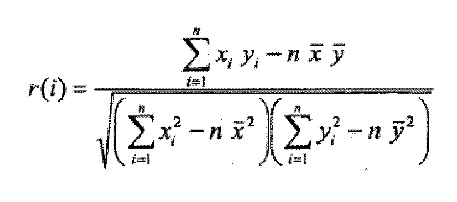
dans laqueller(i): coefficient de corrélation en fonction de i, -1 ≤ r(i) ≤ 1n: nombre de éléments de photodiodei: indice (1 ... n)xi: signal de photodiode de la première matricex : valeur moyen de tous les signaux de photodiode de la première matriceyi : signal de photodiode de la deuxième matrice ety : valeur moyen de tous les signaux de photodiode de la deuxième matrice. - La méthode selon l'une quelconque des revendications précédentes caractérisé en ce qu'un angle (α) est calculé utilisant la relation géométrique entre la distance (a) dans la direction droite (2) des éléments de capteur (7, 8) dont les lectures sont prises et le montant du décalage latéral (15).
- La méthode selon la revendication 2 caractérisé en ce que le temps d'exposition des éléments de capteur (7, 8) est ajusté à la vitesse.
- La méthode selon l'une quelconque des revendications 3 à 5 caractérisé en ce que le retard temporel entre la lecture des premier et deuxième éléments de capteur (7, 8) est choisi en tenant compte du grossissement d'image du système optique (4) par lequel la structure de surface (3) est imagée, de manière que, la partie de la structure de surface (3) dont l'image est créé sur le premier élément de capteur (7) est décalée sur un des deuxièmes éléments de capteur (8) au maximum par le montant de la hauteur d'un élément de photodiode (pixel) (9).
- Un appareil pour la détermination sans contact du décalage latéral (15) relative à une direction droite (2) durant le mouvement d'un premier objet relative à un deuxième objet présentant une surface à structure stochastique comprenant un capteur photosensible (5) pouvant être placé sur le premier objet sur lequel une image de la structure de surface (3) peut être créée caractérisé en ce que:- ledit appareil comprenant un seul système optique (4) pour imager la structure de surface (3),- dans le plan d'image du système optique (4) sont positionnés au moins deux éléments de capteur pareils (7, 8) l'un après l'autre à une distance définie (a) dans la direction droite (2), lesdits éléments de capteur présentant une extension longitudinale à résolution spatiale perpendiculairement à la direction droite (2) et constitués de matrices de photodiodes (7, 8) avec éléments de photodiode (9) en forme de bandes arrangés en parallèle à la direction droite (2);- ledit appareil en outre comprenant une unité électronique (10) pour une lecture contrôlée des signaux à résolution spatiale des éléments de capteur (7, 8) et- une unité de calcul (16) pour faire la corrélation des signaux lus des éléments de capteur (7, 8) et d'en calculer le décalage (15) des images de la structure de surface (3) sur les éléments de capteur (7, 8).
- L'appareil selon la revendication 9 caractérisé en ce que le système optique (4) est configuré pour l'imagerie télécentrique de la structure de surface (3).
- L'appareil selon la revendication 9 caractérisé en ce qu'un senseur de distance (12) est également fourni.
- L'appareil selon la revendication 10 ou 11 caractérisé en ce qu'un capteur de vitesse (11) pour déterminer la vitesse relative dans la direction droite (2) est également fourni.
- L'appareil selon l'une quelconque des revendications 9 à 12 caractérisé en ce qu'un moyen d'éclairage (6) est fourni pour l'éclairage de la structure de surface (3) à imager.
Applications Claiming Priority (2)
| Application Number | Priority Date | Filing Date | Title |
|---|---|---|---|
| DE102007008002A DE102007008002B4 (de) | 2007-02-15 | 2007-02-15 | Verfahren und Vorrichtung zum berührungslosen Bestimmen des seitlichen Versatzes gegenüber einer Geradeausrichtung |
| PCT/DE2008/000278 WO2008098568A1 (fr) | 2007-02-15 | 2008-02-15 | Procédé et dispositif de détermination sans contact d'un décalage latéral par rapport à une direction rectiligne |
Publications (2)
| Publication Number | Publication Date |
|---|---|
| EP2126510A1 EP2126510A1 (fr) | 2009-12-02 |
| EP2126510B1 true EP2126510B1 (fr) | 2014-08-20 |
Family
ID=39523540
Family Applications (1)
| Application Number | Title | Priority Date | Filing Date |
|---|---|---|---|
| EP08715496.9A Not-in-force EP2126510B1 (fr) | 2007-02-15 | 2008-02-15 | Procédé et dispositif de détermination sans contact d'un décalage latéral par rapport à une direction rectiligne |
Country Status (5)
| Country | Link |
|---|---|
| US (1) | US8064047B2 (fr) |
| EP (1) | EP2126510B1 (fr) |
| JP (1) | JP5109075B2 (fr) |
| DE (1) | DE102007008002B4 (fr) |
| WO (1) | WO2008098568A1 (fr) |
Families Citing this family (5)
| Publication number | Priority date | Publication date | Assignee | Title |
|---|---|---|---|---|
| US9677897B2 (en) | 2013-11-13 | 2017-06-13 | Elwha Llc | Dead reckoning system for vehicles |
| US9412028B2 (en) | 2013-11-13 | 2016-08-09 | Elwha Llc | Wheel slip or spin notification |
| PL3894808T3 (pl) | 2018-12-14 | 2024-02-12 | Kistler Holding Ag | Kalibracja czujnika wim |
| EP4276473B1 (fr) * | 2022-05-09 | 2025-12-03 | Kistler Holding AG | Dispositif de capteur et procédé de détection d'un mouvement relatif et produit programme informatique |
| DE102023202671B3 (de) | 2023-03-24 | 2024-05-08 | Continental Autonomous Mobility Germany GmbH | Fahrzeug umfassend eine Positionsbestimmungseinrichtung und Verfahren zur Positionsbestimmung eines Fahrzeugs |
Family Cites Families (19)
| Publication number | Priority date | Publication date | Assignee | Title |
|---|---|---|---|---|
| US4162509A (en) * | 1978-06-21 | 1979-07-24 | The United States Of America As Represented By The Secretary Of The Army | Non-contact velocimeter using arrays |
| US4671650A (en) * | 1982-09-20 | 1987-06-09 | Crane Co. (Hydro-Aire Division) | Apparatus and method for determining aircraft position and velocity |
| JPH0654239B2 (ja) * | 1986-02-20 | 1994-07-20 | 日野自動車工業株式会社 | 車両の横方向の運動量検出装置 |
| US5020903A (en) * | 1987-12-28 | 1991-06-04 | Aisin Aw Co., Ltd. | Optical correlation-type velocity measurement apparatus |
| JP2525237B2 (ja) * | 1989-02-15 | 1996-08-14 | キヤノン株式会社 | 相対位置検出装置 |
| DE4030653A1 (de) * | 1990-09-28 | 1992-04-02 | Bosch Gmbh Robert | Verfahren zum bestimmen der schraeglaufwinkel und/oder der seitenfuehrungskraefte eines gebremsten fahrzeuges |
| DE4444223C5 (de) * | 1994-12-13 | 2007-01-11 | Corrsys-Datron Sensorsysteme Gmbh | Sensor zur Erfassung des Bewegungszustandes eines Fahrzeugs relativ zu einer Bezugsfläche |
| KR960028223A (ko) * | 1994-12-15 | 1996-07-22 | 나카사토 요시히코 | 영상쌍간의 위상차 검출 방법 |
| JPH08327335A (ja) * | 1995-05-29 | 1996-12-13 | Shimadzu Corp | レーザ非接触伸び計 |
| US6188058B1 (en) * | 1998-09-17 | 2001-02-13 | Agilent Technologies Inc. | System for taking displacement measurements having photosensors with imaged pattern arrangement |
| BE1013152A3 (nl) * | 1999-11-24 | 2001-10-02 | Krypton Electronic Eng Nv | Werkwijze voor het bepalen van het dynamisch gedrag van een voertuig op een testbank. |
| JP2001174692A (ja) * | 1999-12-17 | 2001-06-29 | Olympus Optical Co Ltd | 測距装置 |
| JP2002090114A (ja) * | 2000-07-10 | 2002-03-27 | Mitsutoyo Corp | 光スポット位置センサ及び変位測定装置 |
| JP2002221655A (ja) * | 2001-01-24 | 2002-08-09 | Olympus Optical Co Ltd | 測距装置 |
| BE1014144A3 (fr) * | 2001-04-27 | 2003-05-06 | Visee Christian | Methode et dispositif pour evaluer un parametre d'un objet en mouvement. |
| JP2003247823A (ja) * | 2002-02-26 | 2003-09-05 | Seiko Precision Inc | 位相差検出方法、位相差検出装置、測距装置および撮像装置 |
| US20040221790A1 (en) * | 2003-05-02 | 2004-11-11 | Sinclair Kenneth H. | Method and apparatus for optical odometry |
| US7283677B2 (en) * | 2004-08-31 | 2007-10-16 | Hewlett-Packard Development Company, L.P. | Measuring sub-wavelength displacements |
| FR2891912B1 (fr) * | 2005-10-07 | 2007-11-30 | Commissariat Energie Atomique | Dispositif optique pour la mesure de vitesse de deplacement d'un objet par rapport a une surface |
-
2007
- 2007-02-15 DE DE102007008002A patent/DE102007008002B4/de not_active Expired - Fee Related
-
2008
- 2008-02-15 WO PCT/DE2008/000278 patent/WO2008098568A1/fr not_active Ceased
- 2008-02-15 JP JP2009549775A patent/JP5109075B2/ja not_active Expired - Fee Related
- 2008-02-15 EP EP08715496.9A patent/EP2126510B1/fr not_active Not-in-force
-
2009
- 2009-08-13 US US12/540,989 patent/US8064047B2/en not_active Expired - Fee Related
Also Published As
| Publication number | Publication date |
|---|---|
| US8064047B2 (en) | 2011-11-22 |
| DE102007008002A1 (de) | 2008-08-21 |
| DE102007008002B4 (de) | 2009-11-12 |
| US20090303459A1 (en) | 2009-12-10 |
| EP2126510A1 (fr) | 2009-12-02 |
| JP5109075B2 (ja) | 2012-12-26 |
| WO2008098568A1 (fr) | 2008-08-21 |
| JP2010518408A (ja) | 2010-05-27 |
Similar Documents
| Publication | Publication Date | Title |
|---|---|---|
| EP2210078B1 (fr) | Procédé pour déterminer la pression et la profondeur de sculpture d'un pneumatique de véhicule | |
| DE102019128814B4 (de) | Kamera zur Erfassung eines Objektstroms und Verfahren zur Bestimmung der Höhe von Objekten | |
| EP2382443B1 (fr) | Procédé de mesurage d'un châssis et dispositif de mesurage de la géométrie d'un châssis d'un véhicule | |
| EP2064532B1 (fr) | Système pour déterminer la pression dans un pneumatique de véhicule et/ou la vitesse du véhicule | |
| DE112019000597B4 (de) | Fahrzeugsteuervorrichtung | |
| EP0915350A2 (fr) | Dispositif pour déterminer des données indicatives de l'évolution des voies de circulation | |
| EP2850401A1 (fr) | Module capteur d'un système wim et procédé de mesure | |
| EP2068173A1 (fr) | Procédé destiné à la mesure de mouvements obliques dans un système d'assistance au conducteur | |
| DE102013200919A1 (de) | Vorrichtung und Verfahren zum Überwachen und Kalibrieren einer Vorrichtung zur Messung der Profiltiefe eines Reifens | |
| DE69929284T2 (de) | Justierungsverfahren für Kraftfahrzeugradausrichtung | |
| EP2126510B1 (fr) | Procédé et dispositif de détermination sans contact d'un décalage latéral par rapport à une direction rectiligne | |
| DE102008039025B4 (de) | Verfahren zum berührungslosen Messen der Geschwindigkeit und/oder der Länge eines in Längsrichtung bewegten Strangs, insbesondere eines Kabels | |
| EP2356400A1 (fr) | Robot de mesure tridimensionnelle automatique et procédé associé | |
| DE19746895B4 (de) | Gerät zum Erfassen des Betrags einer Fahrzeugbewegung | |
| WO2018100475A2 (fr) | Procédé et dispositif de détection du poids d'une charge se déplaçant sur une balance | |
| DE102015203925B4 (de) | Wiegevorrichtung zur Ermittlung eines Gewichtes eines Fahrzeuges und Verfahren zur Gewichtsermittlung | |
| DE102018212871A1 (de) | Vorrichtung und Verfahren zur Kamera-Kalibrierung | |
| DE102004060677B4 (de) | Verfahren und Vorrichtung zur Ermittlung einer Fahrzeuggeschwindigkeit | |
| DE102021205593B3 (de) | Verfahren und System zur Korrektur einer Position zumindest eines Merkmals in einem Umfeld eines Ego-Fahrzeugs | |
| DE102021130857A1 (de) | Verfahren und Vorrichtung zur Vermessung eines plattenförmigen Werkstückes | |
| EP4276473B1 (fr) | Dispositif de capteur et procédé de détection d'un mouvement relatif et produit programme informatique | |
| EP4192317B1 (fr) | Procédé de détermination d'une distance entre un robot de nettoyage et un obstacle | |
| EP4632320A1 (fr) | Procédé de détermination d'une orientation d'un véhicule | |
| DE102018207779A1 (de) | Verfahren zum näherungsweisen Ermitteln des Schwimmwinkels oder der Schräglaufsteifigkeit an einer Achse eines Fahrzeugs | |
| DE112024000949T5 (de) | Axialversatzschätzvorrichtung |
Legal Events
| Date | Code | Title | Description |
|---|---|---|---|
| PUAI | Public reference made under article 153(3) epc to a published international application that has entered the european phase |
Free format text: ORIGINAL CODE: 0009012 |
|
| 17P | Request for examination filed |
Effective date: 20090911 |
|
| AK | Designated contracting states |
Kind code of ref document: A1 Designated state(s): AT BE BG CH CY CZ DE DK EE ES FI FR GB GR HR HU IE IS IT LI LT LU LV MC MT NL NO PL PT RO SE SI SK TR |
|
| RIN1 | Information on inventor provided before grant (corrected) |
Inventor name: PUELLEN, LUKAS Inventor name: KAUL, DIETMAR Inventor name: DOERR, MICHAEL |
|
| DAX | Request for extension of the european patent (deleted) | ||
| RAP1 | Party data changed (applicant data changed or rights of an application transferred) |
Owner name: KISTLER HOLDING AG |
|
| GRAP | Despatch of communication of intention to grant a patent |
Free format text: ORIGINAL CODE: EPIDOSNIGR1 |
|
| INTG | Intention to grant announced |
Effective date: 20140327 |
|
| GRAS | Grant fee paid |
Free format text: ORIGINAL CODE: EPIDOSNIGR3 |
|
| GRAA | (expected) grant |
Free format text: ORIGINAL CODE: 0009210 |
|
| AK | Designated contracting states |
Kind code of ref document: B1 Designated state(s): AT BE BG CH CY CZ DE DK EE ES FI FR GB GR HR HU IE IS IT LI LT LU LV MC MT NL NO PL PT RO SE SI SK TR |
|
| REG | Reference to a national code |
Ref country code: GB Ref legal event code: FG4D Free format text: NOT ENGLISH |
|
| REG | Reference to a national code |
Ref country code: CH Ref legal event code: EP |
|
| REG | Reference to a national code |
Ref country code: AT Ref legal event code: REF Ref document number: 683703 Country of ref document: AT Kind code of ref document: T Effective date: 20140915 |
|
| REG | Reference to a national code |
Ref country code: IE Ref legal event code: FG4D Free format text: LANGUAGE OF EP DOCUMENT: GERMAN |
|
| REG | Reference to a national code |
Ref country code: DE Ref legal event code: R096 Ref document number: 502008012129 Country of ref document: DE Effective date: 20141002 |
|
| REG | Reference to a national code |
Ref country code: NL Ref legal event code: VDEP Effective date: 20140820 |
|
| REG | Reference to a national code |
Ref country code: LT Ref legal event code: MG4D |
|
| PG25 | Lapsed in a contracting state [announced via postgrant information from national office to epo] |
Ref country code: NO Free format text: LAPSE BECAUSE OF FAILURE TO SUBMIT A TRANSLATION OF THE DESCRIPTION OR TO PAY THE FEE WITHIN THE PRESCRIBED TIME-LIMIT Effective date: 20141120 Ref country code: SE Free format text: LAPSE BECAUSE OF FAILURE TO SUBMIT A TRANSLATION OF THE DESCRIPTION OR TO PAY THE FEE WITHIN THE PRESCRIBED TIME-LIMIT Effective date: 20140820 Ref country code: PT Free format text: LAPSE BECAUSE OF FAILURE TO SUBMIT A TRANSLATION OF THE DESCRIPTION OR TO PAY THE FEE WITHIN THE PRESCRIBED TIME-LIMIT Effective date: 20141222 Ref country code: GR Free format text: LAPSE BECAUSE OF FAILURE TO SUBMIT A TRANSLATION OF THE DESCRIPTION OR TO PAY THE FEE WITHIN THE PRESCRIBED TIME-LIMIT Effective date: 20141121 Ref country code: LT Free format text: LAPSE BECAUSE OF FAILURE TO SUBMIT A TRANSLATION OF THE DESCRIPTION OR TO PAY THE FEE WITHIN THE PRESCRIBED TIME-LIMIT Effective date: 20140820 Ref country code: ES Free format text: LAPSE BECAUSE OF FAILURE TO SUBMIT A TRANSLATION OF THE DESCRIPTION OR TO PAY THE FEE WITHIN THE PRESCRIBED TIME-LIMIT Effective date: 20140820 Ref country code: FI Free format text: LAPSE BECAUSE OF FAILURE TO SUBMIT A TRANSLATION OF THE DESCRIPTION OR TO PAY THE FEE WITHIN THE PRESCRIBED TIME-LIMIT Effective date: 20140820 Ref country code: BG Free format text: LAPSE BECAUSE OF FAILURE TO SUBMIT A TRANSLATION OF THE DESCRIPTION OR TO PAY THE FEE WITHIN THE PRESCRIBED TIME-LIMIT Effective date: 20141120 |
|
| REG | Reference to a national code |
Ref country code: FR Ref legal event code: PLFP Year of fee payment: 8 |
|
| PG25 | Lapsed in a contracting state [announced via postgrant information from national office to epo] |
Ref country code: LV Free format text: LAPSE BECAUSE OF FAILURE TO SUBMIT A TRANSLATION OF THE DESCRIPTION OR TO PAY THE FEE WITHIN THE PRESCRIBED TIME-LIMIT Effective date: 20140820 Ref country code: HR Free format text: LAPSE BECAUSE OF FAILURE TO SUBMIT A TRANSLATION OF THE DESCRIPTION OR TO PAY THE FEE WITHIN THE PRESCRIBED TIME-LIMIT Effective date: 20140820 Ref country code: IS Free format text: LAPSE BECAUSE OF FAILURE TO SUBMIT A TRANSLATION OF THE DESCRIPTION OR TO PAY THE FEE WITHIN THE PRESCRIBED TIME-LIMIT Effective date: 20141220 |
|
| PG25 | Lapsed in a contracting state [announced via postgrant information from national office to epo] |
Ref country code: NL Free format text: LAPSE BECAUSE OF FAILURE TO SUBMIT A TRANSLATION OF THE DESCRIPTION OR TO PAY THE FEE WITHIN THE PRESCRIBED TIME-LIMIT Effective date: 20140820 |
|
| PG25 | Lapsed in a contracting state [announced via postgrant information from national office to epo] |
Ref country code: EE Free format text: LAPSE BECAUSE OF FAILURE TO SUBMIT A TRANSLATION OF THE DESCRIPTION OR TO PAY THE FEE WITHIN THE PRESCRIBED TIME-LIMIT Effective date: 20140820 Ref country code: RO Free format text: LAPSE BECAUSE OF FAILURE TO SUBMIT A TRANSLATION OF THE DESCRIPTION OR TO PAY THE FEE WITHIN THE PRESCRIBED TIME-LIMIT Effective date: 20140820 Ref country code: CZ Free format text: LAPSE BECAUSE OF FAILURE TO SUBMIT A TRANSLATION OF THE DESCRIPTION OR TO PAY THE FEE WITHIN THE PRESCRIBED TIME-LIMIT Effective date: 20140820 Ref country code: DK Free format text: LAPSE BECAUSE OF FAILURE TO SUBMIT A TRANSLATION OF THE DESCRIPTION OR TO PAY THE FEE WITHIN THE PRESCRIBED TIME-LIMIT Effective date: 20140820 Ref country code: SK Free format text: LAPSE BECAUSE OF FAILURE TO SUBMIT A TRANSLATION OF THE DESCRIPTION OR TO PAY THE FEE WITHIN THE PRESCRIBED TIME-LIMIT Effective date: 20140820 |
|
| REG | Reference to a national code |
Ref country code: DE Ref legal event code: R097 Ref document number: 502008012129 Country of ref document: DE |
|
| PG25 | Lapsed in a contracting state [announced via postgrant information from national office to epo] |
Ref country code: PL Free format text: LAPSE BECAUSE OF FAILURE TO SUBMIT A TRANSLATION OF THE DESCRIPTION OR TO PAY THE FEE WITHIN THE PRESCRIBED TIME-LIMIT Effective date: 20140820 |
|
| PLBE | No opposition filed within time limit |
Free format text: ORIGINAL CODE: 0009261 |
|
| STAA | Information on the status of an ep patent application or granted ep patent |
Free format text: STATUS: NO OPPOSITION FILED WITHIN TIME LIMIT |
|
| PG25 | Lapsed in a contracting state [announced via postgrant information from national office to epo] |
Ref country code: BE Free format text: LAPSE BECAUSE OF NON-PAYMENT OF DUE FEES Effective date: 20150228 |
|
| 26N | No opposition filed |
Effective date: 20150521 |
|
| PG25 | Lapsed in a contracting state [announced via postgrant information from national office to epo] |
Ref country code: LU Free format text: LAPSE BECAUSE OF FAILURE TO SUBMIT A TRANSLATION OF THE DESCRIPTION OR TO PAY THE FEE WITHIN THE PRESCRIBED TIME-LIMIT Effective date: 20150215 |
|
| PG25 | Lapsed in a contracting state [announced via postgrant information from national office to epo] |
Ref country code: MC Free format text: LAPSE BECAUSE OF FAILURE TO SUBMIT A TRANSLATION OF THE DESCRIPTION OR TO PAY THE FEE WITHIN THE PRESCRIBED TIME-LIMIT Effective date: 20140820 |
|
| REG | Reference to a national code |
Ref country code: IE Ref legal event code: MM4A |
|
| PG25 | Lapsed in a contracting state [announced via postgrant information from national office to epo] |
Ref country code: SI Free format text: LAPSE BECAUSE OF FAILURE TO SUBMIT A TRANSLATION OF THE DESCRIPTION OR TO PAY THE FEE WITHIN THE PRESCRIBED TIME-LIMIT Effective date: 20140820 |
|
| PG25 | Lapsed in a contracting state [announced via postgrant information from national office to epo] |
Ref country code: IE Free format text: LAPSE BECAUSE OF NON-PAYMENT OF DUE FEES Effective date: 20150215 |
|
| REG | Reference to a national code |
Ref country code: FR Ref legal event code: PLFP Year of fee payment: 9 |
|
| PG25 | Lapsed in a contracting state [announced via postgrant information from national office to epo] |
Ref country code: MT Free format text: LAPSE BECAUSE OF FAILURE TO SUBMIT A TRANSLATION OF THE DESCRIPTION OR TO PAY THE FEE WITHIN THE PRESCRIBED TIME-LIMIT Effective date: 20140820 |
|
| REG | Reference to a national code |
Ref country code: FR Ref legal event code: PLFP Year of fee payment: 10 |
|
| PG25 | Lapsed in a contracting state [announced via postgrant information from national office to epo] |
Ref country code: HU Free format text: LAPSE BECAUSE OF FAILURE TO SUBMIT A TRANSLATION OF THE DESCRIPTION OR TO PAY THE FEE WITHIN THE PRESCRIBED TIME-LIMIT; INVALID AB INITIO Effective date: 20080215 |
|
| PG25 | Lapsed in a contracting state [announced via postgrant information from national office to epo] |
Ref country code: CY Free format text: LAPSE BECAUSE OF FAILURE TO SUBMIT A TRANSLATION OF THE DESCRIPTION OR TO PAY THE FEE WITHIN THE PRESCRIBED TIME-LIMIT Effective date: 20140820 |
|
| PG25 | Lapsed in a contracting state [announced via postgrant information from national office to epo] |
Ref country code: TR Free format text: LAPSE BECAUSE OF FAILURE TO SUBMIT A TRANSLATION OF THE DESCRIPTION OR TO PAY THE FEE WITHIN THE PRESCRIBED TIME-LIMIT Effective date: 20140820 |
|
| REG | Reference to a national code |
Ref country code: FR Ref legal event code: PLFP Year of fee payment: 11 |
|
| PGFP | Annual fee paid to national office [announced via postgrant information from national office to epo] |
Ref country code: CH Payment date: 20190111 Year of fee payment: 12 Ref country code: DE Payment date: 20190219 Year of fee payment: 12 Ref country code: IT Payment date: 20190225 Year of fee payment: 12 Ref country code: GB Payment date: 20190218 Year of fee payment: 12 |
|
| PGFP | Annual fee paid to national office [announced via postgrant information from national office to epo] |
Ref country code: AT Payment date: 20190219 Year of fee payment: 12 Ref country code: FR Payment date: 20190220 Year of fee payment: 12 |
|
| REG | Reference to a national code |
Ref country code: DE Ref legal event code: R119 Ref document number: 502008012129 Country of ref document: DE |
|
| REG | Reference to a national code |
Ref country code: CH Ref legal event code: PL |
|
| REG | Reference to a national code |
Ref country code: AT Ref legal event code: MM01 Ref document number: 683703 Country of ref document: AT Kind code of ref document: T Effective date: 20200215 |
|
| GBPC | Gb: european patent ceased through non-payment of renewal fee |
Effective date: 20200215 |
|
| PG25 | Lapsed in a contracting state [announced via postgrant information from national office to epo] |
Ref country code: AT Free format text: LAPSE BECAUSE OF NON-PAYMENT OF DUE FEES Effective date: 20200215 Ref country code: CH Free format text: LAPSE BECAUSE OF NON-PAYMENT OF DUE FEES Effective date: 20200229 Ref country code: LI Free format text: LAPSE BECAUSE OF NON-PAYMENT OF DUE FEES Effective date: 20200229 |
|
| PG25 | Lapsed in a contracting state [announced via postgrant information from national office to epo] |
Ref country code: FR Free format text: LAPSE BECAUSE OF NON-PAYMENT OF DUE FEES Effective date: 20200229 Ref country code: DE Free format text: LAPSE BECAUSE OF NON-PAYMENT OF DUE FEES Effective date: 20200901 Ref country code: GB Free format text: LAPSE BECAUSE OF NON-PAYMENT OF DUE FEES Effective date: 20200215 |
|
| PG25 | Lapsed in a contracting state [announced via postgrant information from national office to epo] |
Ref country code: IT Free format text: LAPSE BECAUSE OF NON-PAYMENT OF DUE FEES Effective date: 20200215 |