EP2126606B1 - Vorrichtung zur abbildung von prüfobjekten mittels elektromagnetischer wellen, insbesondere zur kontrolle von personen auf verdächtige gegenstände - Google Patents
Vorrichtung zur abbildung von prüfobjekten mittels elektromagnetischer wellen, insbesondere zur kontrolle von personen auf verdächtige gegenstände Download PDFInfo
- Publication number
- EP2126606B1 EP2126606B1 EP08707687A EP08707687A EP2126606B1 EP 2126606 B1 EP2126606 B1 EP 2126606B1 EP 08707687 A EP08707687 A EP 08707687A EP 08707687 A EP08707687 A EP 08707687A EP 2126606 B1 EP2126606 B1 EP 2126606B1
- Authority
- EP
- European Patent Office
- Prior art keywords
- reflector
- quasi
- waves
- optical element
- focusing
- Prior art date
- Legal status (The legal status is an assumption and is not a legal conclusion. Google has not performed a legal analysis and makes no representation as to the accuracy of the status listed.)
- Active
Links
Images


Classifications
-
- G—PHYSICS
- G01—MEASURING; TESTING
- G01S—RADIO DIRECTION-FINDING; RADIO NAVIGATION; DETERMINING DISTANCE OR VELOCITY BY USE OF RADIO WAVES; LOCATING OR PRESENCE-DETECTING BY USE OF THE REFLECTION OR RERADIATION OF RADIO WAVES; ANALOGOUS ARRANGEMENTS USING OTHER WAVES
- G01S13/00—Systems using the reflection or reradiation of radio waves, e.g. radar systems; Analogous systems using reflection or reradiation of waves whose nature or wavelength is irrelevant or unspecified
- G01S13/88—Radar or analogous systems specially adapted for specific applications
- G01S13/89—Radar or analogous systems specially adapted for specific applications for mapping or imaging
- G01S13/90—Radar or analogous systems specially adapted for specific applications for mapping or imaging using synthetic aperture techniques, e.g. synthetic aperture radar [SAR] techniques
-
- G—PHYSICS
- G01—MEASURING; TESTING
- G01S—RADIO DIRECTION-FINDING; RADIO NAVIGATION; DETERMINING DISTANCE OR VELOCITY BY USE OF RADIO WAVES; LOCATING OR PRESENCE-DETECTING BY USE OF THE REFLECTION OR RERADIATION OF RADIO WAVES; ANALOGOUS ARRANGEMENTS USING OTHER WAVES
- G01S13/00—Systems using the reflection or reradiation of radio waves, e.g. radar systems; Analogous systems using reflection or reradiation of waves whose nature or wavelength is irrelevant or unspecified
- G01S13/88—Radar or analogous systems specially adapted for specific applications
- G01S13/887—Radar or analogous systems specially adapted for specific applications for detection of concealed objects, e.g. contraband or weapons
-
- G—PHYSICS
- G01—MEASURING; TESTING
- G01S—RADIO DIRECTION-FINDING; RADIO NAVIGATION; DETERMINING DISTANCE OR VELOCITY BY USE OF RADIO WAVES; LOCATING OR PRESENCE-DETECTING BY USE OF THE REFLECTION OR RERADIATION OF RADIO WAVES; ANALOGOUS ARRANGEMENTS USING OTHER WAVES
- G01S7/00—Details of systems according to groups G01S13/00, G01S15/00, G01S17/00
- G01S7/02—Details of systems according to groups G01S13/00, G01S15/00, G01S17/00 of systems according to group G01S13/00
- G01S7/03—Details of HF subsystems specially adapted therefor, e.g. common to transmitter and receiver
-
- H—ELECTRICITY
- H01—ELECTRIC ELEMENTS
- H01Q—ANTENNAS, i.e. RADIO AERIALS
- H01Q3/00—Arrangements for changing or varying the orientation or the shape of the directional pattern of the waves radiated from an antenna or antenna system
- H01Q3/02—Arrangements for changing or varying the orientation or the shape of the directional pattern of the waves radiated from an antenna or antenna system using mechanical movement of antenna or antenna system as a whole
- H01Q3/04—Arrangements for changing or varying the orientation or the shape of the directional pattern of the waves radiated from an antenna or antenna system using mechanical movement of antenna or antenna system as a whole for varying one co-ordinate of the orientation
-
- G—PHYSICS
- G01—MEASURING; TESTING
- G01S—RADIO DIRECTION-FINDING; RADIO NAVIGATION; DETERMINING DISTANCE OR VELOCITY BY USE OF RADIO WAVES; LOCATING OR PRESENCE-DETECTING BY USE OF THE REFLECTION OR RERADIATION OF RADIO WAVES; ANALOGOUS ARRANGEMENTS USING OTHER WAVES
- G01S13/00—Systems using the reflection or reradiation of radio waves, e.g. radar systems; Analogous systems using reflection or reradiation of waves whose nature or wavelength is irrelevant or unspecified
- G01S13/88—Radar or analogous systems specially adapted for specific applications
- G01S13/89—Radar or analogous systems specially adapted for specific applications for mapping or imaging
- G01S13/90—Radar or analogous systems specially adapted for specific applications for mapping or imaging using synthetic aperture techniques, e.g. synthetic aperture radar [SAR] techniques
- G01S13/904—SAR modes
- G01S13/9088—Circular SAR [CSAR, C-SAR]
Definitions
- test objects persons or luggage
- hidden dangerous objects weapons, explosives
- the test object is illuminated along its circumference successively with millimeter waves, the scattered waves are received and evaluated for a pictorial representation of the test object according to the SAR principle.
- the in the DE 10 2005 042 463 The device described makes it possible to use a two-dimensional SAR method which enables high resolution in both the X and Y directions.
- the SAR method can be realized without requiring complex antenna driving.
- the invention has for its object to improve a device of the generic type so that it allows improved resolution with less distortion with less equipment.
- the quasi-optical, focusing or defocusing element and the reflector are rotatably mounted about a common axis of rotation at the same angular velocity.
- This construction allows increased opening angles of the electromagnetic radiation. These lead both to an increased scanning range of the test object, as well as to an enlarged aperture of the virtual antenna for the SAR evaluation.
- the distance between the axis of rotation of the focusing or defocusing element and the virtual antenna can be made as large as possible in order to obtain a large scanning area on the test object.
- the quasi-optical element and the reflector are designed as mirrors.
- the devices shown in the figures are each part of a test device, which is used to control air passengers at an airport. With the testing device, the passengers are checked at check-in for suspicious items such as weapons or explosives.
- the electromagnetic waves used to illuminate the test objects have a frequency between 1 GHz and 10 THz. Preference is given to using millimeter waves with a frequency between 30 GHz and 300 GHz. To receive the reflected waves either the transmit antennas themselves or separate receive antennas can be used.
- the test apparatus includes a platform on which the test object, such as an airline passenger, is located while the control is being performed.
- the transmitting and receiving systems rotate about the stationary test object to illuminate it along its circumference successively with millimeter waves.
- the test object itself rotated on a platform in front of a stationarily arranged transmitting and receiving system.
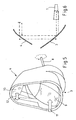
- the in the FIGS. 1 and 2 illustrated embodiment includes an antenna 1, preferably a horn antenna, the millimeter waves 2 radiates.
- the millimeter waves 2 impinge on a rotatably mounted, focusing or defocusing quasi-optical element 3, from which they are reflected and bundled at the same time.
- the element 3 is a rotating focusing mirror, which deflects the beams 2 in the direction of a reflector 4 and focuses on this, so that the point 5 highest bundling lies on the reflector 4 and is moved along with this along a circle.
- the reflector 4 is shaped such that, in cooperation with the rotating component 3, the surface 6 to be imaged is scanned in a circle, as in FIG FIG. 1 is shown.
- the point 5 highest bundling, so the reflection point on the reflector 4, has such a small extent that it can be regarded as a virtual antenna, which generates a beam 7 with a large opening angle in the far field. This large aperture angle is required for good resolution using SAR algorithms.
- the generated beam 7 scans the test object to be examined circular.
- the transmitting and receiving system is horizontal (in FIG. 1 out of the drawing plane) or vertically (in FIG. 1 up and down), so that overall the test object is scanned two-dimensionally. If the entire transmission and reception arrangement is moved around the examination object, it is also possible to scan from different views.
- the quasi-optical, the waves arriving from the antenna 1 incoming or defocusing element 3 and the reflector 4 are rotatably mounted about a common axis of rotation and at the same angular velocity.
- the embodiments show the preferred embodiments in which the quasi-optical element 3 and the reflector 4 are each designed as a mirror with focusing effect.
- the quasi-optical element 3 and the reflector 4 are designed and arranged so that the falling of the antenna 1 on the quasi-optical element 3 central beam parallel to the central beam of the diverging beam, the leaves the reflector 4.
- the quasi-optical element 3 and the reflector 4 are arranged in a common component which is rotatably mounted about a rotation axis 8.
- the component is connected to a rotary drive, that its axis of rotation 8 coincides approximately with the central beam of the emanating from the antenna 1 beam.
- the axis of rotation 8 thus extends approximately centrally through the element 3 and inclined to the mirror surface 9, as from FIG. 1 can be seen.
- the element containing the element 3 and the reflector 4 is made of a lightweight, low-inertia material. It contains a mirror surface 9 of the quasi-optical element 3, from which the rays incident from the antenna 1 are focused onto the subsequently arranged mirror surface 10 of the reflector 4.
- the mirror surface 10 of the reflector 4 which rotates about the axis of rotation, thus serves as a virtual antenna for the SAR evaluation.
- the mirror surfaces 9, 10 of the quasi-optical element 3 and the reflector 4 are designed and arranged such that the incident on the quasi-optical element central beam is parallel to the central beam, which leaves the reflector 4.
- a component which contains the quasi-optical element 3 and the reflector 4 in a so-called Z-arrangement.
- the mirror surface 9 of the element 3 and the mirror surface 10 of the reflector are arranged so that a beam incident from the rear (arrow 11) impinges on the mirror surface 9, bundled by this to the mirror surface 10 of the reflector 4 is deflected and then divergent parallel to incident beam (arrow 11) and in the front direction of the component exits (arrow 12).
- the transmission case is described above in each case. Since the beam path is reciprocal, the system works accordingly in the case of reception.
- Send and receive signal separated by suitable components for example, characterized in that the antenna 1 is connected via couplers, circulators and / or an array of polarizing gratings with a transmitting or receiving device.
- the antenna 1 is built up from at least one transmitting antenna and at least one spatially separated receiving antenna.
Landscapes
- Engineering & Computer Science (AREA)
- Remote Sensing (AREA)
- Radar, Positioning & Navigation (AREA)
- Physics & Mathematics (AREA)
- General Physics & Mathematics (AREA)
- Computer Networks & Wireless Communication (AREA)
- Electromagnetism (AREA)
- Aerials With Secondary Devices (AREA)
- Radar Systems Or Details Thereof (AREA)
- Geophysics And Detection Of Objects (AREA)
- Variable-Direction Aerials And Aerial Arrays (AREA)
- Testing Electric Properties And Detecting Electric Faults (AREA)
- Testing, Inspecting, Measuring Of Stereoscopic Televisions And Televisions (AREA)
Description
- Die Erfindung betrifft eine Vorrichtung zur Abbildung von Prüfobjekten mittels elektromagnetischer Wellen mit folgenden Merkmalen:
- eine Antenne (1), die elektromagnetische Wellen, insbesondere Millimeterwellen, ausstrahlt,
- Mittel zur räumlichen Bündelung der ausgestrahlten Wellen und
- Mittel zur Manipulation der Wellen an der Stelle (5) hoher Bündelung derart, dass diese Stelle (5) als bewegte virtuelle Antenne für eine SAR-Auswertung dient, wobei
- - - die Mittel zur räumlichen Bündelung ein rotierbar gelagertes, fokussierendes oder defokussierendes quasi-optisches Element und
- - - die Mittel zur Manipulation der Wellen an der Stelle (5) hoher Bündelung einen Reflektor (4) enthalten.
- Bei eine in Dokument
WO 2006/088845 beschriebene Vorrichtung zur Abbildung von Prüfobjekten werden mittels eines optischen Sytems elektromagnetische Wellen auf ein Prüfobjekt fokussiert und das Prüfobjekt abgetastet.
Bei einer derartigen, in der deutschen Patentanmeldung10 2005 042 463 beschriebenen - Vorrichtung der gattungsgemäßen Art werden zur Kontrolle von Personen oder Gepäckstücken (nachfolgend als Prüfobjekte bezeichnet) auf versteckte gefährliche Gegenstände (Waffen, Explosivstoffe) die Prüfobjekte mit Millimeterwellen abgescannt, um verdächtige Gegenstände zu detektieren. Dabei wird das Prüfobjekt entlang seines Umfangs sukzessiv mit Millimeterwellen beleuchtet, die gestreuten Wellen werden empfangen und für eine bildhafte Darstellung des Prüfobjekts nach dem SAR-Prinzip ausgewertet.
- Die in der
DE 10 2005 042 463 beschriebene Vorrichtung ermöglicht es, ein zweidimensionales SAR-Verfahren anzuwenden, das sowohl in X- als auch in Y-Richtung eine hohe Auflösung ermöglicht. Durch die Verwendung von bewegbaren virtuellen Antennen lässt sich das SAR-Verfahren realisieren, ohne dass komplexe Antennenansteuerungen erforderlich sind. - Der Erfindung liegt die Aufgabe zugrunde, eine Vorrichtung der gattungsgemäßen Art so zu verbessern, dass sie eine verbesserte Auflösung bei geringerer Verzerrung mit geringerem apparativem Aufwand ermöglicht.
- Zur Lösung dieser Aufgabe sind das quasi-optische, fokussierende oder defokussierende Element und der Reflektor um eine gemeinsame Drehachse mit gleicher Winkelgeschwindigkeit rotierbar gelagert. Diese Konstruktion ermöglicht vergrößerte Öffnungswinkel der elektromagnetischen Strahlung. Diese führen sowohl zu einem vergrößerten Abtastbereich des Prüfobjekts, als auch zu einer vergrößerten Apertur der virtuellen Antenne für die SAR-Auswertung. Der Abstand zwischen der Drehachse des fokussierenden oder defokussierenden Elements und der virtuellen Antenne kann möglichst groß gestaltet werden, um einen großen Abtastbereich auf dem Prüfobjekt zu erhalten.
- Die abhängigen Ansprüche enthalten bevorzugte, da besonders vorteilhafte Ausgestaltungen einer erfindungsgemäßen Vorrichtung:
- Die Anordnung des quasi-optischen, fokussierenden oder defokussierenden Elements und des Reflektors in einem gemeinsamen, rotierbar gelagerten Bauteil nach Patentanspruch 2 ist konstruktiv vorteilhaft.
- Durch die Gestaltung des Reflektors als fokussierend oder defokussierend für die elektromagnetischen Wellen erhält man nach Art eines Teleskops zwei fokussierende oder defokussierende Elemente. Dies ermöglicht eine verzehrungsfreie Gestaltung der bewegten virtuellen Quelle.
- Eine Gestaltung sowohl des quasi-optischen Elements als auch des Reflektors als fokussierend ergibt einen teleskopartigen kompakten Aufbau.
- Bevorzugt sind das quasi-optische Element und der Reflektor als Spiegel gestaltet. Eine möglichst einfach zu steuernde auszuwertende Bewegung der virtuellen Antenne ergibt sich, wenn nach Patentanspruch 6 das quasi-optische Element und der Reflektor so gestaltet und angeordnet sind, dass der auf das quasi-optische Element einfallende Zentralstrahl parallel zu dem Zentralstrahl verläuft, der den Reflektor verlässt.
- Nachfolgend wird die Erfindung anhand zweier Ausführungsbeispiele näher erläutert.
- Figur 1
- zeigt als Prinzipskizze die Funktion der Vorrichtung,
- Figur 2
- zeigt die Rückansicht und
- Figur 3
- die Vorderansicht einer Vorrichtung mit Z-förmigen Strahlengang,
- Figur 4
- zeigt den Strahlengang im Querschnitt,
- Figur 5
- zeigt eine andere Vorrichtung mit U-förmigen Strahlengang,
- Figur 6
- zeigt im Querschnitt den Strahlengang dieser Vorrichtung.
- Die in den Figuren dargestellten Vorrichtungen sind jeweils Teil einer Prüfvorrichtung, die zur Kontrolle von Flugpassagieren auf einem Flughafen dient. Mit der Prüfvorrichtung werden die Flugpassagiere beim Check-in auf verdächtige Gegenstände wie Waffen oder Explosivstoffe geprüft. Die zur Beleuchtung der Prüfobjekte verwendeten elektromagnetischen Wellen haben eine Frequenz zwischen 1 GHz und 10 THz. Bevorzugt werden Millimeterwellen mit einer Frequenz zwischen 30 GHz und 300 GHz verwendet. Zum Empfang der reflektierten Wellen können entweder die Sendeantennen selbst oder getrennte Empfangsantennen verwendet werden.
- Bevorzugt enthält die Prüfvorrichtung eine Plattform, auf der sich das Prüfobjekt, beispielsweise ein Flugpassagier, befindet, während die Kontrolle durchgeführt wird. Nach einer Ausführungsform rotieren die Sende- und Empfangssysteme um das stillstehende Prüfobjekt, um es entlang seines Umfangs sukzessiv mit Millimeterwellen zu beleuchten. Alternativ ist es auch möglich, das Prüfobjekt selbst auf einer Plattform vor einem ortsfest angeordneten Sende- und Empfangssystem rotieren zu lassen.
- Weiterhin enthält die Prüfvorrichtung ein Auswertesystem mit entsprechender Rechnerleistung, von dem die empfangenen, vom Prüfobjekt gestreuten Wellen nach dem SAR-Prinzip ausgewertet werden, um eine bildhafte Darstellung des Prüfobjekts zu erhalten. Die erstellten Bilder werden einer Bedienungsperson auf entsprechenden Anzeigegeräten angezeigt.
- Die in den
Figuren 1 und2 dargestellte Ausführungsform enthält eine Antenne 1, bevorzugt eine Hornantenne, die Millimeterwellen 2 abstrahlt. Die Millimeterwellen 2 treffen auf ein rotierbar gelagertes, fokussierendes oder defokussierendes quasi-optisches Element 3, von dem sie reflektiert und zugleich gebündelt werden. Bevorzugt ist das Element 3 ein rotierender fokussierender Spiegel, der die Strahlen 2 in Richtung zu einem Reflektor 4 ablenkt und auf diesem bündelt, so dass die Stelle 5 höchster Bündelung auf dem Reflektor 4 liegt und mit diesem entlang eines Kreises bewegt wird. Der Reflektor 4 ist so geformt, dass im Zusammenwirken mit dem sich drehenden Bauelement 3 die abzubildende Fläche 6 kreisförmig abgetastet wird, wie inFigur 1 dargestellt ist. - Die Stelle 5 höchster Bündelung, also der Reflektionspunkt auf dem Reflektor 4, hat eine so geringe Ausdehnung, dass sie als virtuelle Antenne betrachtet werden kann, die im Fernfeld ein Strahlenbündel 7 mit großem Öffnungswinkel erzeugt. Dieser große Öffnungswinkel ist für eine gute Auflösung mit Hilfe von SAR-Algorithmen erforderlich. Das erzeugte Strahlenbündel 7 tastet das zu untersuchende Prüfobjekt kreisförmig ab.
- Zusätzlich wird das Sende- und Empfangssystem horizontal (in
Figur 1 aus der Zeichenebene heraus) oder vertikal (inFigur 1 nach oben und unten) bewegt, so dass insgesamt das Prüfobjekt zweidimensional abgetastet wird. Wird die gesamte Sende- und Empfangsanordnung um das Prüfungsobjekt herum bewegt, so ist auch eine Abtastung aus verschiedenen Ansichten möglich. - Wesentlich für die Erfindung ist, dass das quasi-optische, die von der Antenne 1 ankommenden Wellen fokussierende oder defokussierende Element 3 und der Reflektor 4 um eine gemeinsame Drehachse und mit gleicher Winkelgeschwindigkeit rotierbar gelagert sind. Die Ausführungsbeispiele zeigen die bevorzugten Ausführungsformen, bei denen das quasi-optische Element 3 und der Reflektor 4 jeweils als Spiegel mit fokussierender Wirkung gestaltet sind. Für eine möglichst kompakte Bauweise und eine vereinfachte Auswertung sind das quasi-optische Element 3 und der Reflektor 4 so gestaltet und angeordnet, dass der von der Antenne 1 auf das quasi-optische Element 3 fallende Zentralstrahl parallel zu dem Zentralstrahl des divergierenden Strahlenbündels verläuft, das den Reflektor 4 verlässt.
- Bei beiden in der Zeichnung dargestellten Ausführungsformen sind das quasi-optische Element 3 und der Reflektor 4 in einem gemeinsamen Bauteil angeordnet, das um eine Drehachse 8 rotierbar gelagert ist. Bevorzugt ist das Bauteil so mit einem Drehantrieb verbunden, dass seine Drehachse 8 in etwa mit dem Zentralstrahl des von der Antenne 1 ausgehenden Strahlenbündels zusammenfällt. Die Drehachse 8 verläuft somit in etwa mittig durch das Element 3 und geneigt zu dessen Spiegelfläche 9, wie aus
Figur 1 zu entnehmen ist. Das das Element 3 und den Reflektor 4 enthaltende Bauteil ist aus einem leichten, trägheitsarmen Material gefertigt. Es enthält eine Spiegelfläche 9 des quasi-optischen Elements 3, von der die von der Antenne 1 einfallenden Strahlen auf die nachfolgend angeordnete Spiegelfläche 10 des Reflektors 4 fokussiert werden. Die um die Drehachse rotierende Spiegelfläche 10 des Reflektors 4 dient somit als virtuelle Antenne für die SAR-Auswertung. Bei beiden Ausführungsformen sind die Spiegelflächen 9, 10 des quasi-optischen Elements 3 und des Reflektors 4 so gestaltet und angeordnet, dass der auf das quasi-optische Element einfallende Zentralstrahl parallel zu dem Zentralstrahl verläuft, der den Reflektor 4 verlässt. - In den
Figuren 2 und 3 ist ein Bauteil dargestellt, das das quasi-optische Element 3 und den Reflektor 4 in einer so genannten Z-Anordnung enthält. Dabei sind die Spiegelfläche 9 des Elements 3 und die Spiegelfläche 10 des Reflektors so angeordnet, dass ein von hinten einfallender Strahl (Pfeil 11) auf die Spiegelfläche 9 auftrifft, von dieser gebündelt zu der Spiegelfläche 10 des Reflektors 4 umgelenkt wird und anschließend divergierend parallel zum einfallenden Strahl (Pfeil 11) und in dessen Richtung vorne aus dem Bauteil austritt (Pfeil 12). - Bei der alternativen U-Anordnung nach
Figur 5 trifft der einfallende Strahl 11 auf die Spiegelfläche 9 des quasi-optischen Elements 3 und wird - wie bei der Ausführungsform nachFigur 2 - von dieser nach oben auf die Spiegelfläche 10 des Reflektors 4 umgelenkt. Die Spiegelfläche 10 ist so angeordnet, dass das von ihr reflektierte divergierende Strahlenbündel (Pfeil 12) gegen die Einfallrichtung des von der Antenne 1 einfallenden Strahles (Pfeil 11) wieder aus dem Bauteil austritt. Auch bei dieser Ausführungsform verläuft der Zentralstrahl des austretenden divergierenden Strahlenbündels (Pfeil 12) parallel zu dem Zentralstrahl des einfallenden Strahlenbündels (Pfeil 11). - Vorstehend wird jeweils der Sendefall beschrieben. Da der Strahlengang reziprok ist, arbeitet das System im Empfangsfall entsprechend. Sende- und Empfangssignal werden durch geeignete Bauelemente getrennt, beispielsweise dadurch, dass die Antenne 1 über Koppler, über Zirkulatoren und/oder über eine Anordnung aus Polarisationsgittern mit einer Sende- bzw. Empfangseinrichtung verbunden ist.
- Ebenfalls ist der Einsatz zweier räumlich dicht nebeneinander positionierter Antennen oder Antennensysteme anstelle einer Einzelantenne 1 möglich, die jeweils Sende- oder Empfangsfunktion haben. Dann baut sich die Antenne 1 aus mindestens einer Sendeantenne und mindestens einer räumlich getrennten Empfangsantenne auf.
Claims (6)
- Vorrichtung zur Abbildung von Prüfobjekten mittels elektromagnetischer Wellen, insbesondere zur Kontrolle von Personen auf verdächtige Gegenstände, mit folgenden Merkmalen:- eine Antenne (1), die elektromagnetische Wellen, insbesondere Millimeterwellen, ausstrahlt,- Mittel zur räumlichen Bündelung der ausgestrahlten Wellen und- Mittel zur Manipulation der Wellen an der Stelle (5) hoher Bündelung derart, das diese Stelle (5) als bewegte virtuelle Antenne für eine SAR-Auswertung dient, wobeiund wobei das quasi-optische Element (3) und der Reflektor um eine gemeinsame Drehachse (8) und mit gleicher Winkelgeschwindigkeit rotierbar gelagert sind.- - die. Mittel zur räumlichen Bündelung ein rotierbar gelagertes, fokussierendes oder defokussierendes, quasi-optisches Element und- - die Mittel zur Manipulation der Wellen an der Stelle (5) hoher Bündelung einen Reflektor (4),enthalten,
- Vorrichtung nach Anspruch 1, dadurch gekennzeichnet, dass das quasi-optische Element (3) und der Reflektor (4) in einem gemeinsamen Bauteil angeordnet sind, das rotierbar gelagert ist.
- Vorrichtung nach Anspruch 1 oder 2, dadurch gekennzeichnet, dass auch der Reflektor (4) als die elektromagnetischen Wellen fokussierend oder defokussierend gestaltet ist.
- Vorrichtung nach Anspruch 3, dadurch gekennzeichnet, dass sowohl das quasi-optische Element (3) als auch der Reflektor (4) fokussierend gestaltet sind.
- Vorrichtung nach Anspruch 4, dadurch gekennzeichnet, dass das quasi-optische Element (3) und der Reflektor (4) als Spiegel gestaltet sind.
- Vorrichtung nach einem der Ansprüche 1 bis 5, dadurch gekennzeichnet, dass das quasi-optische Element (3) und der Reflektor (4) so gestaltet und angeordnet sind, dass der auf das quasi-optische Element (3) einfallende Zentralstrahl parallel zu dem Zentralstrahl verläuft, der den Reflektor (4) verlässt.
Applications Claiming Priority (2)
| Application Number | Priority Date | Filing Date | Title |
|---|---|---|---|
| DE102007008871 | 2007-02-21 | ||
| PCT/EP2008/001073 WO2008101619A1 (de) | 2007-02-21 | 2008-02-13 | Vorrichtung zur abbildung von prüfobjekten mittels elektromagnetischer wellen, insbesondere zur kontrolle von personen auf verdächtige gegenstände |
Publications (2)
| Publication Number | Publication Date |
|---|---|
| EP2126606A1 EP2126606A1 (de) | 2009-12-02 |
| EP2126606B1 true EP2126606B1 (de) | 2010-07-14 |
Family
ID=39432481
Family Applications (1)
| Application Number | Title | Priority Date | Filing Date |
|---|---|---|---|
| EP08707687A Active EP2126606B1 (de) | 2007-02-21 | 2008-02-13 | Vorrichtung zur abbildung von prüfobjekten mittels elektromagnetischer wellen, insbesondere zur kontrolle von personen auf verdächtige gegenstände |
Country Status (8)
| Country | Link |
|---|---|
| US (1) | US8169355B2 (de) |
| EP (1) | EP2126606B1 (de) |
| CN (1) | CN101646956B (de) |
| AT (1) | ATE474237T1 (de) |
| CA (1) | CA2677947C (de) |
| DE (1) | DE502008000955D1 (de) |
| RU (1) | RU2442187C2 (de) |
| WO (1) | WO2008101619A1 (de) |
Families Citing this family (12)
| Publication number | Priority date | Publication date | Assignee | Title |
|---|---|---|---|---|
| US8253620B2 (en) * | 2009-07-23 | 2012-08-28 | Northrop Grumman Systems Corporation | Synthesized aperture three-dimensional radar imaging |
| EP2697671A2 (de) * | 2011-04-15 | 2014-02-19 | Ariel-University Research and Development Company, Ltd | Passiver millimeterwellendetektor |
| DE102011078539A1 (de) * | 2011-06-08 | 2012-12-13 | Rohde & Schwarz Gmbh & Co. Kg | Verfahren und Vorrichtung zur Erweiterung der Ausleuchtung eines Prüfobjekts |
| EP2773978A1 (de) * | 2011-10-31 | 2014-09-10 | Raytheon Company | Verfahren und vorrichtung zur grossräumigen radardetektion synthetischer aperturen |
| DE102012204174B4 (de) * | 2012-03-16 | 2022-03-10 | Rohde & Schwarz GmbH & Co. Kommanditgesellschaft | Verfahren, System und Kalibrierobjekt zur automatischen Kalibrierung einer bildgebenden Antennenanordnung |
| US20140028494A1 (en) * | 2012-07-26 | 2014-01-30 | The Aerospace Corporation | Virtual Aperture Radar |
| CN104641508A (zh) * | 2012-09-18 | 2015-05-20 | 日本电气株式会社 | 反射器装置、使用反射器装置的通信系统和通信方法 |
| US9316734B2 (en) * | 2012-10-19 | 2016-04-19 | The Curators Of The University Of Missouri | Free-hand scanning and imaging |
| US10222467B2 (en) * | 2015-11-10 | 2019-03-05 | Northrop Grumman Systems Corporation | Two-way coded aperture three-dimensional radar imaging |
| US10416094B2 (en) | 2016-03-31 | 2019-09-17 | Northeastern University | Characterization of dielectric slabs attached to the body using focused millimeter waves |
| US11115792B2 (en) * | 2017-06-15 | 2021-09-07 | Jiejun Kong | Vehicular high-speed network system |
| WO2021070428A1 (ja) * | 2019-10-09 | 2021-04-15 | パナソニックIpマネジメント株式会社 | 撮影装置 |
Family Cites Families (24)
| Publication number | Priority date | Publication date | Assignee | Title |
|---|---|---|---|---|
| US5034750A (en) * | 1983-10-31 | 1991-07-23 | Raytheon Company | Pulse radar and components therefor |
| US5091730A (en) * | 1983-10-31 | 1992-02-25 | Raytheon Company | Pulse radar and components therefor |
| US4652885A (en) * | 1985-03-04 | 1987-03-24 | The United States Of America As Represented By The Secretary Of The Army | Dual mode antenna for millimeter wave and infrared radiation |
| US4901084A (en) * | 1988-04-19 | 1990-02-13 | Millitech Corporation | Object detection and location system |
| US4910523A (en) * | 1987-11-06 | 1990-03-20 | Millitech Corporation | Micrometer wave imaging device |
| US5202692A (en) * | 1986-06-16 | 1993-04-13 | Millitech Corporation | Millimeter wave imaging sensors, sources and systems |
| DE3637000A1 (de) * | 1986-10-31 | 1988-05-05 | Diehl Gmbh & Co | Pruefeinrichtung, insbesondere fuer den suchkopf intelligenter lenkmunition |
| CA1234911A (en) * | 1987-07-16 | 1988-04-05 | Anthony R. Raab | Frequency-scanning radiometer |
| US5047783A (en) * | 1987-11-06 | 1991-09-10 | Millitech Corporation | Millimeter-wave imaging system |
| DE3801626C1 (en) * | 1988-01-21 | 1988-12-29 | Daimler-Benz Ag, 7000 Stuttgart, De | Rotating circular scanner, working according to the triangulation principle, as optical seam position sensor for a welding torch |
| US5227800A (en) * | 1988-04-19 | 1993-07-13 | Millitech Corporation | Contraband detection system |
| CH674898A5 (de) * | 1988-07-06 | 1990-07-31 | Wild Leitz Ag | |
| US5170169A (en) * | 1991-05-31 | 1992-12-08 | Millitech Corporation | Quasi-optical transmission/reflection switch and millimeter-wave imaging system using the same |
| US5298909A (en) * | 1991-12-11 | 1994-03-29 | The Boeing Company | Coaxial multiple-mode antenna system |
| US5760397A (en) * | 1996-05-22 | 1998-06-02 | Huguenin; G. Richard | Millimeter wave imaging system |
| US6777684B1 (en) * | 1999-08-23 | 2004-08-17 | Rose Research L.L.C. | Systems and methods for millimeter and sub-millimeter wave imaging |
| US6480141B1 (en) * | 2001-03-13 | 2002-11-12 | Sandia Corporation | Detection of contraband using microwave radiation |
| US6492955B1 (en) * | 2001-10-02 | 2002-12-10 | Ems Technologies Canada, Ltd. | Steerable antenna system with fixed feed source |
| WO2005086620A2 (en) * | 2003-10-10 | 2005-09-22 | L-3 Communications Security And Detection Systems | Mmw contraband screening system |
| US7626400B2 (en) * | 2005-02-15 | 2009-12-01 | Walleye Technologies, Inc. | Electromagnetic scanning imager |
| CN100487433C (zh) * | 2005-06-07 | 2009-05-13 | 中国科学院安徽光学精密机械研究所 | 基于拉曼光源的车载测污激光雷达装置 |
| DE102005042463A1 (de) * | 2005-09-07 | 2007-03-22 | Smiths Heimann Gmbh | Verfahren und Vorrichtung zur Abbildung von Prüfobjekten mittels elektro-magnetischer Wellen, insbesondere zur Kontrolle von Personen auf verdächtige Gegenstände |
| DE102006006962A1 (de) * | 2006-02-14 | 2007-08-16 | Smiths Heimann Gmbh | Verfahren und Vorrichtung zur hochauflösenden Abbildung von Prüfobjekten mittels elektromagnetischer Wellen, insbesondere zur Kontrolle von Personen auf verdächtige Gegenstände |
| CN100543493C (zh) * | 2006-04-18 | 2009-09-23 | 中国科学院安徽光学精密机械研究所 | 基于f-p标准具的多普勒测风激光雷达的结构及其探测方法 |
-
2008
- 2008-02-13 AT AT08707687T patent/ATE474237T1/de active
- 2008-02-13 RU RU2009135075/28A patent/RU2442187C2/ru active
- 2008-02-13 CN CN2008800057271A patent/CN101646956B/zh active Active
- 2008-02-13 DE DE502008000955T patent/DE502008000955D1/de active Active
- 2008-02-13 WO PCT/EP2008/001073 patent/WO2008101619A1/de not_active Ceased
- 2008-02-13 CA CA2677947A patent/CA2677947C/en active Active
- 2008-02-13 EP EP08707687A patent/EP2126606B1/de active Active
-
2009
- 2009-08-21 US US12/545,534 patent/US8169355B2/en active Active
Also Published As
| Publication number | Publication date |
|---|---|
| RU2009135075A (ru) | 2011-03-27 |
| CA2677947A1 (en) | 2008-08-28 |
| CN101646956B (zh) | 2012-05-30 |
| HK1140265A1 (en) | 2010-12-17 |
| WO2008101619A1 (de) | 2008-08-28 |
| CN101646956A (zh) | 2010-02-10 |
| CA2677947C (en) | 2015-10-13 |
| EP2126606A1 (de) | 2009-12-02 |
| US20100045514A1 (en) | 2010-02-25 |
| RU2442187C2 (ru) | 2012-02-10 |
| DE502008000955D1 (de) | 2010-08-26 |
| US8169355B2 (en) | 2012-05-01 |
| ATE474237T1 (de) | 2010-07-15 |
Similar Documents
| Publication | Publication Date | Title |
|---|---|---|
| EP2126606A1 (de) | Vorrichtung zur abbildung von prüfobjekten mittels elektromagnetischer wellen, insbesondere zur kontrolle von personen auf verdächtige gegenstände | |
| DE102008013066B3 (de) | Vorrichtung zur zweidimensionalen Abbildung von Szenen durch Mikrowellen-Abtastung und Verwendung der Vorrichtung | |
| DE102012025281A1 (de) | Optische Objekterfassungseinrichtung mit einem MEMS und Kraftfahrzeug mit einer solchen Erfassungseinrichtung | |
| EP1922561B1 (de) | Verfahren und vorrichtung zur abbildung von prüfobjekten mittels elektromagnetischer wellen, insbesondere zur kontrolle von personen auf verdächtige gegenstände | |
| DE102008011350A1 (de) | Vorrichtung und Verfahren zur Echtzeiterfassung von elektromagnetischer THz-Strahlung | |
| DE102005016106A1 (de) | Verfahren und Vorrichtung zur Abbildung von Prüfobjekten mit Hilfe von Millimeterwellen, insbesondere zur Kontrolle von Personen auf verdächtige Gegenstände | |
| EP1984758B1 (de) | Verfahren und vorrichtung zur hochauflösenden abbildung von prüfobjekten | |
| EP2837950A1 (de) | Radar-Strahlablenkungseinheit für ein Füllstandradar | |
| DE60014246T2 (de) | Vorrichtung zur Messung von Charakteristiken eines elektromagnetischen Feldes, inbesondere für einen Antennestrahlungsdiagramm | |
| EP2567255B1 (de) | Vorrichtung zur überprüfung eines objektes, insbesondere zur kontrolle von personen auf verdächtige gegenstände | |
| DE102005036527B4 (de) | Röntgen-CT-Prüfanlage sowie CT-Verfahren zur Prüfung von Objekten | |
| EP2361391B1 (de) | Vorrichtung und verfahren zum abbilden eines objekts mit elektromagnetischer hochfrequenzstrahlung | |
| WO2018215399A1 (de) | Verfahren und vorrichtung zum abtasten eines raumwinkels | |
| DE102018204708A1 (de) | Makroskopische Lidar-Vorrichtung | |
| DE102010033951B4 (de) | Anordnung und Verfahren zur mehrdimensionalen Messung von Schwingungen eines Objekts | |
| DE102015118822A1 (de) | Scanvorrichtung | |
| EP3346259B1 (de) | Anordnung zur elektromagnetischen transmissionsmessung an objekten | |
| WO2021083805A1 (de) | Lidar-vorrichtung mit gekrümmtem linsenarray zum emittieren von teilstrahlen | |
| DE102019200764A1 (de) | Optisches System, insbesondere LiDAR-System, sowie Fahrzeug | |
| DE102022213944A1 (de) | LIDAR-Sensor und Verfahren zur optischen Erfassung eines Sichtfeldes | |
| EP3827268B1 (de) | Vorrichtung zur ermittlung einer geschwindigkeitskomponente eines objekts | |
| DE102016101134A1 (de) | Optische Messvorrichtung eines Fahrzeugs, Fahrerassistenzeinrichtung und Fahrzeug mit wenigstens einer optischen Messvorrichtung | |
| WO2015018384A1 (de) | Spektroskopische vorrichtung zur untersuchung von postsendungen mittels terahertz-wellen | |
| DE102014111987A1 (de) | Vorrichtung zur Bestimmung eines Füllstands eines Schüttguts | |
| DE202024104650U1 (de) | Messvorrichtung und System zum Ermitteln eines von einer externen Strahlungsquelle ausgehenden vierdimensionalen elektromagnetischen Strahlungsfeldes |
Legal Events
| Date | Code | Title | Description |
|---|---|---|---|
| PUAI | Public reference made under article 153(3) epc to a published international application that has entered the european phase |
Free format text: ORIGINAL CODE: 0009012 |
|
| 17P | Request for examination filed |
Effective date: 20090720 |
|
| AK | Designated contracting states |
Kind code of ref document: A1 Designated state(s): AT BE BG CH CY CZ DE DK EE ES FI FR GB GR HR HU IE IS IT LI LT LU LV MC MT NL NO PL PT RO SE SI SK TR |
|
| GRAP | Despatch of communication of intention to grant a patent |
Free format text: ORIGINAL CODE: EPIDOSNIGR1 |
|
| DAX | Request for extension of the european patent (deleted) | ||
| GRAS | Grant fee paid |
Free format text: ORIGINAL CODE: EPIDOSNIGR3 |
|
| GRAA | (expected) grant |
Free format text: ORIGINAL CODE: 0009210 |
|
| AK | Designated contracting states |
Kind code of ref document: B1 Designated state(s): AT BE BG CH CY CZ DE DK EE ES FI FR GB GR HR HU IE IS IT LI LT LU LV MC MT NL NO PL PT RO SE SI SK TR |
|
| REG | Reference to a national code |
Ref country code: GB Ref legal event code: FG4D Free format text: NOT ENGLISH |
|
| REG | Reference to a national code |
Ref country code: CH Ref legal event code: EP |
|
| REG | Reference to a national code |
Ref country code: IE Ref legal event code: FG4D |
|
| REF | Corresponds to: |
Ref document number: 502008000955 Country of ref document: DE Date of ref document: 20100826 Kind code of ref document: P |
|
| REG | Reference to a national code |
Ref country code: NL Ref legal event code: T3 |
|
| LTIE | Lt: invalidation of european patent or patent extension |
Effective date: 20100714 |
|
| PG25 | Lapsed in a contracting state [announced via postgrant information from national office to epo] |
Ref country code: FI Free format text: LAPSE BECAUSE OF FAILURE TO SUBMIT A TRANSLATION OF THE DESCRIPTION OR TO PAY THE FEE WITHIN THE PRESCRIBED TIME-LIMIT Effective date: 20100714 Ref country code: LT Free format text: LAPSE BECAUSE OF FAILURE TO SUBMIT A TRANSLATION OF THE DESCRIPTION OR TO PAY THE FEE WITHIN THE PRESCRIBED TIME-LIMIT Effective date: 20100714 Ref country code: NO Free format text: LAPSE BECAUSE OF FAILURE TO SUBMIT A TRANSLATION OF THE DESCRIPTION OR TO PAY THE FEE WITHIN THE PRESCRIBED TIME-LIMIT Effective date: 20101014 |
|
| PG25 | Lapsed in a contracting state [announced via postgrant information from national office to epo] |
Ref country code: PL Free format text: LAPSE BECAUSE OF FAILURE TO SUBMIT A TRANSLATION OF THE DESCRIPTION OR TO PAY THE FEE WITHIN THE PRESCRIBED TIME-LIMIT Effective date: 20100714 Ref country code: IS Free format text: LAPSE BECAUSE OF FAILURE TO SUBMIT A TRANSLATION OF THE DESCRIPTION OR TO PAY THE FEE WITHIN THE PRESCRIBED TIME-LIMIT Effective date: 20101114 Ref country code: HR Free format text: LAPSE BECAUSE OF FAILURE TO SUBMIT A TRANSLATION OF THE DESCRIPTION OR TO PAY THE FEE WITHIN THE PRESCRIBED TIME-LIMIT Effective date: 20100714 Ref country code: SI Free format text: LAPSE BECAUSE OF FAILURE TO SUBMIT A TRANSLATION OF THE DESCRIPTION OR TO PAY THE FEE WITHIN THE PRESCRIBED TIME-LIMIT Effective date: 20100714 Ref country code: CY Free format text: LAPSE BECAUSE OF FAILURE TO SUBMIT A TRANSLATION OF THE DESCRIPTION OR TO PAY THE FEE WITHIN THE PRESCRIBED TIME-LIMIT Effective date: 20100714 Ref country code: BG Free format text: LAPSE BECAUSE OF FAILURE TO SUBMIT A TRANSLATION OF THE DESCRIPTION OR TO PAY THE FEE WITHIN THE PRESCRIBED TIME-LIMIT Effective date: 20101014 |
|
| PG25 | Lapsed in a contracting state [announced via postgrant information from national office to epo] |
Ref country code: SE Free format text: LAPSE BECAUSE OF FAILURE TO SUBMIT A TRANSLATION OF THE DESCRIPTION OR TO PAY THE FEE WITHIN THE PRESCRIBED TIME-LIMIT Effective date: 20100714 Ref country code: LV Free format text: LAPSE BECAUSE OF FAILURE TO SUBMIT A TRANSLATION OF THE DESCRIPTION OR TO PAY THE FEE WITHIN THE PRESCRIBED TIME-LIMIT Effective date: 20100714 Ref country code: GR Free format text: LAPSE BECAUSE OF FAILURE TO SUBMIT A TRANSLATION OF THE DESCRIPTION OR TO PAY THE FEE WITHIN THE PRESCRIBED TIME-LIMIT Effective date: 20101015 |
|
| PG25 | Lapsed in a contracting state [announced via postgrant information from national office to epo] |
Ref country code: DK Free format text: LAPSE BECAUSE OF FAILURE TO SUBMIT A TRANSLATION OF THE DESCRIPTION OR TO PAY THE FEE WITHIN THE PRESCRIBED TIME-LIMIT Effective date: 20100714 |
|
| PLBE | No opposition filed within time limit |
Free format text: ORIGINAL CODE: 0009261 |
|
| STAA | Information on the status of an ep patent application or granted ep patent |
Free format text: STATUS: NO OPPOSITION FILED WITHIN TIME LIMIT |
|
| PG25 | Lapsed in a contracting state [announced via postgrant information from national office to epo] |
Ref country code: RO Free format text: LAPSE BECAUSE OF FAILURE TO SUBMIT A TRANSLATION OF THE DESCRIPTION OR TO PAY THE FEE WITHIN THE PRESCRIBED TIME-LIMIT Effective date: 20100714 Ref country code: SK Free format text: LAPSE BECAUSE OF FAILURE TO SUBMIT A TRANSLATION OF THE DESCRIPTION OR TO PAY THE FEE WITHIN THE PRESCRIBED TIME-LIMIT Effective date: 20100714 Ref country code: IT Free format text: LAPSE BECAUSE OF FAILURE TO SUBMIT A TRANSLATION OF THE DESCRIPTION OR TO PAY THE FEE WITHIN THE PRESCRIBED TIME-LIMIT Effective date: 20100714 Ref country code: CZ Free format text: LAPSE BECAUSE OF FAILURE TO SUBMIT A TRANSLATION OF THE DESCRIPTION OR TO PAY THE FEE WITHIN THE PRESCRIBED TIME-LIMIT Effective date: 20100714 Ref country code: EE Free format text: LAPSE BECAUSE OF FAILURE TO SUBMIT A TRANSLATION OF THE DESCRIPTION OR TO PAY THE FEE WITHIN THE PRESCRIBED TIME-LIMIT Effective date: 20100714 |
|
| 26N | No opposition filed |
Effective date: 20110415 |
|
| PG25 | Lapsed in a contracting state [announced via postgrant information from national office to epo] |
Ref country code: ES Free format text: LAPSE BECAUSE OF FAILURE TO SUBMIT A TRANSLATION OF THE DESCRIPTION OR TO PAY THE FEE WITHIN THE PRESCRIBED TIME-LIMIT Effective date: 20101025 |
|
| REG | Reference to a national code |
Ref country code: DE Ref legal event code: R097 Ref document number: 502008000955 Country of ref document: DE Effective date: 20110415 |
|
| BERE | Be: lapsed |
Owner name: SMITHS HEIMANN G.M.B.H. Effective date: 20110228 |
|
| PG25 | Lapsed in a contracting state [announced via postgrant information from national office to epo] |
Ref country code: MC Free format text: LAPSE BECAUSE OF NON-PAYMENT OF DUE FEES Effective date: 20110228 |
|
| PG25 | Lapsed in a contracting state [announced via postgrant information from national office to epo] |
Ref country code: BE Free format text: LAPSE BECAUSE OF NON-PAYMENT OF DUE FEES Effective date: 20110228 |
|
| PG25 | Lapsed in a contracting state [announced via postgrant information from national office to epo] |
Ref country code: MT Free format text: LAPSE BECAUSE OF FAILURE TO SUBMIT A TRANSLATION OF THE DESCRIPTION OR TO PAY THE FEE WITHIN THE PRESCRIBED TIME-LIMIT Effective date: 20100714 |
|
| REG | Reference to a national code |
Ref country code: CH Ref legal event code: PL |
|
| PG25 | Lapsed in a contracting state [announced via postgrant information from national office to epo] |
Ref country code: CH Free format text: LAPSE BECAUSE OF NON-PAYMENT OF DUE FEES Effective date: 20120229 Ref country code: LI Free format text: LAPSE BECAUSE OF NON-PAYMENT OF DUE FEES Effective date: 20120229 |
|
| PG25 | Lapsed in a contracting state [announced via postgrant information from national office to epo] |
Ref country code: LU Free format text: LAPSE BECAUSE OF NON-PAYMENT OF DUE FEES Effective date: 20110213 |
|
| PG25 | Lapsed in a contracting state [announced via postgrant information from national office to epo] |
Ref country code: PT Free format text: LAPSE BECAUSE OF NON-PAYMENT OF DUE FEES Effective date: 20100714 |
|
| PG25 | Lapsed in a contracting state [announced via postgrant information from national office to epo] |
Ref country code: TR Free format text: LAPSE BECAUSE OF FAILURE TO SUBMIT A TRANSLATION OF THE DESCRIPTION OR TO PAY THE FEE WITHIN THE PRESCRIBED TIME-LIMIT Effective date: 20100714 |
|
| PG25 | Lapsed in a contracting state [announced via postgrant information from national office to epo] |
Ref country code: HU Free format text: LAPSE BECAUSE OF FAILURE TO SUBMIT A TRANSLATION OF THE DESCRIPTION OR TO PAY THE FEE WITHIN THE PRESCRIBED TIME-LIMIT Effective date: 20100714 |
|
| REG | Reference to a national code |
Ref country code: AT Ref legal event code: MM01 Ref document number: 474237 Country of ref document: AT Kind code of ref document: T Effective date: 20130213 |
|
| PG25 | Lapsed in a contracting state [announced via postgrant information from national office to epo] |
Ref country code: AT Free format text: LAPSE BECAUSE OF NON-PAYMENT OF DUE FEES Effective date: 20130213 |
|
| REG | Reference to a national code |
Ref country code: FR Ref legal event code: PLFP Year of fee payment: 9 |
|
| REG | Reference to a national code |
Ref country code: FR Ref legal event code: PLFP Year of fee payment: 10 |
|
| REG | Reference to a national code |
Ref country code: FR Ref legal event code: PLFP Year of fee payment: 11 |
|
| P01 | Opt-out of the competence of the unified patent court (upc) registered |
Effective date: 20230528 |
|
| PGFP | Annual fee paid to national office [announced via postgrant information from national office to epo] |
Ref country code: NL Payment date: 20251215 Year of fee payment: 19 Ref country code: FR Payment date: 20251208 Year of fee payment: 19 |
|
| PGFP | Annual fee paid to national office [announced via postgrant information from national office to epo] |
Ref country code: IE Payment date: 20251209 Year of fee payment: 19 |
|
| PGFP | Annual fee paid to national office [announced via postgrant information from national office to epo] |
Ref country code: GB Payment date: 20260106 Year of fee payment: 19 |
|
| PGFP | Annual fee paid to national office [announced via postgrant information from national office to epo] |
Ref country code: DE Payment date: 20251216 Year of fee payment: 19 |