EP2127190B1 - Robuste synchronisation für ein zeitduplexsignal - Google Patents
Robuste synchronisation für ein zeitduplexsignal Download PDFInfo
- Publication number
- EP2127190B1 EP2127190B1 EP08707634.5A EP08707634A EP2127190B1 EP 2127190 B1 EP2127190 B1 EP 2127190B1 EP 08707634 A EP08707634 A EP 08707634A EP 2127190 B1 EP2127190 B1 EP 2127190B1
- Authority
- EP
- European Patent Office
- Prior art keywords
- time
- window
- signal
- decision
- division duplex
- Prior art date
- Legal status (The legal status is an assumption and is not a legal conclusion. Google has not performed a legal analysis and makes no representation as to the accuracy of the status listed.)
- Active
Links
Images


Classifications
-
- H—ELECTRICITY
- H04—ELECTRIC COMMUNICATION TECHNIQUE
- H04L—TRANSMISSION OF DIGITAL INFORMATION, e.g. TELEGRAPHIC COMMUNICATION
- H04L7/00—Arrangements for synchronising receiver with transmitter
- H04L7/04—Speed or phase control by synchronisation signals
- H04L7/041—Speed or phase control by synchronisation signals using special codes as synchronising signal
- H04L7/042—Detectors therefor, e.g. correlators, state machines
-
- H—ELECTRICITY
- H04—ELECTRIC COMMUNICATION TECHNIQUE
- H04B—TRANSMISSION
- H04B1/00—Details of transmission systems, not covered by a single one of groups H04B3/00 - H04B13/00; Details of transmission systems not characterised by the medium used for transmission
- H04B1/69—Spread spectrum techniques
- H04B1/707—Spread spectrum techniques using direct sequence modulation
- H04B1/7073—Synchronisation aspects
- H04B1/7075—Synchronisation aspects with code phase acquisition
- H04B1/70754—Setting of search window, i.e. range of code offsets to be searched
-
- H—ELECTRICITY
- H04—ELECTRIC COMMUNICATION TECHNIQUE
- H04W—WIRELESS COMMUNICATION NETWORKS
- H04W56/00—Synchronisation arrangements
- H04W56/0055—Synchronisation arrangements determining timing error of reception due to propagation delay
- H04W56/0065—Synchronisation arrangements determining timing error of reception due to propagation delay using measurement of signal travel time
- H04W56/007—Open loop measurement
- H04W56/0075—Open loop measurement based on arrival time vs. expected arrival time
- H04W56/0085—Open loop measurement based on arrival time vs. expected arrival time detecting a given structure in the signal
Definitions
- the present invention relates to a method, apparatus, and computer program product for synchronizing a receiver to a time division duplex signal.
- cell search is the first step for a terminal device (or user equipment (UE) in 3G terminology) to acquire the enhanced universal territory radio access (EUTRA) system with very limited prior information.
- This procedure includes detecting a synchronization channel (SCH) position, detecting a cell identity (ID), and reading a broadcast channel (BCH).
- SCH synchronization channel
- ID cell identity
- BCH broadcast channel
- Centre frequency an operator related value which may be prestored in the UE
- SCH bandwidth e.g. central 1.25MHz regardless of the operating system bandwidth
- part of the SCH sequence information like repetition times, sequence formats and so on.
- time division duplex (TDD) systems in which different periodic time periods or time slots are allocated to uplink (UL) and downlink (DL) channels will have additional problems due to their TDD nature.
- TDD time division duplex
- One of these problems is that there could be strong UE-to-UE interference between closely located UEs. As an example, such an UE-to-UE interferences may occur when one UE is doing cell search while the other UE is transmitting.
- Fig. 2 shows a situation where a second UE (UE2) starts to search a cell when a close-by first UE (UE1) is transmitting data.
- UE2 a second UE
- UE1 a close-by first UE
- UE-to-UE interference could be that the interfered second UE (UE2) cannot detect the network just because there is strong interference in the UL period or slot of the whole frame of a broadcast signal received from a base station (BS) or other access device.
- BS base station
- Document EP 1 282 257 describes a TDD system with up-link and down-link, where a preamble is detected using an auto -correlation function and a sliding window.
- an apparatus comprising:
- a computer program product comprising code means for producing the steps of the above-defined method when run on a computer device.
- a slide window based normalization with the big time window can be used to make synchronization more robust to interference.
- a higher interference can even be used to achieve better cell detection performance for time division duplex systems, so that auto correlation based synchronization or detection methods, such as the one proposed in proposal R1-060930, "Cell Search procedure of EUTRA TDD system for the initial synchronization", CATT, RITT, can be made more robust to interference.
- the slide window based normalization may only be applied, when a ratio between a difference between a maximum value and a minimum value of a window function and a mean value of said window function is larger than a predetermined value, the window function corresponding to an autocorrelation of the received time division duplex signal within the time window.
- the slide window based normalization may be for example applied by multiplying the decision time metric by an absolute value of a difference between a value of the window function and said mean value of the window function.
- the correlation for the decision time metric may be performed over the length of the replica signal, and the decision time metric may be obtained for a total frame length of the received time division duplex signal.
- the synchronization pattern may indicate a position of a downlink synchronization channel used for accessing a wireless network.
- UTRAN UMTS Terrestrial Radio Access Network
- EUTRA enhanced universal territory radio access
- Fig. 1 shows an exemplary frame structure of one pair of switching points between UL and DL traffic timeslots.
- one radio frame of e.g. 10ms can be divided into two sub-frames of e.g. 5ms.
- Each sub-frame contains seven traffic timeslots and three special timeslots.
- the length of the three special timeslot DwPTS, GP1 and UpPTS between TS0 and TS1 can be set to 275us.
- the special timeslot DwPTS is a downlink initial synchronization timeslot which can be used for cell DL initial synchronization access.
- a DL synchronization pilot or pattern in DwPTS can be searched to obtain an initial synchronization information. Then, DL time synchronization and frequency synchronization can be established through the DwPTS timeslot.
- the timeslot UpPTS is an UL access timeslot which can be used for transmission of an UL synchronization pilot signal.
- the UL synchronization pilot signal is transmitted from the UE to the base station (or "Node B" in 3G terminology) in this timeslot to achieve uplink synchronization.
- the timeslot GP1 between the timeslots DwPTS and UpPTS provides a protection gap for switching from DL to UL.
- the length of GP1 determines the coverage radius of the TDD cell.
- the system can support scaleable transmission bandwidth from 1.25MHz to 20MHz.
- various types of UE with different bandwidth capabilities must be considered.
- Node Bs with various frequency band capabilities must be considered. For instance, a UE with a maximum bandwidth capability of 20 MHz must be able to establish a radio link to a Node B using a scalable bandwidth from 1.25 to 20 MHz.
- a UE with a 5-MHz bandwidth capability must be able to establish a radio link to a base transceiver station (BTS) using a scalable bandwidth.
- BTS base transceiver station
- the SCH design for the timeslot DwPTS should ensure that UEs with different bandwidth capacities can access the system and achieve synchronization. So, the SCH can be defined with a bandwidth of 1.25MHz.
- the SCH can be placed in the DwPTS timeslot every 5ms with a bandwidth of 1.25MHz.
- the BCH is set in timeslot TS0, and it is also allocated within the central 1.25MHz spectrum.
- the UE can obtain basic system information, e.g., system bandwidth.
- the SCH may be composed of an OFDM symbol with sub-carrier spacing of e.g. 15 KHz, so that the duration of the OFDM symbol is 66.67us.
- the bandwidth of the SCH is 1.25 MHz.
- the OFDM symbol parameters may be the same as listed in specification TR25.814 v.1.0.2 "Physical Layer Aspects for Evolved UTRA", Finland, Jan. 25-27, 2006 .
- the cyclic prefix (CP) duration of the OFDM symbol in the SCH may be set to 8 samples (4.165us). It is noted that there may be one SCH used for DL initial synchronization in every DwPTS timeslot. Because the SCH is constructed in one standalone timeslot, the CP duration can be fixed without considering the effects of long and short CP in traffic timeslots on the construction of SCH.
- a UE can utilize the following procedure to realize cell search.
- This procedure enables fast initial synchronization with the TDD system and reception of system broadcast information.
- a first step of the cell search procedure for initial synchronization is coarse time synchronization using the OFDM symbol of the primary SCH.
- one of several (e.g., three) types of OFDM symbols may be sent in the SCH.
- the coarse time synchronization can be obtained using a time domain cross correlation method. Because the UE knows the OFDM symbol sent in the primary SCH, by performing cross correlation between a known OFDM sequence and the received sequence, high synchronization precision can be achieved.
- a cell group identity may be related to the secondary SCH in which one of a number of cell group IDs will be conveyed.
- the UE will find the cell group ID by detecting its pre-known pattern. By detecting cell group ID, the hypothesis which needs to be tested in the following cell ID detecting step will be decreased.
- the cell ID may be related to the first reference symbols within the central 1.25MHz of timeslot TS0.
- the UE can find the cell ID from a received pilot sequence. Different cells use difference pilot sequences, which may be implemented with a pseudo noise (PN) code. Cell ID can then be found by judging the PN code of received pilot sequence from the detected cell group, as described for example in proposal R1-051549, "Cell Search procedure for initial synchronization and neighbour cell identification," Seoul, Korea, Nov. 7-11, 2005 .
- PN pseudo noise
- the UE After time synchronization and frequency error correction, the UE is able to read the system broadcast information.
- Basic system information can be broadcasted through the central 1.25MHz band, so that the UE can obtain basic system configuration information, for example system bandwidth, etc, and finish the cell search process.
- N total frame length of the TDD receiving signal
- L is the length of a local replica of the known synchronization pattern, e.g., OFDM symbol as mentioned above
- s(d) is a sample of the TDD receiving signal
- r(d) is the local replica.
- mod means modulo, because the receiving signal is a periodic signal.
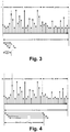
- Fig. 3 shows a schematic signal diagram with a cross correlation window to be used for an additional correlation window based normalization of the windowed receiving signal before cross correlation with a local replica of the known synchronization pattern, e.g., OFDM symbol as mentioned above.
- sampled amplitude values of the receiving signal are shown as arrows. It can be seen that the UL period has strong interference and this may overwhelm the real SCH correlation peaks of the DL period.
- the rationale behind the correlation window based normalization is to utilize the reasons of correlation peaks in the DL period and the correlation peaks in the UL period.
- the first one is caused by strong cross correlation attributes and the second one is caused by strong interference energy. So by normalization, the UL signal can't take advantage of its strong energy to overwhelm the real SCH correlation peaks.
- the SCH position is at the DwPTS special time slot.
- the UL interference which may occur during an initial cell synchronization performance can be expressed with a DL interference to signal ratio (ISR).
- ISR DL interference to signal ratio
- Fig. 4 shows a schematic signal diagram with an enlarged sliding normalization window according to an embodiment.
- W(d) is a window function
- M is the window length.
- M is designed to be long enough to accommodate the whole uplink period.
- the window could be configured to cover 4800 samples to account for 2.5ms.
- the above window function can be conditionally applied to the above decision time metrics, when the below condition is met: max W ⁇ min W / mean W > ⁇ where max is an operation to find the maximum item over the whole window function, min is an operation to find minimum item over the whole window function and mean is an operation to find the average value of the whole window function.
- ⁇ is a parameter which may be set to "1", for example.
- the new decision time metric M'(d) will then supersede the old one for decision making, e.g., as obtained from equation (2).
- Fig. 5 shows a diagram indicating cell detection performance with different ISR ratios and a typical urban (TU) channel.
- the cell detection probability is shown under different ISR ratios for additive white Gaussian noise (AWGN) distribution and a slowly fading channel, such as a TU3 (Typical Urban, speed 3 km/h) channel.
- AWGN additive white Gaussian noise
- TU3 Typical Urban, speed 3 km/h
- Fig. 6 shows a diagram indicating ninety percentile cell detection time at different ISR and channels for a conventional synchronization procedure. More specifically, a ninety percentile cell detection performance curve is shown for TU3 and TU30 channels of different speeds 3km/h and 30km/h. It can be seen that when ISR is 10dB, the UE needs much longer time to detect a cell under both TU3 and TU30 channel. For higher ISR ratios, the UE can't even detect the cell.
- Fig. 7 shows a diagram indicating ninety percentile cell detection time at different ISR and channels after applying cross correlation window based normalization according to the above equation (2). Even at ISR of 100dB, no loss of performance is perceivable, so that the performance is more robust to ISR.
- Fig. 8 shows a diagram indicating ninety percentile cell detection time at different ISR and channels after applying the proposed big normalization window. It can be seen that for ISR higher than 20dB, there is almost 1-2 dB performance gain.
- Fig. 9 shows a flow diagram of a general synchronization procedure according to an embodiment.
- a correlation-window based normalization of a decision time metric is performed, to thereby increase robustness to interference.
- a slide window function is calculated, e.g., based on the above equation (4), as an auto correlation with a time window covering or accommodating the uplink period of the receiver TDD signal.
- step S103 it is checked whether a set condition for applying the window based normalization is met. The condition could be based on the above equation (5) or any other suitable condition reflecting the effect of UL interference. If it is determined in step S103 that the condition is not met, the decision making about the synchronization timing is performed in step S105 using the correlation-window based normalization of step S101, e.g., according to equation (2).
- step S104 the window-based normalization with the big time window is applied in step S104 to the decision time metrics, e.g., as defined in equation (6), to thereby take additional advantage of the interference introduced by the UL period. Then, the procedure advances to step S105 where the decision making about the synchronization timing is performed using the modified window based normalization with big sliding window of step S104.
- Fig. 10 shows a schematic block diagram of a terminal device according to an embodiment, in which the proposed synchronization procedure is implemented by corresponding processing stages.
- This terminal device may be UE, a mobile phone, smart phone or any other type of transmit and receive unit for accessing a wireless network.
- a TDD signal is received on a radio frequency level via an antenna and a transceiver circuit 12. After down conversion, demodulation etc., the signal is supplied to a first processing stage 13, where a correlation-window based normalization of a decision time metric is performed based on a local replica and the received TDD signal, to obtain a signal or sequence M(d). Then, in a second stage which consists of blocks 14, 15 and 17, a slide window based normalization is selectively applied to obtain M'(d).
- the second processing stage includes a slide window function calculation unit 14 which is based on the above equation (4). The output of the calculation unit 14 is supplied to a decision unit 17 configured to check whether a set condition for applying the window based normalization is met.
- the condition could be based on the above equation (5) or any other suitable condition reflecting the effect of UL interference.
- the decision unit 17 determines that the condition is not met, it controls a selection unit 15 to select M(d) and forward it to a cell searching unit 16 configured to perform a cell searching procedure and decide on the synchronization timing.
- the decision making about the synchronization timing is thus performed using the correlation-window based normalization, e.g., according to equation (2), without big slide window based normalization.
- the decision unit 17 determines that the condition is met, it controls the selection unit to select the window-based normalization result M'(d) with the big time window, and forward it to the cell searching unit 16, where optimum synchronization timing is decided.
- Fig. 11 shows a schematic block diagram of a software-based implementation of the proposed functionalities for achieving channel-sensitive complexity adjustment.
- a processing unit 210 which may be any processor or computer device with a control unit which performs control based on software routines of a control program stored in a memory 212.
- Program code instructions are fetched from the memory 212 and are loaded to the control unit of the processing unit 210 in order to perform the processing steps of the above functionalities described in connection with the respective branch selection and signal processing blocks 13 to 17 of Fig. 10 and the flow diagram of Fig. 9 .
- These processing steps may be performed on the basis of input data DI and may generate output data DO, wherein the input data DI may correspond to the samples of the TDD signal, and the output data DO may correspond to the detected synchronization timing of the received TDD signal.
- a method, apparatus, system and computer program product have been described, wherein a time division multiplex signal is received with a periodic first time period allocated to a downlink transmissions and a periodic second time period allocated to uplink transmissions.
- a decision time metric is obtained by correlating the received signal with a replica signal in order to detect a synchronization pattern provided in the first time period. Then, a slide window based normalization with a time window long enough to accommodate said second time period is applied to the decision time metric.
- synchronization can be made more robust to interference for TDD systems.
- a high ISR can even be exploited to achieve even better cell detection performance.
- Two normalization operations can be provided before and after cross correlation for every slide window. The resulting additional processing load is however not very high and can be optimized through some computer algorithm.
- the present invention is not restricted to the above predetermined embodiment with its specific network elements.
- the present invention is applicable to any communication system which provides a downlink synchronization pattern in a signal with a periodic first time period allocated to a downlink transmissions and a periodic second time period allocated to uplink transmissions.
- the preferred embodiment may thus vary within the scope of the attached claims.
Landscapes
- Engineering & Computer Science (AREA)
- Computer Networks & Wireless Communication (AREA)
- Signal Processing (AREA)
- Mobile Radio Communication Systems (AREA)
- Synchronisation In Digital Transmission Systems (AREA)
Claims (14)
- Verfahren, umfassend:Empfangen eines Zeitduplexsignals mit einer periodischen ersten Zeitdauer, die Downlink-Übertragungen zugewiesen ist, und einer periodischen zweiten Zeitdauer, die Uplink-Übertragungen zugewiesen ist;Erhalten einer Entscheidungszeitmetrik durch Korrelieren des empfangenen Signals mit einem Replikatsignal, um ein Synchronisationsmuster zu erkennen, das in der ersten Zeitdauer bereitgestellt wird;Anwenden einer gleitfensterbasierten Normalisierung auf die Entscheidungszeitmetrik, dadurch gekennzeichnet, dass die gleitfensterbasierte Normalisierung mit einem Zeitfenster durchgeführt wird, das lange genug ist, um die zweite Zeitdauer unterzubringen.
- Verfahren nach Anspruch 1, wobei die gleitfensterbasierte Normalisierung nur angewendet wird, wenn ein Verhältnis zwischen einer Differenz zwischen einem Maximalwert und einem Minimalwert einer Fensterfunktion und einem Mittelwert der Fensterfunktion größer als ein vorbestimmter Wert ist, wobei die Fensterfunktion einer Autokorrelation des empfangenen Zeitduplexsignals innerhalb des Zeitfensters entspricht.
- Verfahren nach Anspruch 2, wobei die gleitfensterbasierte Normalisierung durch Multiplizieren der Entscheidungszeitmetrik mit einem absoluten Wert einer Differenz zwischen einem Wert der Fensterfunktion und dem Mittelwert der Fensterfunktion angewendet wird.
- Verfahren nach einem der vorhergehenden Ansprüche, wobei die Korrelation für die Entscheidungszeitmetrik über die Länge des Replikatsignals durchgeführt wird, und die Entscheidungszeitmetrik für eine gesamte Rahmenlänge des empfangenen Zeitduplexsignals erhalten wird.
- Verfahren nach Anspruch 4, wobei das Synchronisationsmuster eine Position eines Downlink-Synchronisationskanals anzeigt, der zum Zugriff auf ein drahtloses Netzwerk verwendet wird.
- Vorrichtung, umfassend:Empfängermittel, konfiguriert zum Empfangen eines Zeitduplexsignals mit einer periodischen ersten Zeitdauer, die Downlink-Übertragungen zugewiesen ist, und einer periodischen zweiten Zeitdauer, die Uplink-Übertragungen zugewiesen ist;erste Verarbeitungsmittel, konfiguriert zum Erhalten einer Entscheidungszeitmetrik durch Korrelieren des empfangenen Signals mit einem Replikatsignal, um ein Synchronisationsmuster zu erkennen, das in der ersten Zeitdauer bereitgestellt wird;zweite Verarbeitungsmittel, konfiguriert zum Anwenden einer gleitfensterbasierten Normalisierung auf die Entscheidungszeitmetrik, dadurch gekennzeichnet, dass die gleitfensterbasierte Normalisierung mit einem Zeitfenster durchgeführt wird, das lange genug ist, um die zweite Zeitdauer unterzubringen.
- Vorrichtung nach Anspruch 6, wobei die zweite Verarbeitungsstufe so konfiguriert ist, dass sie die gleitfensterbasierte Normalisierung nur anwendet, wenn ein Verhältnis zwischen einer Differenz zwischen einem Maximalwert und einem Minimalwert einer Fensterfunktion und einem Mittelwert der Fensterfunktion größer als ein vorbestimmter Wert ist, wobei die Fensterfunktion einer Autokorrelation des empfangenen Zeitduplexsignals innerhalb des Zeitfensters entspricht.
- Vorrichtung nach Anspruch 7, wobei die zweite Verarbeitungsstufe so konfiguriert ist, dass sie die gleitfensterbasierte Normalisierung durch Multiplizieren der Entscheidungszeitmetrik mit einem absoluten Wert einer Differenz zwischen einem Wert der Fensterfunktion und dem Mittelwert der Fensterfunktion anwendet.
- Vorrichtung nach einem der Ansprüche 6 bis 8, wobei die erste Verarbeitungsstufe so konfiguriert ist, dass sie die Korrelation für die Entscheidungszeitmetrik über die Länge des Replikatsignals durchführt und die Entscheidungszeitmetrik für eine gesamte Rahmenlänge des empfangenen Zeitduplexsignals erhält.
- Vorrichtung nach einem der Ansprüche 6 bis 9, wobei das Synchronisationsmuster eine Position eines Downlink-Synchronisationskanals anzeigt, der zum Zugriff auf ein drahtloses Netzwerk verwendet wird.
- Endgerät, umfassend eine Vorrichtung nach Anspruch 6.
- Empfängermodul, umfassend eine Vorrichtung nach Anspruch 6.
- Kommunikationssystem, umfassend eine Vorrichtung nach Anspruch 6 und eine Basisstation oder Zugriffseinrichtung zum Senden des Zeitduplexsignals per Broadcast.
- Computerprogrammprodukt, umfassend Codemittel zum Erzeugen der Schritte von Verfahrensanspruch 1 bei Ausführung auf einer Computereinrichtung.
Applications Claiming Priority (2)
| Application Number | Priority Date | Filing Date | Title |
|---|---|---|---|
| US88889407P | 2007-02-08 | 2007-02-08 | |
| PCT/EP2008/000989 WO2008095731A1 (en) | 2007-02-08 | 2008-02-08 | Robust synchronization for time division duplex signal |
Publications (2)
| Publication Number | Publication Date |
|---|---|
| EP2127190A1 EP2127190A1 (de) | 2009-12-02 |
| EP2127190B1 true EP2127190B1 (de) | 2017-08-23 |
Family
ID=39428046
Family Applications (1)
| Application Number | Title | Priority Date | Filing Date |
|---|---|---|---|
| EP08707634.5A Active EP2127190B1 (de) | 2007-02-08 | 2008-02-08 | Robuste synchronisation für ein zeitduplexsignal |
Country Status (3)
| Country | Link |
|---|---|
| US (1) | US8401041B2 (de) |
| EP (1) | EP2127190B1 (de) |
| WO (1) | WO2008095731A1 (de) |
Families Citing this family (12)
| Publication number | Priority date | Publication date | Assignee | Title |
|---|---|---|---|---|
| US20080316947A1 (en) * | 2007-06-21 | 2008-12-25 | Bengt Lindoff | METHOD AND APPARATUS FOR 3G LTE FDD and TDD DETECTION USING REFERENCE SIGNAL CORRELATION |
| EP2171956B1 (de) * | 2007-07-13 | 2018-04-11 | Thomson Licensing DTV | Spektralmessung für ofdm signale mittels pilottönen |
| US8184654B2 (en) * | 2008-10-03 | 2012-05-22 | Motorola Solutions, Inc. | Method for ending a call session in a communication system |
| US8358968B2 (en) * | 2008-10-03 | 2013-01-22 | Motorola Solutions, Inc. | Method for selecting a channel to be monitored by subscriber units that are idle in a communication system |
| US8045499B2 (en) * | 2008-10-03 | 2011-10-25 | Motorola Solutions, Inc. | Method of communicating which channel is to be monitored by subscriber units that are idle in a communication system |
| US8139597B2 (en) * | 2008-10-03 | 2012-03-20 | Motorola Solutions, Inc. | Method for trunking radio frequency resources |
| US8279991B2 (en) * | 2008-10-03 | 2012-10-02 | Motorola Solutions, Inc. | Method of efficiently synchronizing to a desired timeslot in a time division multiple access communication system |
| US8503409B2 (en) | 2010-04-15 | 2013-08-06 | Motorola Solutions, Inc. | Method for direct mode channel access |
| US8599826B2 (en) | 2010-04-15 | 2013-12-03 | Motorola Solutions, Inc. | Method for synchronizing direct mode time division multiple access (TDMA) transmissions |
| US8462766B2 (en) | 2011-03-07 | 2013-06-11 | Motorola Solutions, Inc. | Methods and apparatus for diffusing channel timing among subscriber units in TDMA direct mode |
| FR3049413B1 (fr) * | 2016-03-22 | 2022-11-18 | Sigfox | Procede de correction d'une erreur sur la generation de frequence par un terminal d'un systeme de communication sans fil |
| KR102416552B1 (ko) * | 2017-09-29 | 2022-07-04 | 주식회사 케이엠더블유 | 시분할 이중화 방식을 사용하는 분산 안테나 시스템의 tdd 서브-시스템 |
Family Cites Families (10)
| Publication number | Priority date | Publication date | Assignee | Title |
|---|---|---|---|---|
| US4295223A (en) * | 1979-04-25 | 1981-10-13 | Westinghouse Electric Corp. | Digital signal/noise ratio amplifier apparatus for a communication system |
| US5177740A (en) * | 1991-09-03 | 1993-01-05 | General Electric Company | Frame/slot synchronization for U.S. digital cellular TDMA radio telephone system |
| US5473612A (en) * | 1994-11-28 | 1995-12-05 | Motorola, Inc. | Method and apparatus for minimizing false detection of packet data in a communication receiver |
| US6650904B1 (en) * | 1999-12-16 | 2003-11-18 | Ericsson Inc. | Optimization of radio receiver uplink power |
| EP1282257A1 (de) * | 2001-08-02 | 2003-02-05 | Mitsubishi Electric Information Technology Centre Europe B.V. | Verfahren und Vorrichtung zur Detektion von Datensequenzen |
| KR100880480B1 (ko) * | 2002-02-21 | 2009-01-28 | 엘지전자 주식회사 | 디지털 오디오 신호의 실시간 음악/음성 식별 방법 및시스템 |
| US7321610B2 (en) * | 2002-03-19 | 2008-01-22 | Industrial Technology Research Institute | Method and system of interference cancellation in multi-cell CDMA systems |
| US7421013B1 (en) * | 2004-08-02 | 2008-09-02 | Marvell International Ltd. | Maximum likelihood estimation of time and frequency offset for OFDM systems |
| WO2006047851A1 (en) * | 2004-11-02 | 2006-05-11 | Nortel Networks Limited | Systems and methods for use with orthogonal frequency division multiplexing |
| ATE467137T1 (de) * | 2006-03-03 | 2010-05-15 | Europ Agence Spatiale | Verfahren zum verarbeiten von positionsbestimmungssignalen insbesondere für innenanwendungen |
-
2008
- 2008-02-08 EP EP08707634.5A patent/EP2127190B1/de active Active
- 2008-02-08 US US12/028,278 patent/US8401041B2/en active Active
- 2008-02-08 WO PCT/EP2008/000989 patent/WO2008095731A1/en not_active Ceased
Non-Patent Citations (1)
| Title |
|---|
| None * |
Also Published As
| Publication number | Publication date |
|---|---|
| EP2127190A1 (de) | 2009-12-02 |
| US20080219191A1 (en) | 2008-09-11 |
| US8401041B2 (en) | 2013-03-19 |
| WO2008095731A1 (en) | 2008-08-14 |
Similar Documents
| Publication | Publication Date | Title |
|---|---|---|
| EP2127190B1 (de) | Robuste synchronisation für ein zeitduplexsignal | |
| US7315566B2 (en) | Mobile communication system, channel synchronization establishing method, and mobile station | |
| US7894417B2 (en) | Signal arrangement for multi-bandwidth OFDM system | |
| RU2462817C1 (ru) | Способ передачи пилот-сигнала, базовая станция, мобильная станция и система сотовой связи, в которой применен этот способ | |
| CN104113503B (zh) | 有频率偏移的lte小区搜索方法及装置 | |
| US8280421B2 (en) | Terminal device and base station device | |
| US20090202021A1 (en) | Frequency offset compensation for detecting random access channel prefix | |
| US20080043702A1 (en) | Method and apparatus for cell search in a communication system | |
| US20050195791A1 (en) | Apparatus and method for assigning a ranging channel and transmitting and receiving a ranging signal in an OFDM system | |
| EP2804356B1 (de) | Verfahren und vorrichtung für direktzugriff in einem kommunikationssystem | |
| EP3158703B1 (de) | Signalformat zur zellensuche und -synchronisierung in drahtlosen netzwerken | |
| US20070270273A1 (en) | Method and apparatus for fast cell search | |
| US7990932B2 (en) | Apparatus, method and computer program product providing initial cell acquisition and pilot sequence detection | |
| US20030147358A1 (en) | Radio base station apparatus and communication terminal | |
| EP2621110A1 (de) | Referenzsignalerzeugungsvorrichtung und präambelsequenzerkennungsvorrichtung damit | |
| US8526321B2 (en) | Method and device for detecting of transmitting antenna configuration in long term evolution system | |
| KR101790530B1 (ko) | 고주파 대역을 지원하는 무선 접속 시스템에서 단계별 상향링크 동기 신호 검출 방법 및 장치 | |
| EP3907951B1 (de) | Systeme und verfahren zur lokalisierung gültiger lte-kanäle eines lte-bandes | |
| US9893925B1 (en) | Method and apparatus for joint time and frequency synchronization in wireless communication systems | |
| US9942772B2 (en) | Node and method for dynamic synchronization of communications for a wireless device | |
| CN101399607B (zh) | 一种无线通信系统中的测距方法和装置 | |
| EP2624479A1 (de) | Vorrichtung zur erkennung von präambelsequenzen | |
| WO2001028145A1 (en) | Apparatus, and associated method, for detecting a symbol sequence | |
| US8514803B2 (en) | Non-coherent detection method of the number of transmit antenna ports for OFDMA | |
| Almenar et al. | Synchronization techniques for HIPERLAN/2 |
Legal Events
| Date | Code | Title | Description |
|---|---|---|---|
| PUAI | Public reference made under article 153(3) epc to a published international application that has entered the european phase |
Free format text: ORIGINAL CODE: 0009012 |
|
| 17P | Request for examination filed |
Effective date: 20090826 |
|
| AK | Designated contracting states |
Kind code of ref document: A1 Designated state(s): AT BE BG CH CY CZ DE DK EE ES FI FR GB GR HR HU IE IS IT LI LT LU LV MC MT NL NO PL PT RO SE SI SK TR |
|
| DAX | Request for extension of the european patent (deleted) | ||
| RAP1 | Party data changed (applicant data changed or rights of an application transferred) |
Owner name: NOKIA CORPORATION |
|
| RAP1 | Party data changed (applicant data changed or rights of an application transferred) |
Owner name: NOKIA TECHNOLOGIES OY |
|
| GRAP | Despatch of communication of intention to grant a patent |
Free format text: ORIGINAL CODE: EPIDOSNIGR1 |
|
| INTG | Intention to grant announced |
Effective date: 20170329 |
|
| GRAS | Grant fee paid |
Free format text: ORIGINAL CODE: EPIDOSNIGR3 |
|
| GRAA | (expected) grant |
Free format text: ORIGINAL CODE: 0009210 |
|
| AK | Designated contracting states |
Kind code of ref document: B1 Designated state(s): AT BE BG CH CY CZ DE DK EE ES FI FR GB GR HR HU IE IS IT LI LT LU LV MC MT NL NO PL PT RO SE SI SK TR |
|
| REG | Reference to a national code |
Ref country code: GB Ref legal event code: FG4D |
|
| REG | Reference to a national code |
Ref country code: CH Ref legal event code: EP |
|
| REG | Reference to a national code |
Ref country code: AT Ref legal event code: REF Ref document number: 922386 Country of ref document: AT Kind code of ref document: T Effective date: 20170915 |
|
| REG | Reference to a national code |
Ref country code: IE Ref legal event code: FG4D |
|
| REG | Reference to a national code |
Ref country code: DE Ref legal event code: R096 Ref document number: 602008051738 Country of ref document: DE |
|
| REG | Reference to a national code |
Ref country code: NL Ref legal event code: FP |
|
| REG | Reference to a national code |
Ref country code: LT Ref legal event code: MG4D |
|
| REG | Reference to a national code |
Ref country code: AT Ref legal event code: MK05 Ref document number: 922386 Country of ref document: AT Kind code of ref document: T Effective date: 20170823 |
|
| PG25 | Lapsed in a contracting state [announced via postgrant information from national office to epo] |
Ref country code: AT Free format text: LAPSE BECAUSE OF FAILURE TO SUBMIT A TRANSLATION OF THE DESCRIPTION OR TO PAY THE FEE WITHIN THE PRESCRIBED TIME-LIMIT Effective date: 20170823 Ref country code: SE Free format text: LAPSE BECAUSE OF FAILURE TO SUBMIT A TRANSLATION OF THE DESCRIPTION OR TO PAY THE FEE WITHIN THE PRESCRIBED TIME-LIMIT Effective date: 20170823 Ref country code: LT Free format text: LAPSE BECAUSE OF FAILURE TO SUBMIT A TRANSLATION OF THE DESCRIPTION OR TO PAY THE FEE WITHIN THE PRESCRIBED TIME-LIMIT Effective date: 20170823 Ref country code: NO Free format text: LAPSE BECAUSE OF FAILURE TO SUBMIT A TRANSLATION OF THE DESCRIPTION OR TO PAY THE FEE WITHIN THE PRESCRIBED TIME-LIMIT Effective date: 20171123 Ref country code: FI Free format text: LAPSE BECAUSE OF FAILURE TO SUBMIT A TRANSLATION OF THE DESCRIPTION OR TO PAY THE FEE WITHIN THE PRESCRIBED TIME-LIMIT Effective date: 20170823 Ref country code: HR Free format text: LAPSE BECAUSE OF FAILURE TO SUBMIT A TRANSLATION OF THE DESCRIPTION OR TO PAY THE FEE WITHIN THE PRESCRIBED TIME-LIMIT Effective date: 20170823 |
|
| PG25 | Lapsed in a contracting state [announced via postgrant information from national office to epo] |
Ref country code: LV Free format text: LAPSE BECAUSE OF FAILURE TO SUBMIT A TRANSLATION OF THE DESCRIPTION OR TO PAY THE FEE WITHIN THE PRESCRIBED TIME-LIMIT Effective date: 20170823 Ref country code: IS Free format text: LAPSE BECAUSE OF FAILURE TO SUBMIT A TRANSLATION OF THE DESCRIPTION OR TO PAY THE FEE WITHIN THE PRESCRIBED TIME-LIMIT Effective date: 20171223 Ref country code: PL Free format text: LAPSE BECAUSE OF FAILURE TO SUBMIT A TRANSLATION OF THE DESCRIPTION OR TO PAY THE FEE WITHIN THE PRESCRIBED TIME-LIMIT Effective date: 20170823 Ref country code: ES Free format text: LAPSE BECAUSE OF FAILURE TO SUBMIT A TRANSLATION OF THE DESCRIPTION OR TO PAY THE FEE WITHIN THE PRESCRIBED TIME-LIMIT Effective date: 20170823 Ref country code: BG Free format text: LAPSE BECAUSE OF FAILURE TO SUBMIT A TRANSLATION OF THE DESCRIPTION OR TO PAY THE FEE WITHIN THE PRESCRIBED TIME-LIMIT Effective date: 20171123 Ref country code: GR Free format text: LAPSE BECAUSE OF FAILURE TO SUBMIT A TRANSLATION OF THE DESCRIPTION OR TO PAY THE FEE WITHIN THE PRESCRIBED TIME-LIMIT Effective date: 20171124 |
|
| PG25 | Lapsed in a contracting state [announced via postgrant information from national office to epo] |
Ref country code: RO Free format text: LAPSE BECAUSE OF FAILURE TO SUBMIT A TRANSLATION OF THE DESCRIPTION OR TO PAY THE FEE WITHIN THE PRESCRIBED TIME-LIMIT Effective date: 20170823 Ref country code: DK Free format text: LAPSE BECAUSE OF FAILURE TO SUBMIT A TRANSLATION OF THE DESCRIPTION OR TO PAY THE FEE WITHIN THE PRESCRIBED TIME-LIMIT Effective date: 20170823 Ref country code: CZ Free format text: LAPSE BECAUSE OF FAILURE TO SUBMIT A TRANSLATION OF THE DESCRIPTION OR TO PAY THE FEE WITHIN THE PRESCRIBED TIME-LIMIT Effective date: 20170823 |
|
| REG | Reference to a national code |
Ref country code: DE Ref legal event code: R097 Ref document number: 602008051738 Country of ref document: DE |
|
| PG25 | Lapsed in a contracting state [announced via postgrant information from national office to epo] |
Ref country code: SK Free format text: LAPSE BECAUSE OF FAILURE TO SUBMIT A TRANSLATION OF THE DESCRIPTION OR TO PAY THE FEE WITHIN THE PRESCRIBED TIME-LIMIT Effective date: 20170823 Ref country code: EE Free format text: LAPSE BECAUSE OF FAILURE TO SUBMIT A TRANSLATION OF THE DESCRIPTION OR TO PAY THE FEE WITHIN THE PRESCRIBED TIME-LIMIT Effective date: 20170823 Ref country code: IT Free format text: LAPSE BECAUSE OF FAILURE TO SUBMIT A TRANSLATION OF THE DESCRIPTION OR TO PAY THE FEE WITHIN THE PRESCRIBED TIME-LIMIT Effective date: 20170823 |
|
| PLBE | No opposition filed within time limit |
Free format text: ORIGINAL CODE: 0009261 |
|
| STAA | Information on the status of an ep patent application or granted ep patent |
Free format text: STATUS: NO OPPOSITION FILED WITHIN TIME LIMIT |
|
| 26N | No opposition filed |
Effective date: 20180524 |
|
| PG25 | Lapsed in a contracting state [announced via postgrant information from national office to epo] |
Ref country code: SI Free format text: LAPSE BECAUSE OF FAILURE TO SUBMIT A TRANSLATION OF THE DESCRIPTION OR TO PAY THE FEE WITHIN THE PRESCRIBED TIME-LIMIT Effective date: 20170823 |
|
| REG | Reference to a national code |
Ref country code: CH Ref legal event code: PL |
|
| PG25 | Lapsed in a contracting state [announced via postgrant information from national office to epo] |
Ref country code: MC Free format text: LAPSE BECAUSE OF FAILURE TO SUBMIT A TRANSLATION OF THE DESCRIPTION OR TO PAY THE FEE WITHIN THE PRESCRIBED TIME-LIMIT Effective date: 20170823 |
|
| REG | Reference to a national code |
Ref country code: BE Ref legal event code: MM Effective date: 20180228 |
|
| PG25 | Lapsed in a contracting state [announced via postgrant information from national office to epo] |
Ref country code: CH Free format text: LAPSE BECAUSE OF NON-PAYMENT OF DUE FEES Effective date: 20180228 Ref country code: LI Free format text: LAPSE BECAUSE OF NON-PAYMENT OF DUE FEES Effective date: 20180228 Ref country code: LU Free format text: LAPSE BECAUSE OF NON-PAYMENT OF DUE FEES Effective date: 20180208 |
|
| REG | Reference to a national code |
Ref country code: FR Ref legal event code: ST Effective date: 20181031 |
|
| REG | Reference to a national code |
Ref country code: IE Ref legal event code: MM4A |
|
| PG25 | Lapsed in a contracting state [announced via postgrant information from national office to epo] |
Ref country code: IE Free format text: LAPSE BECAUSE OF NON-PAYMENT OF DUE FEES Effective date: 20180208 |
|
| PG25 | Lapsed in a contracting state [announced via postgrant information from national office to epo] |
Ref country code: FR Free format text: LAPSE BECAUSE OF NON-PAYMENT OF DUE FEES Effective date: 20180228 Ref country code: BE Free format text: LAPSE BECAUSE OF NON-PAYMENT OF DUE FEES Effective date: 20180228 |
|
| PG25 | Lapsed in a contracting state [announced via postgrant information from national office to epo] |
Ref country code: MT Free format text: LAPSE BECAUSE OF NON-PAYMENT OF DUE FEES Effective date: 20180208 |
|
| PG25 | Lapsed in a contracting state [announced via postgrant information from national office to epo] |
Ref country code: TR Free format text: LAPSE BECAUSE OF FAILURE TO SUBMIT A TRANSLATION OF THE DESCRIPTION OR TO PAY THE FEE WITHIN THE PRESCRIBED TIME-LIMIT Effective date: 20170823 |
|
| PG25 | Lapsed in a contracting state [announced via postgrant information from national office to epo] |
Ref country code: HU Free format text: LAPSE BECAUSE OF FAILURE TO SUBMIT A TRANSLATION OF THE DESCRIPTION OR TO PAY THE FEE WITHIN THE PRESCRIBED TIME-LIMIT; INVALID AB INITIO Effective date: 20080208 Ref country code: PT Free format text: LAPSE BECAUSE OF FAILURE TO SUBMIT A TRANSLATION OF THE DESCRIPTION OR TO PAY THE FEE WITHIN THE PRESCRIBED TIME-LIMIT Effective date: 20170823 |
|
| PG25 | Lapsed in a contracting state [announced via postgrant information from national office to epo] |
Ref country code: CY Free format text: LAPSE BECAUSE OF FAILURE TO SUBMIT A TRANSLATION OF THE DESCRIPTION OR TO PAY THE FEE WITHIN THE PRESCRIBED TIME-LIMIT Effective date: 20170823 |
|
| P01 | Opt-out of the competence of the unified patent court (upc) registered |
Effective date: 20230527 |
|
| PGFP | Annual fee paid to national office [announced via postgrant information from national office to epo] |
Ref country code: NL Payment date: 20260106 Year of fee payment: 19 |
|
| PGFP | Annual fee paid to national office [announced via postgrant information from national office to epo] |
Ref country code: GB Payment date: 20260106 Year of fee payment: 19 |
|
| PGFP | Annual fee paid to national office [announced via postgrant information from national office to epo] |
Ref country code: DE Payment date: 20251230 Year of fee payment: 19 |