EP2127244B1 - Techniken für verbesserte fehlerdetektion in einem drahtlosen kommunikationssystem - Google Patents
Techniken für verbesserte fehlerdetektion in einem drahtlosen kommunikationssystem Download PDFInfo
- Publication number
- EP2127244B1 EP2127244B1 EP08719755.4A EP08719755A EP2127244B1 EP 2127244 B1 EP2127244 B1 EP 2127244B1 EP 08719755 A EP08719755 A EP 08719755A EP 2127244 B1 EP2127244 B1 EP 2127244B1
- Authority
- EP
- European Patent Office
- Prior art keywords
- data
- ack
- nack
- cqi
- allocation information
- Prior art date
- Legal status (The legal status is an assumption and is not a legal conclusion. Google has not performed a legal analysis and makes no representation as to the accuracy of the status listed.)
- Active
Links
Images


Classifications
-
- H—ELECTRICITY
- H04—ELECTRIC COMMUNICATION TECHNIQUE
- H04L—TRANSMISSION OF DIGITAL INFORMATION, e.g. TELEGRAPHIC COMMUNICATION
- H04L1/00—Arrangements for detecting or preventing errors in the information received
- H04L1/0001—Systems modifying transmission characteristics according to link quality, e.g. power backoff
- H04L1/0023—Systems modifying transmission characteristics according to link quality, e.g. power backoff characterised by the signalling
- H04L1/0027—Scheduling of signalling, e.g. occurrence thereof
-
- H—ELECTRICITY
- H04—ELECTRIC COMMUNICATION TECHNIQUE
- H04L—TRANSMISSION OF DIGITAL INFORMATION, e.g. TELEGRAPHIC COMMUNICATION
- H04L1/00—Arrangements for detecting or preventing errors in the information received
- H04L1/12—Arrangements for detecting or preventing errors in the information received by using return channel
-
- H—ELECTRICITY
- H04—ELECTRIC COMMUNICATION TECHNIQUE
- H04B—TRANSMISSION
- H04B7/00—Radio transmission systems, i.e. using radiation field
- H04B7/02—Diversity systems; Multi-antenna system, i.e. transmission or reception using multiple antennas
- H04B7/04—Diversity systems; Multi-antenna system, i.e. transmission or reception using multiple antennas using two or more spaced independent antennas
- H04B7/0413—MIMO systems
-
- H—ELECTRICITY
- H04—ELECTRIC COMMUNICATION TECHNIQUE
- H04L—TRANSMISSION OF DIGITAL INFORMATION, e.g. TELEGRAPHIC COMMUNICATION
- H04L1/00—Arrangements for detecting or preventing errors in the information received
- H04L1/12—Arrangements for detecting or preventing errors in the information received by using return channel
- H04L1/16—Arrangements for detecting or preventing errors in the information received by using return channel in which the return channel carries supervisory signals, e.g. repetition request signals
-
- H—ELECTRICITY
- H04—ELECTRIC COMMUNICATION TECHNIQUE
- H04W—WIRELESS COMMUNICATION NETWORKS
- H04W72/00—Local resource management
- H04W72/12—Wireless traffic scheduling
- H04W72/1263—Mapping of traffic onto schedule, e.g. scheduled allocation or multiplexing of flows
-
- H—ELECTRICITY
- H04—ELECTRIC COMMUNICATION TECHNIQUE
- H04W—WIRELESS COMMUNICATION NETWORKS
- H04W72/00—Local resource management
- H04W72/20—Control channels or signalling for resource management
-
- H—ELECTRICITY
- H04—ELECTRIC COMMUNICATION TECHNIQUE
- H04W—WIRELESS COMMUNICATION NETWORKS
- H04W72/00—Local resource management
- H04W72/20—Control channels or signalling for resource management
- H04W72/23—Control channels or signalling for resource management in the downlink direction of a wireless link, i.e. towards a terminal
-
- H—ELECTRICITY
- H04—ELECTRIC COMMUNICATION TECHNIQUE
- H04L—TRANSMISSION OF DIGITAL INFORMATION, e.g. TELEGRAPHIC COMMUNICATION
- H04L1/00—Arrangements for detecting or preventing errors in the information received
- H04L1/12—Arrangements for detecting or preventing errors in the information received by using return channel
- H04L1/16—Arrangements for detecting or preventing errors in the information received by using return channel in which the return channel carries supervisory signals, e.g. repetition request signals
- H04L1/18—Automatic repetition systems, e.g. Van Duuren systems
- H04L1/1829—Arrangements specially adapted for the receiver end
- H04L1/1854—Scheduling and prioritising arrangements
Definitions
- the exemplary and non-limiting embodiments of this invention relate generally to wireless communication systems, apparatus, methods and computer program products and, more specifically, relate to error detection.
- E-UTRAN A proposed communication system known as E-UTRAN or LTE is currently under discussion within the 3GPP.
- the E-UTRAN system is a packet-based system that operates under strict control by the BS (Node B).
- the usage of physical UL/DL resources is signaled from the Node B to the UE, typically in each TTI.
- the signaling is realized by use of UL and DL ATs.
- the UL and DL ATs indicate to the UE which physical resources are assigned for UL and DL data transmissions, respectively.
- a working assumption in the 3GPP is that the UL and DL ATs are separately encoded (e.g., error (1) or (2)). Error (3) may occur, for example, in the situation where the UL and DL ATs are jointly coded.
- the error rate related to the resource allocation signaling is assumed to be on the order of 1% - 5%.
- the ACK/NACK for the data packet that is indicated by the DL AT will likely be associated with a different TTI than the ACK/NACK for the UL AT (e.g., UL data). This is due to the fact that ACK/NACK signaling cannot be transmitted until the corresponding DL data packet has been decoded. This is in contrast to the UL data since the UL data can be transmitted immediately once the UL AT has been correctly received.
- US 2006/0195576 discloses a method of transmitting allocation information in a communications system for indicating sets of transmission resources to communications devices. At least one allocation rule is defined for associating sequences of sets of transmission resources with the communications devices. The communications device monitors allocation information of sets of transmission resources associated with it.
- United States patent application publication number US 2006/0029011 A1 relates to methods and apparatus for notifying mobile stations in an inactive state of the presence of uplink or downlink channel configuration, broadcast system updates, traffic channel allocations and paging messages.
- UL Allocation (AT) Fails The scheduled UL data will not be transmitted (DTX) until the failure has been detected and the correct UL AT has been transmitted and received. It is possible for data-non-associated control signals (e.g., CQI, ACK/NACK) to be sent using one or more shared control resources instead of dedicated resources. If the receiver design is not good enough, periodic CQI may also be lost.
- data-non-associated control signals e.g., CQI, ACK/NACK
- DL Allocation (AT) Fails DL data will be lost.
- the Node B will be trying to detect an ACK/NACK that has not been sent (DTX for ACK/NACK).
- DTX for ACK/NACK
- the control signal multiplexing design is not good enough, UL data and periodic CQI may also be lost.
- data-non-associated control signals e.g., CQI, ACK/NACK
- Both UL and DL ATs Fail Both UL and DL data will be lost.
- UL control signal transmission There are two assumptions that should be noted regarding UL control signal transmission. It is assumed that periodic CQI is free from signaling errors. For example, in the case where both UL and DL fail, it is assumed that periodic CQI remains unaffected and is received correctly. It is further assumed that additional data-associated signaling is not used to signal the actual UL control signaling format. That is, no additional signaling is used to specify whether or not ACK/NACK is present (e.g., multiplexed with the UL data).
- the Node B In order for the Node B to receive the control signals properly (i.e., on the correct frequency/time resource(s)), the Node B should be able to identify possible signaling errors. This enables the Node B to respond to and account for signaling errors, for example, by transmitting on different resources or by knowing to look elsewhere for various signals (e.g., ACK/NACK, CQI). Thus, it is desirable to identify the actual control signaling format (DTX detection), at least to some extent. It is also desirable to design and utilize multiplexing schemes that minimize problems caused by erroneous DTX detection.
- DTX detection the actual control signaling format
- Table 1 depicts exemplary solutions for the various combinations of data, CQI and ACK/NACK.
- a "+" in one of the first three columns indicates the presence of UL data, CQI and/or ACK/NACK, respectively, while a "-" indicates absence of the same.
- the above-described errors can be represented in a table (e.g., Table 2) using binary notation.
- three bits can be used to indicate the on/off state (i.e., presence/absence) of the UL data, CQI and ACK/NACK, respectively.
- a value of 001 may be used to indicate that there is no UL data or CQI (neither has been received), but there is an ACK/NACK (an ACK/NACK was received).
- This notation may also be used to represent the signals that the Node B should have received, should look for or should transmit.
- CQI may be configured to be transmitted periodically at known times (e.g., known prior to transmission). In such a case, there will not be a misunderstanding about whether CQI is present or absent.
- FIG. 1 depicts a flowchart illustrating one non-limiting example of a procedure the Node B can employ to determine which signals the Node B should have received from a UE.
- the Node B inquires whether an UL AT was received (box 102). Note that if an UL AT is not received and decoded, the Node B cannot receive any UL data. If an UL AT has not been received (NO at box 102), the process proceeds to box 106. If an UL AT has been received (YES at box 102), the Node B inquires whether an UL data DTX has been detected (box 104).
- the possible data-non-associated control channels can be received by the Node B on shared resources.
- the Node B inquires whether the DL AT was received by the UE. That is, the Node B checks to see if the UE sent an ACK for the DL AT. If a DL AT was not received by the UE (NO at box 106, no ACK from UE), then the outcome is box 110 and the signal combination is 010 or 000, depending on whether CQI is on (present) or off (absent), respectively.
- a DL AT was received by the UE (YES at box 106, ACK from UE), the process proceeds to box 108 where the Node B inquires whether an ACK/NACK (A/N) DTX is detected. If an ACK/NACK DTX is not detected (NO at box 108), the outcome is box 110. If an ACK/NACK DTX is detected (YES at box 108), the outcome is box 112 and the signal combination is 011 or 001, depending on whether CQI is on (present) or off (absent), respectively.
- the possible data-non-associated control channels can be received by the Node B on dedicated resources.
- the Node B inquires whether the DL AT was received by the UE. That is, the Node B checks to see if the UE sent an ACK for the DL AT. If a DL AT was not received by the UE (NO at box 114, no ACK from UE), then the outcome is box 118 and the signal combination is 110 or 100, depending on whether CQI is on (present) or off (absent), respectively.
- a DL AT was received by the UE (YES at box 114, ACK from UE), the process proceeds to box 116 where the Node B inquires whether an ACK/NACK (A/N) DTX is detected. If an ACK/NACK DTX is not detected (NO at box 116), the outcome is box 118. If an ACK/NACK DTX is detected (YES at box 116), the outcome is box 120 and the signal combination is 111 or 101, depending on whether CQI is on (present) or off (absent), respectively.
- the UL data DTX detection is generally a significant operation since it determines on which type of resource (shared or dedicated) the possible data-non-associated control channels can be received by the Node B. For example, if the UL AT fails, then the DL control channel(s) (e.g., ACK/NACK, CQI) will be transmitted on a shared control resource. As another non-limiting example, if the UL AT is correctly received, the control signal(s) will be TDM with UL data and transmitted on a dedicated resource. As non-limiting examples, the UL data DTX detection can be based on a SNR or SINR measurement of one or more pilot and/or data signals (e.g., a threshold detector).
- a threshold detector e.g., a threshold detector
- FIG. 2 shows one non-limiting example of shared resources suitable for control signal transmission as explained above.
- FIG. 3 depicts one non-limiting example of dedicated resources suitable for control signal transmission as explained above. Note that the control signals may be multiplexed with UL data, also as explained above.
- the potential failure of a component e.g., UL AT, DL AT, UL data DTX detection
- a device e.g., the base station/Node B
- information e.g., control signals, data
- the possible data-non-associated control channels e.g., ACK/NACK, CQI
- the Node B would still be assuming that the control signals will arrive via dedicated resources.
- the Node B can identify whether or not the UL data is present (i.e., whether or not the UL AT failed).
- the UL data DTX detection fails, it can cause severe problems.
- the UL data DTX detector might indicate that UL data is present although it is not or that UL data is absent when it is present. In both cases, control signals are received from the wrong place, increasing the risk that a NACK or DTX is interpreted as an ACK. In addition, UL data will be lost. There is also a possibility that CQI will be lost.
- UL data DTX detection failure is generally the worst type of failure since higher layer error recovery (e.g., RLC retransmission), which is generally a slow operation and causes significant overhead, may be needed.
- improved DTX detection techniques are provided. If the UL AT fails or if a CRC of the UL AT is negative while the corresponding DL AT has been correctly received by the UE or the UE has periodic control information (e.g., CQI) to be transmitted, as noted above, the UE can transmit the control signals on shared control resources. Therefore, it is desirable to determine if the UL AT has been correctly received by the UE, said determination being based on DTX detection.
- CQI periodic control information
- both shared control resources and dedicated resources are received by the Node B. That is, reception of the shared control channel is performed even though, in the absence of an UL AT failure, the shared control signaling resource should not be in use.
- the improved DTX detector can utilize both signals, for example, by having two decision variables with one variable for each type of resource.
- the decision variable indicates whether or not a signal is present for that resource (e.g., the decision variable can be a binary value). This will significantly decrease the probability of UL data DTX detection failure. This will concurrently improve the quality of data and control signal transmission.
- decision variables one each for shared control resources and dedicated resources, identified below as a shared variable and dedicated variable, wherein the decision variables are binary values that indicate the presence (1) or absence (0) of a signal in the corresponding resource.
- the decision variables are binary values that indicate the presence (1) or absence (0) of a signal in the corresponding resource.
- the UL TTI comprises both data-non-associated control signals (e.g., ACK/NACK, CQI) and UL data.
- data-non-associated control signals e.g., ACK/NACK, CQI
- FIG. 4 shows a diagram of the signals, shared or dedicated, that would be detected based on the potential failure of the UL AT and/or the DL AT in accordance with aspects of the exemplary embodiments of the invention. Detecting a signal only on dedicated resources (a "dedicated signal”) indicates that the UL AT has not failed. Detecting a signal only on shared resources (a "shared signal”) indicates that the UL AT has failed while the DL AT has not failed. Detecting neither a dedicated signal nor a shared signal indicates that both the UL AT and the DL AT have failed. Note that since the focus is on the failure of the UL AT, the case where the UL AT has not failed and the DL AT has failed ("X" in FIG. 4 ) is not considered.
- Table 4 shows the four outcomes and corresponding determinations from the four possible combinations of detecting the presence or absence of signals on shared resources and dedicated resources. The outcomes are further discussed immediately below.
- the dedicated resource may be one used for data transmission while the shared resource may be one used for the transmission of an ACK/NACK or CQI.
- the possible combinations include: data+ACK/NACK, data+CQI and data+CQI+ACK/NACK.
- control channel multiplexing is based on using cyclic shifts of CAZAC codes.
- CDM will be used as the multiplexing scheme between different UEs transmitting only control signals. Due to the properties of cyclic shifts of CAZAC codes, reception of the shared resource is generally straight-forward. This is a beneficial aspect since the above-described exemplary embodiment receives the shared resource. As such, there is relatively little additional complexity (e.g., for the Node B) due to the reception of the shared resource.
- the above-described exemplary embodiment increases the robustness of systems by increasing the probability of identifying UL AT failure.
- the exemplary embodiment also provides faster recovery in the event of an UL AT failure.
- the probability of receiving control signals from the wrong resource e.g., type of resource, wrong location
- the probability of receiving control signals from the wrong resource is decreased, thus also reducing the risk that a DTX is misinterpreted (e.g., as an ACK).
- miscommunication such as an ACK/NACK or CQI getting through even though the UL AT has failed, for example, is reduced.
- the additional complexity for implementing the exemplary embodiment is relatively minor, as noted above.
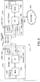
- FIG. 6 a wireless network 612 is adapted for communication with a user equipment (UE) 614 via an access node (AN) 616.
- UE user equipment
- AN access node
- the UE 614 includes: a data processor (DP) 620; a memory (MEM) 622 coupled to the DP 620; a suitable first RF transceiver (TRANS 1) 624 (having a transmitter (TX) and a receiver (RX)) coupled to the DP 620; a first antenna (ANT1) 626 coupled to the TRANS 1 624; a suitable second RF transceiver (TRANS2) 628 (having a transmitter (TX) and a receiver (RX)) coupled to the DP 620; and a second antenna (ANT2) 630 coupled to the TRANS2 628.
- the MEM 622 stores a program (PROG) 632.
- the TRANS1 624 and TRANS2 628 are both capable of bidirectional wireless communication, such as a communication (COM) 634, with the AN 616.
- the AN 616 includes: a data processor (DP) 638; a memory (MEM) 640 coupled to the DP 638; a suitable first RF transceiver (TRANS1) 642 (having a transmitter (TX) and a receiver (RX)) coupled to the DP 638; a first antenna (ANT1) 644 coupled to the TRANS1 642; a suitable second RF transceiver (TRANS2) 646 (having a transmitter (TX) and a receiver (RX)) coupled to the DP 638; and a second antenna (ANT2) 648 coupled to the TRANS2 646.
- the MEM 640 stores a program (PROG) 650.
- the TRANS 1 642 and the TRANS2 646 are both capable of bidirectional wireless communication, such as the COM 634, with the UE 614.
- the AN 616 may be coupled via a data path 652 to one or more external networks or systems, such as the internet 654, for example.
- the transceivers 624, 628, 642, 646 and antennas 626, 630, 644, 648 of the UE 614 and AN 616 may be utilized for MIMO communications via the COM 634.
- the COM 634 may comprise a non-MIMO communication.
- At least one of the PROGs 632, 650 is assumed to include program instructions that, when executed by the associated DP, enable the electronic device to operate in accordance with the exemplary embodiments of this invention, as discussed herein.
- the various embodiments of the UE 614 can include, but are not limited to, cellular phones, personal digital assistants (PDAs) having wireless communication capabilities, portable computers having wireless communication capabilities, image capture devices such as digital cameras having wireless communication capabilities, gaming devices having wireless communication capabilities, music storage and playback appliances having wireless communication capabilities, Internet appliances permitting wireless Internet access and browsing, as well as portable units or terminals that incorporate combinations of such functions.
- PDAs personal digital assistants
- portable computers having wireless communication capabilities
- image capture devices such as digital cameras having wireless communication capabilities
- gaming devices having wireless communication capabilities
- music storage and playback appliances having wireless communication capabilities
- Internet appliances permitting wireless Internet access and browsing, as well as portable units or terminals that incorporate combinations of such functions.
- the embodiments of this invention may be implemented by computer software executable by one or more of the DPs 620, 638 of the UE 614 and the AN 616, or by hardware, or by a combination of software and hardware.
- the MEMs 622, 640 may be of any type suitable to the local technical environment and may be implemented using any suitable data storage technology, such as semiconductor-based memory devices, magnetic memory devices and systems, optical memory devices and systems, fixed memory and removable memory, as non-limiting examples.
- the DPs 620, 638 may be of any type suitable to the local technical environment, and may include one or more of general purpose computers, special purpose computers, microprocessors, digital signal processors (DSPs) and processors based on a multi-core processor architecture, as non-limiting examples.
- the UE 614 and/or the AN 616 may comprise a different number of transceivers and/or antennas.
- the UE and AN may each comprise one transceiver and one antenna.
- the DL AT it is possible for the DL AT to fail.
- various errors can occur. For example, the ACK/NACK associated with/by the DL AT would be missing from the given UL TTI because the UE would have missed the DL allocation and would therefore have no reason to include an ACK/NACK. Since the Node B is unaware of the failure, and thus unaware of the absence of the ACK/NACK, it is likely that the Node B will misinterpret the received signal.
- a DL ACK/NACK (A/N) DTX detector can be used to address this problem by providing an indication when A/N DTX occurs (i.e., to indicate whether or not the DL ACK/NACK is present).
- A/N DTX detection itself fails.
- A/N DTX detection failure There are two situations that may occur regarding A/N DTX detection failure: (AA) the DL AT fails and the A/N DTX detector fails (i.e., does not detect the DL AT failure); or (BB) the DL AT does not fail but the A/N DTX detector fails (e.g., a false alarm). The consequences of these two situations are considered below.
- the ACK/NACK can be: transmitted using CAZAC sequences, multiplexed with CQI (shared control/resources), multiplexed with UL data (dedicated resources) or multiplexed with CQI and UL data, as non-limiting examples.
- ACK/NACK DTX detection can be based, for example, on SNR measurement(s) (e.g., a threshold detector). Proper multiplexing design will likely increase DTX detection probability. Furthermore, a proper multiplexing design between UL data, CQI and ACK/NACK will likely increase the probability of maintaining the CQI and/or UL data reception in the event of a DTX detection failure.
- multiplexing issues There are several multiplexing issues that may have an impact on the performance of the A/N DTX detector. As non-limiting examples, one may consider how to multiplex ACK/NACK and CQI, how to multiplex ACK/NACK and UL data, and/or how to multiplex ACK/NACK, CQI and UL data.
- FIG. 7 depicts exemplary combinations of ACK/NACK and CQI as transmitted with UL data (e.g., multiplexed).
- CQI and ACK/NACK will increase the probability of maintaining the CQI and/or UL data reception in the event that an ACK/NACK is interpreted as a DTX. That is, having substantially similar CQI transmission both with and without an ACK/NACK will likely preserve CQI transmission when A/N DTX detection fails.
- One option is to keep the CQI encoder unchanged and perform the extra repetition for pre-determined ACK/NACK bits (e.g., symbol-level multiplexing between ACK/NACK and CQI).
- DTX detection may be difficult because the repeated CQI may be interpreted as an ACK/NACK.
- Another option is to have substantially similar UL data transmission both with and without an ACK/NACK. This will only partially degrade the UL data reception when A/N DTX detection fails.
- Data rate-matching may be designed such that the UL data is self-decodable in case the UL data is interpreted as an ACK/NACK DTX.
- DTX detection may be difficult because the repeated CQI may be interpreted as an ACK/NACK.
- a third option is to design the CQI encoder scheme such that the cross-correlation between the ACK/NACK/DTX sequences is minimized.
- a fourth option is to design the CQI encoder such that repeated bits (e.g., during ACK/NACK DTX) have optimized cross-correlation with only the ACK sequence.
- UL data e.g., random UL data
- a fifth option is to always send an ACK/NACK when CQI and/or UL data is present.
- this approach increases overhead since aNACK will be transmitted, even when it is unnecessary.
- a sixth option is to signal the ACK/NACK implicitly using the RS (e.g., one cyclic shift corresponds to ACK and another cyclic shift corresponds to NACK).
- the same principle could be used for both shared and dedicated resources. If ACK/NACK is not present, the cyclic shift corresponding to NACK could be selected.
- there are a few problems with this approach First, it may be difficult to provide sufficient coverage for ACK/NACK as there are only two RS symbols per TTI. Second, an incorrect decision (e.g., cyclic shift) will cause some throughput loss for UL data transmission because channel estimation will be compromised. Third, an incorrect decision (e.g., cyclic shift) also may mean that a NACK is interpreted as an ACK or vice versa.
- a seventh option to be used with the sixth option is to increase the number of RS symbols for UEs having coverage problems. This would likely decrease the probability of an incorrect decision (e.g., cyclic shift).
- an additional bit is included in the UL AT (e.g., sent in the DL from the Node B to the UE).
- This additional bit is used, for example, to inform the UE whether or not the corresponding DL AT was transmitted. That is, this additional bit is associated with the DL signaling of the UL resources and tells the UE whether or not the UE should use a bit field for ACK/NACK.
- the UL bit fields reserved may comprise a plurality of bits as opposed to a single bit, for example, depending on the MIMO mode.
- the UE will automatically reserve a predetermined ACK/NACK field (said field comprising at least one bit) from the UL resource, even if the UE had missed (e.g., failed to receive) the corresponding DL AT.
- the UE may respond to the additional bit with, for example, an ACK/NACK in the next UL message to the Node B.
- the ACK/NACK indicates the receipt or non-receipt of, for example, the DL AT by the UE.
- the UE sends a NACK indicating the non-receipt of the DL data.
- a similar technique may be utilized to signal the presence or absence of non-periodic CQI in the UL AT.
- signaling of the periodic CQI is performed using higher layer signaling which is well-protected against errors.
- a portion of the DL control channel for the uplink allocation may be used to identify or define the format of the control channel in the uplink (e.g., the kind of transport format for the UL control signal).
- This exemplary embodiment may be utilized for any suitable UL control channel structure, including CQI, ACK/NACK and ACK/NACK for MIMO, as non-limiting examples.
- the UE may have three choices, numbered below:
- Choice (1) generally has better performance since the use of an A/N DTX detector can be avoided when UL data is present.
- Choice (2) may save transmission power due to fewer transmissions.
- DTX detection may be more preferable than the indication to include the ACK/NACK field because it avoids the situation where random data resembles an ACK/NACK and needs to be distinguished from an actual ACK/NACK.
- the data reception can no longer be compromised as there is no ambiguity as to whether the ACK/NACK field is used for data or for an ACK/NACK.
- Choice (3) generally may be viewed as a compromise between the other two choices.
- the robustness is increased for system (e.g., an E-UTRAN system) operation during DL AT failure.
- the UL data will not be misinterpreted as an ACK.
- periodic CQI multiplexed with UL data will not be misinterpreted as an ACK.
- Failure of the A/N DTX detector no longer causes problems for UL data detection or detection of CQI transmitted with UL data.
- the additional system overhead is relatively minor.
- as few as one additional bit i.e., at least one bit
- the additional bit(s) generally involves less overhead as compared to other conventional techniques. For example, where the presence or absence of an ACK/NACK is indicated using data-associated UL signaling, such UL signaling is avoided.
- the additional bit(s) can be coded together with the rest of the UL AT, it may enjoy a coding gain. This is in contrast to a bit sent alone or with only a few other bits as only information in a data-associated UL signaling, which could not benefit from such a coding gain.
- the additional overhead caused by the pre-reserved DTX or NACK resource may be limited to the case where the UE is transmitting UL data during a failed DL allocation.
- the ACK/NACK or DTX field(s) may always be reserved in case the corresponding DL allocation is absent. There may be a significant difference in system overhead between these approaches, particularly if the allocation seldom fails (e.g., less than 5% failure rate).
- UL signaling is typically more "expensive" than DL signaling.
- the additional bit(s) for the UL AT would likely not be a concern since the size of the UL AT is on the order of 30-40 bits.
- non-adaptive HARQ may not be an acceptable solution for some systems, such as the E-UTRAN UL, for example, because of the disadvantages related to the DTX operation and the flexible spectrum usage. Even with these disadvantages, aspects of the exemplary embodiments of the invention may be utilized with non-adaptive HARQ. In such cases, a second additional bit may be sent with the aforementioned at least one additional bit (i.e., at least two bits are used).
- a wireless network 12 is adapted for communication with a user equipment (UE) 14 via an access node (AN) 16.
- the UE 14 includes a data processor (DP) 18, a memory (MEM) 20 coupled to the DP 18, and a suitable RF transceiver (TRANS) 22 (having a transmitter (TX) and a receiver (RX)) coupled to the DP 18.
- the MEM 20 stores a program (PROG) 24.
- the TRANS 22 is for bidirectional wireless communications with the AN 16. Note that the TRANS 22 has at least one antenna to facilitate communication.
- the AN 16 includes a data processor (DP) 26, a memory (MEM) 28 coupled to the DP 26, and a suitable RF transceiver (TRANS) 30 (having a transmitter (TX) and a receiver (RX)) coupled to the DP 26.
- the MEM 28 stores a program (PROG) 32.
- the TRANS 30 is for bidirectional wireless communications with the UE 14. Note that the TRANS 30 has at least one antenna to facilitate communication.
- the AN 16 is coupled via a data path 34 to one or more external networks or systems, such as the internet 36, for example.
- At least one of the PROGs 24, 32 is assumed to include program instructions that, when executed by the associated DP, enable the electronic device to operate in accordance with the exemplary embodiments of this invention, as discussed herein.
- the various embodiments of the UE 14 can include, but are not limited to, cellular phones, personal digital assistants (PDAs) having wireless communication capabilities, portable computers having wireless communication capabilities, image capture devices such as digital cameras having wireless communication capabilities, gaming devices having wireless communication capabilities, music storage and playback appliances having wireless communication capabilities, Internet appliances permitting wireless Internet access and browsing, as well as portable units or terminals that incorporate combinations of such functions.
- PDAs personal digital assistants
- portable computers having wireless communication capabilities
- image capture devices such as digital cameras having wireless communication capabilities
- gaming devices having wireless communication capabilities
- music storage and playback appliances having wireless communication capabilities
- Internet appliances permitting wireless Internet access and browsing, as well as portable units or terminals that incorporate combinations of such functions.
- the embodiments of this invention may be implemented by computer software executable by one or more of the DPs 18, 26 of the UE 14 and the AN 16, or by hardware, or by a combination of software and hardware.
- the MEMs 20, 28 may be of any type suitable to the local technical environment and may be implemented using any suitable data storage technology, such as semiconductor-based memory devices, magnetic memory devices and systems, optical memory devices and systems, fixed memory and removable memory, as non-limiting examples.
- the DPs 18, 26 may be of any type suitable to the local technical environment, and may include one or more of general purpose computers, special purpose computers, microprocessors, digital signal processors (DSPs) and processors based on a multi-core processor architecture, as non-limiting examples.
- exemplary embodiments of the invention may be implemented as a computer program product comprising program instructions embodied on a tangible computer-readable medium. Execution of the program instructions results in operations comprising steps of utilizing the exemplary embodiments or steps of the method.
- exemplary embodiments of the invention may be implemented in conjunction with a program storage device readable by a machine, tangibly embodying a program of instructions executable by the machine for performing operations.
- the operations comprise steps of utilizing the exemplary embodiments or steps of the method.
- connection means any connection or coupling, either direct or indirect, between two or more elements, and may encompass the presence of one or more intermediate elements between two elements that are “connected” or “coupled” together.
- the coupling or connection between the elements can be physical, logical, or a combination thereof.
- two elements may be considered to be “connected” or “coupled” together by the use of one or more wires, cables and/or printed electrical connections, as well as by the use of electromagnetic energy, such as electromagnetic energy having wavelengths in the radio frequency region, the microwave region and the optical (both visible and invisible) region, as several non-limiting and non-exhaustive examples.
- exemplary embodiments of the invention are not limited for use with only this one particular type of device, and that they may be used to advantage in other devices.
- exemplary embodiments of the invention are not limited for use with only these specific directions or types of signaling, and that they may be used to advantage for different types of signaling and/or in different directions.
- the various exemplary embodiments may be implemented in hardware or special purpose circuits, software, logic or any combination thereof.
- some aspects may be implemented in hardware, while other aspects may be implemented in firmware or software which may be executed by a controller, microprocessor or other computing device, although the invention is not limited thereto.
- firmware or software which may be executed by a controller, microprocessor or other computing device, although the invention is not limited thereto.
- While various aspects of the invention may be illustrated and described as block diagrams, flow charts, or using some other pictorial representation, it is well understood that these blocks, apparatus, systems, techniques or methods described herein may be implemented in, as non-limiting examples, hardware, software, firmware, special purpose circuits or logic, general purpose hardware or controller or other computing devices, or some combination thereof.
- the exemplary embodiments of the inventions may be practiced in various components such as integrated circuit modules.
- the design of integrated circuits is by and large a highly automated process. Complex and powerful software tools are available for converting a logic level design into a semiconductor circuit design ready to be etched and formed on a semiconductor substrate.
- Programs such as those provided by Synopsys, Inc. of Mountain View, California and Cadence Design, of San Jose, California automatically route conductors and locate components on a semiconductor chip using well established rules of design as well as libraries of pre-stored design modules.
- the resultant design in a standardized electronic format (e.g., Opus, GDSII, or the like) may be transmitted to a semiconductor fabrication facility or "fab" for fabrication.
Landscapes
- Engineering & Computer Science (AREA)
- Computer Networks & Wireless Communication (AREA)
- Signal Processing (AREA)
- Quality & Reliability (AREA)
- Mobile Radio Communication Systems (AREA)
Claims (15)
- Verfahren, das Folgendes umfasst:Bestimmen, durch eine Einrichtung, ob erste Zuordnungsinformationen in einem drahtlosen Kommunikationssystem von der Einrichtung (616) zu einer zweiten Vorrichtung (614) gesendet wurden; undSenden, durch die Einrichtung, einer Nachricht, umfassend Sendeinformationen und zweite Zuordnungsinformationen, von der Einrichtung (616) zur zweiten Vorrichtung (614), wobei die Sendeinformationen dem bestimmten Senden der ersten Zuordnungsinformationen entsprechen.
- Verfahren nach Anspruch 1, wobei die Sendeinformationen zumindest ein Bit umfassen.
- Verfahren nach Anspruch 1, wobei die zweiten Zuordnungsinformationen Uplink-Zuordnungsinformationen umfassen.
- Verfahren nach Anspruch 3, wobei die Uplink-Zuordnungsinformationen eine Uplink-Zuordnungstabelle umfassen.
- Verfahren nach Anspruch 1, wobei die ersten Zuordnungsinformationen Downlink-Zuordnungsinformationen umfassen.
- Verfahren nach Anspruch 5, wobei die Downlink-Zuordnungsinformationen eine Downlink-Zuordnungstabelle umfassen.
- Verfahren nach Anspruch 1, wobei die Sendeinformationen ein Bit für jedes konstituierende Signal einer Mehrfacheingang/Mehrfachausgang-Übertragung, MIMO, umfassen.
- Programmspeichervorrichtung, lesbar durch eine Maschine, ein Programm von Anweisungen umsetzend, ausführbar durch die Maschine zum Durchführen von Operationen, wobei die Operationen die Schritte des Verfahrens nach einem der Ansprüche 1 bis 7 umfassen.
- Einrichtung (616), die Folgendes umfasst:Mittel zum Bestimmen (638), ob erste Zuordnungsinformationen zu einer anderen Einrichtung (614) gesendet wurden; undMittel zum Senden (642) einer Nachricht, umfassend Sendeinformationen und zweite Zuordnungsinformationen zur anderen Einrichtung (614), wobei die Sendeinformationen dem bestimmten Senden der ersten Zuordnungsinformationen entsprechen.
- Einrichtung nach Anspruch 9, wobei die Sendeinformationen zumindest ein Bit umfassen.
- Einrichtung nach Anspruch 9, wobei die zweiten Zuordnungsinformationen Uplink-Zuordnungsinformationen umfassen.
- Einrichtung nach Anspruch 11, wobei die Sendeinformationen zumindest ein Bit in einer Uplink-Zuordnungstabelle umfassen.
- Einrichtung nach Anspruch 9, wobei die ersten Zuordnungsinformationen Downlink-Zuordnungsinformationen umfassen.
- Einrichtung nach Anspruch 9, wobei die Sendeinformationen ein Bit für jedes konstituierende Signal einer Mehrfacheingang/Mehrfachausgang-Übertragung, MIMO, umfassen.
- Einrichtung nach Anspruch 9, wobei die Einrichtung eine Basisstation umfasst.
Applications Claiming Priority (2)
| Application Number | Priority Date | Filing Date | Title |
|---|---|---|---|
| US91904807P | 2007-03-19 | 2007-03-19 | |
| PCT/IB2008/051025 WO2008114214A2 (en) | 2007-03-19 | 2008-03-18 | Techniques for improved error detection in a wireless communication system |
Related Parent Applications (2)
| Application Number | Title | Priority Date | Filing Date |
|---|---|---|---|
| PCT/IB2008/051025 Previously-Filed-Application WO2008114214A2 (en) | 2007-03-19 | 2008-03-18 | Techniques for improved error detection in a wireless communication system |
| WOPCT/IB2008/051025 Previously-Filed-Application | 2008-03-18 |
Related Child Applications (2)
| Application Number | Title | Priority Date | Filing Date |
|---|---|---|---|
| EP09170700.0 Division-Into | 2009-09-18 | ||
| EP09170700.0 Division-Into | 2009-09-18 |
Publications (2)
| Publication Number | Publication Date |
|---|---|
| EP2127244A2 EP2127244A2 (de) | 2009-12-02 |
| EP2127244B1 true EP2127244B1 (de) | 2020-04-22 |
Family
ID=39714224
Family Applications (1)
| Application Number | Title | Priority Date | Filing Date |
|---|---|---|---|
| EP08719755.4A Active EP2127244B1 (de) | 2007-03-19 | 2008-03-18 | Techniken für verbesserte fehlerdetektion in einem drahtlosen kommunikationssystem |
Country Status (5)
| Country | Link |
|---|---|
| US (1) | US8565162B2 (de) |
| EP (1) | EP2127244B1 (de) |
| KR (1) | KR101106908B1 (de) |
| CN (1) | CN101636988B (de) |
| WO (1) | WO2008114214A2 (de) |
Families Citing this family (8)
| Publication number | Priority date | Publication date | Assignee | Title |
|---|---|---|---|---|
| US8204010B2 (en) | 2007-06-18 | 2012-06-19 | Research In Motion Limited | Method and system for dynamic ACK/NACK repetition for robust downlink MAC PDU transmission in LTE |
| US20080316959A1 (en) * | 2007-06-19 | 2008-12-25 | Rainer Bachl | Method of transmitting scheduling requests over uplink channels |
| EP2213034B1 (de) | 2007-10-02 | 2014-08-27 | Nokia Solutions and Networks Oy | Verbesserte ack-/nack-dtx-erkennung und signalisierung des nichtempfangs einer freigabenachricht für downlink-zuweisung |
| US8477811B2 (en) * | 2008-02-02 | 2013-07-02 | Qualcomm Incorporated | Radio access network (RAN) level keep alive signaling |
| DK2291940T4 (en) * | 2008-02-06 | 2018-08-13 | Ericsson Telefon Ab L M | PROCEDURES AND DEVICES RELATING TO DOWNLINK ALLOCATIONS |
| KR101294517B1 (ko) * | 2009-04-21 | 2013-08-07 | 엘지전자 주식회사 | 무선 통신 시스템에서 릴레이 노드를 사용하는 방법 |
| US9191176B2 (en) * | 2011-02-23 | 2015-11-17 | Lg Electronics Inc. | Method for coding and transmitting uplink control information in a wireless access system |
| JP2022089274A (ja) * | 2020-12-04 | 2022-06-16 | ソニーセミコンダクタソリューションズ株式会社 | 情報処理装置、情報処理方法、及び、プログラム |
Family Cites Families (15)
| Publication number | Priority date | Publication date | Assignee | Title |
|---|---|---|---|---|
| KR100304648B1 (ko) * | 1998-12-31 | 2001-09-29 | 윤종용 | 무선통신시스템에서무선자원할당방법 |
| US6487184B1 (en) * | 2000-08-25 | 2002-11-26 | Motorola, Inc. | Method and apparatus for supporting radio acknowledgement information for a uni-directional user data channel |
| US7006464B1 (en) * | 2000-11-17 | 2006-02-28 | Lucent Technologies Inc. | Downlink and uplink channel structures for downlink shared channel system |
| ES2279118T3 (es) * | 2002-06-27 | 2007-08-16 | Koninklijke Philips Electronics N.V. | Medicion de caracteristicas de canal en un sistema de comunicacion. |
| JP3717913B2 (ja) * | 2002-12-27 | 2005-11-16 | 三洋電機株式会社 | 無線装置 |
| CN101771445B (zh) * | 2003-04-23 | 2013-05-01 | 高通股份有限公司 | 增强无线通信系统性能的方法和设备 |
| KR101053610B1 (ko) * | 2004-06-25 | 2011-08-03 | 엘지전자 주식회사 | Ofdm/ofdma 시스템의 무선자원 할당 방법 |
| EP1631015A1 (de) * | 2004-08-23 | 2006-03-01 | Alcatel | Netzknoten zum Austausch von Dateninformation durch einen Weg oder einen Abzweigweg |
| EP1832137B1 (de) | 2004-12-27 | 2013-07-03 | LG Electronics Inc. | Verfahren zur steuerung der datenübertragung für multimedia- und ausstrahlungsdienste in einem breitbandigen system für drahtlosen zugang |
| US7986633B2 (en) * | 2004-12-27 | 2011-07-26 | Lg Electronics Inc. | Method of controlling data transmission for multimedia and broadcasting services in a broadband wireless access system |
| US8312142B2 (en) * | 2005-02-28 | 2012-11-13 | Motorola Mobility Llc | Discontinuous transmission/reception in a communications system |
| WO2006104353A2 (en) * | 2005-03-30 | 2006-10-05 | Lg Electronics Inc. | Method of transmitting and receiving information of allocating uplink region in broadband wireless access system |
| KR100615139B1 (ko) * | 2005-10-18 | 2006-08-22 | 삼성전자주식회사 | 무선통신 시스템에서 전송 시간 구간의 할당 방법과 장치및 그 시스템 |
| US7957345B2 (en) * | 2006-03-20 | 2011-06-07 | Futurewei Technologies, Inc. | Adaptive HARQ in an OFDMA based communication system |
| US8295243B2 (en) * | 2006-08-21 | 2012-10-23 | Qualcomm Incorporated | Method and apparatus for random access in an orthogonal multiple-access communication system |
-
2008
- 2008-03-18 CN CN200880008948.4A patent/CN101636988B/zh active Active
- 2008-03-18 KR KR1020097019497A patent/KR101106908B1/ko active Active
- 2008-03-18 WO PCT/IB2008/051025 patent/WO2008114214A2/en not_active Ceased
- 2008-03-18 EP EP08719755.4A patent/EP2127244B1/de active Active
- 2008-03-18 US US12/077,233 patent/US8565162B2/en active Active
Non-Patent Citations (1)
| Title |
|---|
| None * |
Also Published As
| Publication number | Publication date |
|---|---|
| EP2127244A2 (de) | 2009-12-02 |
| CN101636988B (zh) | 2015-12-16 |
| KR101106908B1 (ko) | 2012-01-25 |
| US8565162B2 (en) | 2013-10-22 |
| WO2008114214A2 (en) | 2008-09-25 |
| CN101636988A (zh) | 2010-01-27 |
| WO2008114214A3 (en) | 2009-05-07 |
| US20080232321A1 (en) | 2008-09-25 |
| KR20090125107A (ko) | 2009-12-03 |
Similar Documents
| Publication | Publication Date | Title |
|---|---|---|
| EP2213034B1 (de) | Verbesserte ack-/nack-dtx-erkennung und signalisierung des nichtempfangs einer freigabenachricht für downlink-zuweisung | |
| US11838130B2 (en) | Method for partial retransmission | |
| US10972228B2 (en) | Base station device, user equipment, wireless communication system, and communication method | |
| US20240187141A1 (en) | Joint coding and multiplexing of deferred sps harq-ack | |
| EP2127244B1 (de) | Techniken für verbesserte fehlerdetektion in einem drahtlosen kommunikationssystem | |
| US8537853B2 (en) | Side information bits of ACK and NACK bits in multiple ACK/NACK transmission | |
| WO2021087980A1 (en) | Method and apparatus for determining one shot harq-ack codebook | |
| US12520319B2 (en) | Joint coding and multiplexing of HARQ-ACK with different priorities on PUCCH format 2, PUCCH format 3 or PUCCH format 4 | |
| US20250015958A1 (en) | Joint operation of deferred sps harq-ack and cell switching | |
| WO2007000696A1 (en) | Method and apparatus for h-arq in a wireless communication system | |
| US20240405951A1 (en) | Joint operation of deferred sps harq-ack and repetitions | |
| Shariatmadari et al. | 5G control channel design for ultra-reliable low-latency communications | |
| CN113170333A (zh) | 一种利用信道估计数据检测局部非连续传输(dtx)的方法和装置 | |
| FI20195875A1 (en) | Common link adaptation for a downlink control channel and data channel for wireless networks |
Legal Events
| Date | Code | Title | Description |
|---|---|---|---|
| PUAI | Public reference made under article 153(3) epc to a published international application that has entered the european phase |
Free format text: ORIGINAL CODE: 0009012 |
|
| 17P | Request for examination filed |
Effective date: 20090917 |
|
| AK | Designated contracting states |
Kind code of ref document: A2 Designated state(s): AT BE BG CH CY CZ DE DK EE ES FI FR GB GR HR HU IE IS IT LI LT LU LV MC MT NL NO PL PT RO SE SI SK TR |
|
| 17Q | First examination report despatched |
Effective date: 20100705 |
|
| DAX | Request for extension of the european patent (deleted) | ||
| RAP1 | Party data changed (applicant data changed or rights of an application transferred) |
Owner name: NOKIA CORPORATION |
|
| RAP1 | Party data changed (applicant data changed or rights of an application transferred) |
Owner name: NOKIA TECHNOLOGIES OY |
|
| STAA | Information on the status of an ep patent application or granted ep patent |
Free format text: STATUS: EXAMINATION IS IN PROGRESS |
|
| RAP1 | Party data changed (applicant data changed or rights of an application transferred) |
Owner name: NOKIA TECHNOLOGIES OY |
|
| REG | Reference to a national code |
Ref country code: DE Ref legal event code: R079 Ref document number: 602008062549 Country of ref document: DE Free format text: PREVIOUS MAIN CLASS: H04L0012560000 Ipc: H04L0001000000 |
|
| RIC1 | Information provided on ipc code assigned before grant |
Ipc: H04L 1/00 20060101AFI20190913BHEP |
|
| GRAP | Despatch of communication of intention to grant a patent |
Free format text: ORIGINAL CODE: EPIDOSNIGR1 |
|
| STAA | Information on the status of an ep patent application or granted ep patent |
Free format text: STATUS: GRANT OF PATENT IS INTENDED |
|
| INTG | Intention to grant announced |
Effective date: 20191025 |
|
| GRAS | Grant fee paid |
Free format text: ORIGINAL CODE: EPIDOSNIGR3 |
|
| GRAJ | Information related to disapproval of communication of intention to grant by the applicant or resumption of examination proceedings by the epo deleted |
Free format text: ORIGINAL CODE: EPIDOSDIGR1 |
|
| GRAL | Information related to payment of fee for publishing/printing deleted |
Free format text: ORIGINAL CODE: EPIDOSDIGR3 |
|
| STAA | Information on the status of an ep patent application or granted ep patent |
Free format text: STATUS: EXAMINATION IS IN PROGRESS |
|
| GRAR | Information related to intention to grant a patent recorded |
Free format text: ORIGINAL CODE: EPIDOSNIGR71 |
|
| STAA | Information on the status of an ep patent application or granted ep patent |
Free format text: STATUS: GRANT OF PATENT IS INTENDED |
|
| INTC | Intention to grant announced (deleted) | ||
| GRAA | (expected) grant |
Free format text: ORIGINAL CODE: 0009210 |
|
| STAA | Information on the status of an ep patent application or granted ep patent |
Free format text: STATUS: THE PATENT HAS BEEN GRANTED |
|
| INTG | Intention to grant announced |
Effective date: 20200217 |
|
| AK | Designated contracting states |
Kind code of ref document: B1 Designated state(s): AT BE BG CH CY CZ DE DK EE ES FI FR GB GR HR HU IE IS IT LI LT LU LV MC MT NL NO PL PT RO SE SI SK TR |
|
| REG | Reference to a national code |
Ref country code: GB Ref legal event code: FG4D |
|
| REG | Reference to a national code |
Ref country code: CH Ref legal event code: EP |
|
| REG | Reference to a national code |
Ref country code: IE Ref legal event code: FG4D |
|
| REG | Reference to a national code |
Ref country code: DE Ref legal event code: R096 Ref document number: 602008062549 Country of ref document: DE |
|
| REG | Reference to a national code |
Ref country code: AT Ref legal event code: REF Ref document number: 1261536 Country of ref document: AT Kind code of ref document: T Effective date: 20200515 |
|
| REG | Reference to a national code |
Ref country code: LT Ref legal event code: MG4D |
|
| REG | Reference to a national code |
Ref country code: NL Ref legal event code: MP Effective date: 20200422 |
|
| PG25 | Lapsed in a contracting state [announced via postgrant information from national office to epo] |
Ref country code: GR Free format text: LAPSE BECAUSE OF FAILURE TO SUBMIT A TRANSLATION OF THE DESCRIPTION OR TO PAY THE FEE WITHIN THE PRESCRIBED TIME-LIMIT Effective date: 20200723 Ref country code: NO Free format text: LAPSE BECAUSE OF FAILURE TO SUBMIT A TRANSLATION OF THE DESCRIPTION OR TO PAY THE FEE WITHIN THE PRESCRIBED TIME-LIMIT Effective date: 20200722 Ref country code: FI Free format text: LAPSE BECAUSE OF FAILURE TO SUBMIT A TRANSLATION OF THE DESCRIPTION OR TO PAY THE FEE WITHIN THE PRESCRIBED TIME-LIMIT Effective date: 20200422 Ref country code: IS Free format text: LAPSE BECAUSE OF FAILURE TO SUBMIT A TRANSLATION OF THE DESCRIPTION OR TO PAY THE FEE WITHIN THE PRESCRIBED TIME-LIMIT Effective date: 20200822 Ref country code: SE Free format text: LAPSE BECAUSE OF FAILURE TO SUBMIT A TRANSLATION OF THE DESCRIPTION OR TO PAY THE FEE WITHIN THE PRESCRIBED TIME-LIMIT Effective date: 20200422 Ref country code: PT Free format text: LAPSE BECAUSE OF FAILURE TO SUBMIT A TRANSLATION OF THE DESCRIPTION OR TO PAY THE FEE WITHIN THE PRESCRIBED TIME-LIMIT Effective date: 20200824 Ref country code: LT Free format text: LAPSE BECAUSE OF FAILURE TO SUBMIT A TRANSLATION OF THE DESCRIPTION OR TO PAY THE FEE WITHIN THE PRESCRIBED TIME-LIMIT Effective date: 20200422 Ref country code: NL Free format text: LAPSE BECAUSE OF FAILURE TO SUBMIT A TRANSLATION OF THE DESCRIPTION OR TO PAY THE FEE WITHIN THE PRESCRIBED TIME-LIMIT Effective date: 20200422 |
|
| REG | Reference to a national code |
Ref country code: AT Ref legal event code: MK05 Ref document number: 1261536 Country of ref document: AT Kind code of ref document: T Effective date: 20200422 |
|
| PG25 | Lapsed in a contracting state [announced via postgrant information from national office to epo] |
Ref country code: BG Free format text: LAPSE BECAUSE OF FAILURE TO SUBMIT A TRANSLATION OF THE DESCRIPTION OR TO PAY THE FEE WITHIN THE PRESCRIBED TIME-LIMIT Effective date: 20200722 Ref country code: HR Free format text: LAPSE BECAUSE OF FAILURE TO SUBMIT A TRANSLATION OF THE DESCRIPTION OR TO PAY THE FEE WITHIN THE PRESCRIBED TIME-LIMIT Effective date: 20200422 Ref country code: LV Free format text: LAPSE BECAUSE OF FAILURE TO SUBMIT A TRANSLATION OF THE DESCRIPTION OR TO PAY THE FEE WITHIN THE PRESCRIBED TIME-LIMIT Effective date: 20200422 |
|
| REG | Reference to a national code |
Ref country code: DE Ref legal event code: R097 Ref document number: 602008062549 Country of ref document: DE |
|
| PG25 | Lapsed in a contracting state [announced via postgrant information from national office to epo] |
Ref country code: DK Free format text: LAPSE BECAUSE OF FAILURE TO SUBMIT A TRANSLATION OF THE DESCRIPTION OR TO PAY THE FEE WITHIN THE PRESCRIBED TIME-LIMIT Effective date: 20200422 Ref country code: AT Free format text: LAPSE BECAUSE OF FAILURE TO SUBMIT A TRANSLATION OF THE DESCRIPTION OR TO PAY THE FEE WITHIN THE PRESCRIBED TIME-LIMIT Effective date: 20200422 Ref country code: EE Free format text: LAPSE BECAUSE OF FAILURE TO SUBMIT A TRANSLATION OF THE DESCRIPTION OR TO PAY THE FEE WITHIN THE PRESCRIBED TIME-LIMIT Effective date: 20200422 Ref country code: IT Free format text: LAPSE BECAUSE OF FAILURE TO SUBMIT A TRANSLATION OF THE DESCRIPTION OR TO PAY THE FEE WITHIN THE PRESCRIBED TIME-LIMIT Effective date: 20200422 Ref country code: RO Free format text: LAPSE BECAUSE OF FAILURE TO SUBMIT A TRANSLATION OF THE DESCRIPTION OR TO PAY THE FEE WITHIN THE PRESCRIBED TIME-LIMIT Effective date: 20200422 Ref country code: CZ Free format text: LAPSE BECAUSE OF FAILURE TO SUBMIT A TRANSLATION OF THE DESCRIPTION OR TO PAY THE FEE WITHIN THE PRESCRIBED TIME-LIMIT Effective date: 20200422 Ref country code: ES Free format text: LAPSE BECAUSE OF FAILURE TO SUBMIT A TRANSLATION OF THE DESCRIPTION OR TO PAY THE FEE WITHIN THE PRESCRIBED TIME-LIMIT Effective date: 20200422 |
|
| PG25 | Lapsed in a contracting state [announced via postgrant information from national office to epo] |
Ref country code: PL Free format text: LAPSE BECAUSE OF FAILURE TO SUBMIT A TRANSLATION OF THE DESCRIPTION OR TO PAY THE FEE WITHIN THE PRESCRIBED TIME-LIMIT Effective date: 20200422 Ref country code: SK Free format text: LAPSE BECAUSE OF FAILURE TO SUBMIT A TRANSLATION OF THE DESCRIPTION OR TO PAY THE FEE WITHIN THE PRESCRIBED TIME-LIMIT Effective date: 20200422 |
|
| PLBE | No opposition filed within time limit |
Free format text: ORIGINAL CODE: 0009261 |
|
| STAA | Information on the status of an ep patent application or granted ep patent |
Free format text: STATUS: NO OPPOSITION FILED WITHIN TIME LIMIT |
|
| 26N | No opposition filed |
Effective date: 20210125 |
|
| PG25 | Lapsed in a contracting state [announced via postgrant information from national office to epo] |
Ref country code: SI Free format text: LAPSE BECAUSE OF FAILURE TO SUBMIT A TRANSLATION OF THE DESCRIPTION OR TO PAY THE FEE WITHIN THE PRESCRIBED TIME-LIMIT Effective date: 20200422 |
|
| PG25 | Lapsed in a contracting state [announced via postgrant information from national office to epo] |
Ref country code: MC Free format text: LAPSE BECAUSE OF FAILURE TO SUBMIT A TRANSLATION OF THE DESCRIPTION OR TO PAY THE FEE WITHIN THE PRESCRIBED TIME-LIMIT Effective date: 20200422 |
|
| REG | Reference to a national code |
Ref country code: CH Ref legal event code: PL |
|
| REG | Reference to a national code |
Ref country code: BE Ref legal event code: MM Effective date: 20210331 |
|
| PG25 | Lapsed in a contracting state [announced via postgrant information from national office to epo] |
Ref country code: CH Free format text: LAPSE BECAUSE OF NON-PAYMENT OF DUE FEES Effective date: 20210331 Ref country code: LI Free format text: LAPSE BECAUSE OF NON-PAYMENT OF DUE FEES Effective date: 20210331 Ref country code: LU Free format text: LAPSE BECAUSE OF NON-PAYMENT OF DUE FEES Effective date: 20210318 Ref country code: IE Free format text: LAPSE BECAUSE OF NON-PAYMENT OF DUE FEES Effective date: 20210318 |
|
| PG25 | Lapsed in a contracting state [announced via postgrant information from national office to epo] |
Ref country code: BE Free format text: LAPSE BECAUSE OF NON-PAYMENT OF DUE FEES Effective date: 20210331 |
|
| PG25 | Lapsed in a contracting state [announced via postgrant information from national office to epo] |
Ref country code: HU Free format text: LAPSE BECAUSE OF FAILURE TO SUBMIT A TRANSLATION OF THE DESCRIPTION OR TO PAY THE FEE WITHIN THE PRESCRIBED TIME-LIMIT; INVALID AB INITIO Effective date: 20080318 Ref country code: CY Free format text: LAPSE BECAUSE OF FAILURE TO SUBMIT A TRANSLATION OF THE DESCRIPTION OR TO PAY THE FEE WITHIN THE PRESCRIBED TIME-LIMIT Effective date: 20200422 |
|
| P01 | Opt-out of the competence of the unified patent court (upc) registered |
Effective date: 20230527 |
|
| PG25 | Lapsed in a contracting state [announced via postgrant information from national office to epo] |
Ref country code: TR Free format text: LAPSE BECAUSE OF FAILURE TO SUBMIT A TRANSLATION OF THE DESCRIPTION OR TO PAY THE FEE WITHIN THE PRESCRIBED TIME-LIMIT Effective date: 20200422 |
|
| PG25 | Lapsed in a contracting state [announced via postgrant information from national office to epo] |
Ref country code: MT Free format text: LAPSE BECAUSE OF FAILURE TO SUBMIT A TRANSLATION OF THE DESCRIPTION OR TO PAY THE FEE WITHIN THE PRESCRIBED TIME-LIMIT Effective date: 20200422 |
|
| PGFP | Annual fee paid to national office [announced via postgrant information from national office to epo] |
Ref country code: GB Payment date: 20260202 Year of fee payment: 19 |
|
| PGFP | Annual fee paid to national office [announced via postgrant information from national office to epo] |
Ref country code: DE Payment date: 20260204 Year of fee payment: 19 |
|
| PGFP | Annual fee paid to national office [announced via postgrant information from national office to epo] |
Ref country code: FR Payment date: 20260209 Year of fee payment: 19 |