EP2127482B1 - Trockenvorrichtung und -verfahren - Google Patents
Trockenvorrichtung und -verfahren Download PDFInfo
- Publication number
- EP2127482B1 EP2127482B1 EP08710231.5A EP08710231A EP2127482B1 EP 2127482 B1 EP2127482 B1 EP 2127482B1 EP 08710231 A EP08710231 A EP 08710231A EP 2127482 B1 EP2127482 B1 EP 2127482B1
- Authority
- EP
- European Patent Office
- Prior art keywords
- heating
- optionally
- energy
- food
- drying
- Prior art date
- Legal status (The legal status is an assumption and is not a legal conclusion. Google has not performed a legal analysis and makes no representation as to the accuracy of the status listed.)
- Not-in-force
Links
Images


Classifications
-
- D—TEXTILES; PAPER
- D06—TREATMENT OF TEXTILES OR THE LIKE; LAUNDERING; FLEXIBLE MATERIALS NOT OTHERWISE PROVIDED FOR
- D06F—LAUNDERING, DRYING, IRONING, PRESSING OR FOLDING TEXTILE ARTICLES
- D06F58/00—Domestic laundry dryers
- D06F58/20—General details of domestic laundry dryers
- D06F58/26—Heating arrangements, e.g. gas heating equipment
- D06F58/266—Microwave heating equipment
-
- F—MECHANICAL ENGINEERING; LIGHTING; HEATING; WEAPONS; BLASTING
- F26—DRYING
- F26B—DRYING SOLID MATERIALS OR OBJECTS BY REMOVING LIQUID THEREFROM
- F26B3/00—Drying solid materials or objects by processes involving the application of heat
- F26B3/28—Drying solid materials or objects by processes involving the application of heat by radiation, e.g. from the sun
-
- F—MECHANICAL ENGINEERING; LIGHTING; HEATING; WEAPONS; BLASTING
- F26—DRYING
- F26B—DRYING SOLID MATERIALS OR OBJECTS BY REMOVING LIQUID THEREFROM
- F26B3/00—Drying solid materials or objects by processes involving the application of heat
- F26B3/32—Drying solid materials or objects by processes involving the application of heat by development of heat within the materials or objects to be dried, e.g. by fermentation or other microbiological action
- F26B3/34—Drying solid materials or objects by processes involving the application of heat by development of heat within the materials or objects to be dried, e.g. by fermentation or other microbiological action by using electrical effects
- F26B3/347—Electromagnetic heating, e.g. induction heating or heating using microwave energy
-
- H—ELECTRICITY
- H05—ELECTRIC TECHNIQUES NOT OTHERWISE PROVIDED FOR
- H05B—ELECTRIC HEATING; ELECTRIC LIGHT SOURCES NOT OTHERWISE PROVIDED FOR; CIRCUIT ARRANGEMENTS FOR ELECTRIC LIGHT SOURCES, IN GENERAL
- H05B6/00—Heating by electric, magnetic or electromagnetic fields
- H05B6/64—Heating using microwaves
- H05B6/6447—Method of operation or details of the microwave heating apparatus related to the use of detectors or sensors
- H05B6/645—Method of operation or details of the microwave heating apparatus related to the use of detectors or sensors using temperature sensors
-
- H—ELECTRICITY
- H05—ELECTRIC TECHNIQUES NOT OTHERWISE PROVIDED FOR
- H05B—ELECTRIC HEATING; ELECTRIC LIGHT SOURCES NOT OTHERWISE PROVIDED FOR; CIRCUIT ARRANGEMENTS FOR ELECTRIC LIGHT SOURCES, IN GENERAL
- H05B6/00—Heating by electric, magnetic or electromagnetic fields
- H05B6/64—Heating using microwaves
- H05B6/6447—Method of operation or details of the microwave heating apparatus related to the use of detectors or sensors
- H05B6/6458—Method of operation or details of the microwave heating apparatus related to the use of detectors or sensors using humidity or vapor sensors
-
- H—ELECTRICITY
- H05—ELECTRIC TECHNIQUES NOT OTHERWISE PROVIDED FOR
- H05B—ELECTRIC HEATING; ELECTRIC LIGHT SOURCES NOT OTHERWISE PROVIDED FOR; CIRCUIT ARRANGEMENTS FOR ELECTRIC LIGHT SOURCES, IN GENERAL
- H05B6/00—Heating by electric, magnetic or electromagnetic fields
- H05B6/64—Heating using microwaves
- H05B6/6447—Method of operation or details of the microwave heating apparatus related to the use of detectors or sensors
- H05B6/6464—Method of operation or details of the microwave heating apparatus related to the use of detectors or sensors using weight sensors
-
- H—ELECTRICITY
- H05—ELECTRIC TECHNIQUES NOT OTHERWISE PROVIDED FOR
- H05B—ELECTRIC HEATING; ELECTRIC LIGHT SOURCES NOT OTHERWISE PROVIDED FOR; CIRCUIT ARRANGEMENTS FOR ELECTRIC LIGHT SOURCES, IN GENERAL
- H05B6/00—Heating by electric, magnetic or electromagnetic fields
- H05B6/64—Heating using microwaves
- H05B6/647—Aspects related to microwave heating combined with other heating techniques
- H05B6/6473—Aspects related to microwave heating combined with other heating techniques combined with convection heating
- H05B6/6479—Aspects related to microwave heating combined with other heating techniques combined with convection heating using steam
-
- H—ELECTRICITY
- H05—ELECTRIC TECHNIQUES NOT OTHERWISE PROVIDED FOR
- H05B—ELECTRIC HEATING; ELECTRIC LIGHT SOURCES NOT OTHERWISE PROVIDED FOR; CIRCUIT ARRANGEMENTS FOR ELECTRIC LIGHT SOURCES, IN GENERAL
- H05B6/00—Heating by electric, magnetic or electromagnetic fields
- H05B6/64—Heating using microwaves
- H05B6/70—Feed lines
- H05B6/705—Feed lines using microwave tuning
-
- H—ELECTRICITY
- H05—ELECTRIC TECHNIQUES NOT OTHERWISE PROVIDED FOR
- H05B—ELECTRIC HEATING; ELECTRIC LIGHT SOURCES NOT OTHERWISE PROVIDED FOR; CIRCUIT ARRANGEMENTS FOR ELECTRIC LIGHT SOURCES, IN GENERAL
- H05B6/00—Heating by electric, magnetic or electromagnetic fields
- H05B6/64—Heating using microwaves
- H05B6/72—Radiators or antennas
-
- H—ELECTRICITY
- H05—ELECTRIC TECHNIQUES NOT OTHERWISE PROVIDED FOR
- H05B—ELECTRIC HEATING; ELECTRIC LIGHT SOURCES NOT OTHERWISE PROVIDED FOR; CIRCUIT ARRANGEMENTS FOR ELECTRIC LIGHT SOURCES, IN GENERAL
- H05B6/00—Heating by electric, magnetic or electromagnetic fields
- H05B6/64—Heating using microwaves
- H05B6/80—Apparatus for specific applications
-
- D—TEXTILES; PAPER
- D06—TREATMENT OF TEXTILES OR THE LIKE; LAUNDERING; FLEXIBLE MATERIALS NOT OTHERWISE PROVIDED FOR
- D06F—LAUNDERING, DRYING, IRONING, PRESSING OR FOLDING TEXTILE ARTICLES
- D06F2103/00—Parameters monitored or detected for the control of domestic laundry washing machines, washer-dryers or laundry dryers
- D06F2103/64—Radiation, e.g. microwaves
-
- D—TEXTILES; PAPER
- D06—TREATMENT OF TEXTILES OR THE LIKE; LAUNDERING; FLEXIBLE MATERIALS NOT OTHERWISE PROVIDED FOR
- D06F—LAUNDERING, DRYING, IRONING, PRESSING OR FOLDING TEXTILE ARTICLES
- D06F2105/00—Systems or parameters controlled or affected by the control systems of washing machines, washer-dryers or laundry dryers
- D06F2105/28—Electric heating
-
- H—ELECTRICITY
- H05—ELECTRIC TECHNIQUES NOT OTHERWISE PROVIDED FOR
- H05B—ELECTRIC HEATING; ELECTRIC LIGHT SOURCES NOT OTHERWISE PROVIDED FOR; CIRCUIT ARRANGEMENTS FOR ELECTRIC LIGHT SOURCES, IN GENERAL
- H05B2206/00—Aspects relating to heating by electric, magnetic, or electromagnetic fields covered by group H05B6/00
- H05B2206/04—Heating using microwaves
- H05B2206/045—Microwave disinfection, sterilization, destruction of waste...
-
- H—ELECTRICITY
- H05—ELECTRIC TECHNIQUES NOT OTHERWISE PROVIDED FOR
- H05B—ELECTRIC HEATING; ELECTRIC LIGHT SOURCES NOT OTHERWISE PROVIDED FOR; CIRCUIT ARRANGEMENTS FOR ELECTRIC LIGHT SOURCES, IN GENERAL
- H05B2206/00—Aspects relating to heating by electric, magnetic, or electromagnetic fields covered by group H05B6/00
- H05B2206/04—Heating using microwaves
- H05B2206/046—Microwave drying of wood, ink, food, ceramic, sintering of ceramic, clothes, hair
Definitions
- the present application is concerned generally with drying a target, optionally using RF energy.
- the target includes clothing.
- Conventional dryers especially clothes dryer, typically work by drawing in ambient air and heating the ambient air before passing it through a tumbler. During its passage through the tumbler, the hot air evaporates water and increases in humidity].
- Conventional dryers include, but are not limited to, vented forced air dryers, spin dryers, condensation dryers, heat pump dryers, and mechanical steam compression dryers.
- Vented forced air dryers use a fan or pump to direct heated air through a tumbling drum.
- the heated air heats clothing in the drum to a sufficient degree that a vapor pressure of water in/on the fabric increases and a relative humidity of air in the drum increase.
- a vent releases humidified air from the drum to dry the fabric.
- a drier and a method of drying are characterised by those features set out on the characterising portions of the independent claims.
- the invention relates to use of a spectral imaging module which provides a spectral image of items in the dryer.
- the spectral imaging module is provided as part of a feedback loop.
- the spectral imaging module is integrated into an RF feed.
- a single RF antenna is used for both spectral imaging and heating.
- the spectral imaging module produces a spectral image within about 100, 50, 40, 20, 10, 5 or 1 milliseconds or even 100 or 10 micro seconds (or intermediate times).
- a controller adjusts RF energy in response to the spectral image.
- the adjustment includes changing a heating policy.
- the heating policy is defined in terms of one or more of transmitted frequencies, matching powers for matching times, reducing an amount of energy directed to problem areas (e.g. metal pieces or surface currents represented as relatively narrow peaks in the spectral image) in the spectral image.
- problem areas e.g. metal pieces or surface currents represented as relatively narrow peaks in the spectral image
- the present application describes various methods of processing foodstuff and/or other materials. Prior to detailing such methods (e.g., in Fig. 13 and on), a description is provided of exemplary methods of control of heating in an RF cavity which is useful for some embodiments of food preparations and for other uses as well.
- the present application describes a number of advances in the field of RF heating (e.g. microwave or UHF) heating. While, for convenience these advances are described together in the context of various apparatus and methods, each of the advances is generally independent and can be practiced with prior art apparatus or method (as applicable) or with a non-optimal version of the other advances of the present invention. Thus, for example, parts of the method of adjusting the input power can be used with the prior art apparatus of Penfold, et al., referenced above. Conversely, the inventive apparatus of the present invention (or parts thereof) can be used with the method of Penfold et al. It is expected that these combinations will not be ideal, but they are expected to give improved results over the prior art apparatus and methods.
- RF heating e.g. microwave or UHF
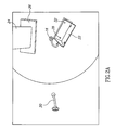
- Figs. 1A, 1B and 1C show respective top and side section views of a cavity 10, in accordance with an exemplary embodiment of the invention.
- Cavity 10 is a cylindrical cavity made of a conductor, for example a metal such as aluminum, and is resonant in the UHF or microwave range of frequencies, optionally between 300 MHz and 3 GHz, more preferably between 400 MHz and 1 GHZ.
- the cavity is a spherical, rectangular or elliptical cavity.
- the general methodology of the invention is not limited to any particular resonator cavity shape.
- feed antennas 16, 18 and 20 are positioned to feed energy at a frequency which is optionally chosen using the methods described below.
- Various types exemplary but not limiting antennae useful in carrying out the invention are shown in Figs. 4A-4C .
- one or more matching elements 22, 24 are placed inside the cavity, optionally near the feed antennas.
- Two types of field adjusting elements are shown, however, other shapes and materials can be used.
- First field adjusting element 22, shown more clearly in Fig. 2A is situated on end 12 of cavity 10.
- the element is rotatable about an axis 28 attached to the end, in a direction 30.
- it is insulated from the end by an insulating sheet 32 which couples element 22 capacitively to end 12.
- it is conductively attached.
- element 22 (as well as the other field adjusting element) has a dual effect, when properly adjusted. On the one hand it changes the modes of the cavity in a way that selectively directs the energy from the feeds into the object to be heated. A second and related effect is to simultaneously match at least one of the feeds and reduce coupling to the other feeds.
- Field Adjusting element 24, shown more clearly in Fig. 2B is situated between feed 18 and end 12.
- One end of the element optionally is electrically attached to cylindrical portion 14 of the cavity.
- the other end of element 24 is spaced and insulted from end 12 by insulating material 36. It is free to slide along end 12 and cylindrical portion as shown by arrows 33 and 34. This sliding changes the spectral variation of the energy absorption efficiency.
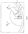
- Fig. 3 is a perspective drawing of the interior of the cavity to more clearly show the position and orientation of the feed and elements.
- Figs. 4A-4H show three different types of antennas that are useful in carrying out the invention. These antennas are either novel per se, or if known have never been used for feeds in a microwave oven or heater, especially in a cavity type heater. In general, in most microwave cavity type heaters, the feeds used are not directional to any great extent and not wideband, as defined in free air. The object of the feeds to excite the modes of the cavity. Since the cavities of the prior art are excited at a single frequency or a narrow band of frequencies, the antennas were designed specifically to excite these modes. In addition, prior art microwave cavities, use waveguides or loop antennas which are not designed to lower the coupling of energy from one feed to another (they generally have only a single feed). The present inventors have discovered that the use of directional antennae and/or wideband antennae allows for better coupling to the heated object and lower coupling to other feeds.
- the antennas are supplied as arrays. There are some advantages in using an antennas array.
- the band may be larger and there is a lower dependence of the heated object location on the results.
- the directivity may be controlled, even adjusted during heating. It is possible to control the phase of every single antenna of the array, controlling the RF mode. It is possible to alter the antenna structure, for example, using the helix antenna, the radius and the height of the antenna may be changed in order to tune the impedance and change the RF mode.
- Fig. 4A shows an antenna useful for coupling energy from feeds 16, 18 and 20 into cavity 10, in accordance with an embodiment of the invention.
- feed 16 includes a coaxial feed 37 with its center conductor 36 bent and extending into the cavity.
- the center conductor is bent but does not touch the walls of the cavity.
- the end of the wire is formed with a conductive element 40 to increase the antenna bandwidth.
- antennas of the type shown are able to couple energy better to an irregular object in the cavity. It is believed that such antennas transmit directionally and if the bend is aimed toward the object being heated, then coupling to the object (as opposed to coupling to the cavity) will be improved.
- Fig. 4B shows a helix antenna useful for coupling energy from feeds 16, 18 and 29 into cavity 10, in accordance with an embodiment of the invention.
- feed 16 include a coaxial feed 37 with its center conductor 36' having an extension that is formed into a helix.
- This antenna can be designed for matching into free space over a relatively wide band of frequencies (such as that useful for the present invention) and can be made more or less directional by changing the number of turns.
- the free space design is then adjusted for the presence of the cavity as described below with respect to Fig. 4C .
- the graph of Fig. 4C shows experimental results for a helix of 7 turns, with a diameter equal to the free space wavelength and a turn pitch of less than 0.2 wavelengths.
- the present inventors have found that curves of the type shown in Fig. 4C can be found, by experimentation, for other turn characteristics as well.
- Fractal antennas are known in the art. Reference is made to Xu Liang and Michael Yan Wan Chia, “Multiband Characteristics of Two Fractal Antennas,” John Wiley, MW and Optical Tech. Letters, Vol. 23, No. 4, pp 242-245, November 20, 1999 . Reference is also made to G.J. Walker and J.R. James, “Fractal Volume Antennas” Electronics Letters, Vol. 34, No. 16, pp 1536-1537, August 6, 1998 . These references are incorporated herein by reference.
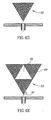
- Fig. 4D shows a simple bow-tie antenna 50 as known in the art, for radiation into free space.
- the Bandwidth of the bow-tie (in free space) is: 604MHz @ 740MHz center frequency (-3dB points) and 1917MHz @ 2.84GHz center frequency.
- This antenna has a monopole directivity pattern but a broadband one (being an advantage over the narrow BW of a dipole antenna).
- monopole directivity does not irradiate in a direction parallel to the feed.
- the band width (BW) of this antenna varies between 10MHz and maximum of 70MHz depends of the load (object) position inside the cavity.
- This and the following fractal antennas can be useful in the present invention to feed energy into a cavity.
- Fig. 4E shows a simple Sierpinski antenna 52, useful in the practice of the present invention.
- the cross-hatched areas 54 are metal plate and the white central area 56 is a non-conducting region.
- the metal plates are mounted on a preferably low dielectric constant dielectric and are connected at the corners and to center conductor 37 of coaxial feed 36, as shown. It's characteristics in the cavity are similar to those of the bow-tie antenna.
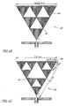
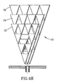
- Fig. 4F shows a modified Sierpinski antenna 58, useful in the practice of the present invention.
- the cross-hatched areas 60 are metal plate and the white areas 62 are non-conducting regions.
- the metal plates are mounted on a preferably low dielectric constant dielectric and are connected at the corners and to center conductor 37 of coaxial feed 36 as shown.
- the center frequency of this antenna is about 600 MHz inside the cavity.
- Fig. 4G shows yet another modified Sierpinski antenna 64, useful in the practice of the present invention.
- the cross-hatched areas 66 are metal plate and the white areas 68 are non-conducting regions.
- the metal plates are mounted on a preferably low dielectric constant dielectric and are connected at the corners and to center conductor 37 of coaxial feed 36.
- Fig. 4G Dimensions are shown on Fig. 4G for an antenna having a center frequency of 900 MHz in the cavity.
- Fig. 4H shows a multi-layer fractal antenna 70 made up of three fractal antennas spaced a small distance (e.g. 2 mm) from each other.
- each of these antennas is staggered in order to broaden the bandwidth of the antenna.
- a first antenna 72 is scaled to 0.8 of the dimensions given in Fig. 4G .
- a second antenna 744 has the same dimensions as the antenna of Fig. 4G and a third antenna 76 is increased in size over antenna 74 by a factor of 1.2.
- the volume fractal antenna ( fig. 4G ) has an overall bandwidth of 100MHz - this is an improvement over the 70 MHz maximum BW achieved in prior single fractal antenna ( figs. 4D-4H ).
- Fractal antennas also show a center frequency change when placed in a cavity. This difference is used (as with the helical antenna to design antennas for use in cavities by scaling the frequencies.
- antennas include patch antennas, fractal antennas, helix antennas, log-periodic antennas and spiral antennas.
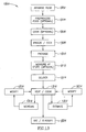
- Figs. 5A to 5D are schematic block diagrams of an electromagnetic heating system, in accordance with an embodiment of the invention.
- Fig. 5A shows a general block diagram of each of the power feeds 90 of the system, in an exemplary embodiment of the invention.
- the system is controlled by a computer 92 which via a control interface (Controller) 130 controls an RF system 96 which provides power to the heated object 98.
- Controller controls an RF system 96 which provides power to the heated object 98.
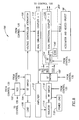
- Fig. 5B is a block diagram of the electronics of one of the RF feed systems 96, in accordance with an exemplary embodiment of the invention.
- a VCO 102 receives a signal from a control circuit 130 ( Fig. 5C ) which sets the frequency of the energy into the port. This energy is passed through an RF switch 104 and a voltage controlled attenuator (VCA) 106, both of which are controlled by control circuit 130. After passing through the VCA, the power and frequency of the signal have been set.
- a load 108 is provided for dumping the signal generated by VCO 102 when the signal from VCO 102 is not switched to the VCA.
- the signal is then sent through the main line of an optional first dual directional coupler 110.
- the output of the VCA is then amplified by a power amplifier 112 and after passing though an isolator 114. A signal proportional to the power reflected from amplifier 112 is also fed to the control circuit.
- Coupler 110 feeds back a portion of the signal entering it (after detection or measurement of power) to control circuit 130.
- a signal proportional to the power reflected by amplifier 112 is also sent to controller 130.
- An RF switch 116 switches the power either to a load 118 or to the feed of resonator 98, via a second dual directional coupler 120.
- Dual directional coupler 120 samples the power both into and out of the resonator and sends power measurement signals to controller 130.
- RF amplifier 112 is a solid state amplifier based on the LDMOS technology.
- Psat 300W
- Efficiency about 22%
- Effective band - 800-1000MHz Such amplifiers either have a relatively narrow bandwidth or a low efficiency ( ⁇ 25%) or both. This limits the optimal utility of the advances of the present invention.
- amplifiers have become available based on SiC (silicon carbide) or GaN (gallium nitride) semiconductor technology. Transistors utilizing such technologies are commercially available from companies, such as Eudyna, Nitronex and others.
- Amplifiers having a maximum power output of 300-600 W can be built from low power (50-100 Watt) modules) and a bandwidth of 600 MHz (at 700 MHz center frequency) or a bandwidth of 400 MHz (at 2.5 GHz center frequency are available, for example.
- Such amplifiers have a much higher efficiency than prior art amplifiers (efficiency of 60% is available) and much higher tolerance to reflected signals, such that isolator 114 can often be omitted for these amplifiers.
- a particular configuration utilizing this type of amplifier is described below in conjunction with Figs. 12A-D .
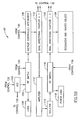
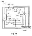
- controller 130 comprises computer 92 which performs computations and provides a logging function of the system as well as acting as a user interface. It also controls the rest of the elements in performing the calibration and control method of the flow charts of Fig. 7 .
- Computer 132 is coupled to the rest of the system through an interface 134 which is designed to provide communication to, for example, an ALTERA FPGA 140, which interfaces with and provides control signals to the various elements of the RF system.
- the Altera receives inputs (as described above with respect to Figs. 5A-5C ), via one or more multiplexers 136 and an A/D converter 138. In addition, it sets the frequency and power of each of the feeds (also described with respect to Figs. 5A and 5B ) via D/A converters 140 and the positions of the field adjusting element optionally utilizing the method described with aid of the following flow charts.
- the computer may not be necessary and the Altera or a similar controller may control and process all the necessary data.
- the frequency is swept as described below.
- Fig. 6 is a simplified flow chart 150 of the operation of a heating system having the structure described above.
- Fig. 7 is a simplified flow chart of calibration 160 of the system. As will be evident, the method operation and calibration of the system is also usable with only minor changes for operating systems with lesser or greater numbers of power feeds and/or a greater or less number of matching elements.
- an object for example a frozen organ or frozen or non-frozen food object
- a calibration or adjustment routine is then optionally performed to set the variable elements in the system. These can include power output of the amplifiers 112 in each of the power feeds to the cavity at each frequency, chosen to be transmitted, the finite set of sub-bands of frequencies of each VCO 102, the method of providing energy at the various frequencies (for example sweep or other frequency variation, or the provision of a pulsed signal embodying the desired frequency and power characteristics), positioning of the matching elements (e.g., 22, 24), position of the heated object and any other variables that affect the various characteristics of the heating process, for example - the uniformity and/or efficiency of power transfer to the object.
- a memory contains the criteria 156 for calibrating the system. Exemplary criteria are described below. Calibration is carried 160 out to determine the new heating variables.
- An exemplary calibration routine is outlined in the flow chart of Fig. 7 , discussed below.
- the new variables are set 158 and heating commences 170.
- the heating Periodically (for example a few times a second), the heating is interrupted for a short time (perhaps only a few milliseconds or tens of milliseconds) and it is determined 154, optionally based on a method described below, whether heating should be terminated. If it should, then heating ends 153. If the criterion or criteria for ending heating is not met, then the calibration (or re-adjustment) routine 160 is entered. If not, the heating 170 is resumed. It is noted that during the measurement phase, the sweep is generally much broader than during the heating phase.
- the power is optionally set at a level low enough 162 so that no substantial heating takes place, but high enough so that the signals generated can be reliably detected.
- calibration can take place at full or medium power. Calibration at near operational power levels can reduce the dynamic range of some components, such as the VCA, and reduce their cost.
- Each of the inputs is then swept 164 between a minimum and a maximum frequency for the channel.
- the upper and lower frequencies are 430 and 450 MHz.
- Other ranges, such as 860-900 MHz and 420-440 can also be used. It is believed that substantially any range between 300-1000 MHz or even up to 3 GHz is useful depending on the heating task being performed.
- the broadband, high efficiency amplifiers described above are used, much larger bandwidth of several hundred MHz or more can be swept, within the range of the amplifiers.
- the sweep may be over several non-contiguous bands, if more than one continuous band satisfies the criteria for use in heating.
- the present inventor has found that under many operating regimes it is desirable to maximize certain criteria.
- the maximum net power efficiency for each port is maximized, in the sense, that the net power efficiency at a point of maximum efficiency within the sweep range is made as high as possible.
- the efficiency and the frequency at which the efficiency is a maximum is noted.
- the width of the efficiency peak and a Q-factor are noted as well.
- a second embodiment of the invention is based on a similar criterion.
- the area under each resonance peak of the net efficiency of transfer is determined. This area should be a maximum.
- the efficiency, the center frequency of the resonance having the maximum area and its width are noted.
- the criteria for determining if the variables are properly set is when the peak net efficiency (first embodiment) or the area or a width (second embodiment) is above some predetermined level or a Q-factor is below some predetermined level. For example, there may be a restriction that the area above 60% net efficiency is maximized for each of the feeds.
- the frequency is swept, optionally while adjusting the power.
- the term swept should be understood to include serial transmission of individual non-contiguous frequencies, and transmission of synthesized pulses having the desired frequency/power spectral content.
- each frequency has maximal absorption at a specific location within an object within a cavity, which locations may vary between different frequencies. Therefore sweeping a range of frequencies may cause movement of the peak heating region within the object.
- Computer simulations have shown that, at least when the Q factor of a peak is low (i.e., a lot of energy is dissipated in the object being heated) the movement of the peak heating region can be quite substantial.
- each mode represented by a different peak of efficiency acts differently when swept.
- Fig. 11A is a simplified flow chart 200 of a method of determining swept power characteristics, in accordance with an embodiment of the invention. This method corresponds to acts 160 and 158 of the flow chart of Fig. 6 .
- the cavity After placing the object in the cavity (152) the cavity is swept to determine the input efficiency as a function of frequency (202) (e.g., obtain a spectral image). Determination of input efficiency is described in detail above.
- a pulse of energy, having a broad spectrum in the range of interest is fed into the input.
- the reflected energy and the energy transmitted to other inputs are determined and their spectrums are analyzed, for example using Fourier analysis.
- the net power efficiency as a function of frequency can be determined.
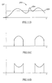
- Fig. 11B shows a simplified net power efficiency curve 250 at an input. It is noted that there are regions in which the efficiency is high and others in which the efficiency is low. Furthermore, some of the efficiency peaks are broader and others are narrower.
- the overall swept bandwidth (BW) is determined (204). This may include sweeping across a single peak or across several peaks.
- the frequency is swept across a portion of each of the high efficiency peaks.
- the power inputted to the cavity at each frequency should be the same.
- the power at each frequency is adjusted such that P* ⁇ ) is a constant for all the frequencies in the sweep. Since the power available is always limited to some value, this may set a limit on the available bandwidth for the sweep.
- An example of a lower limit to efficiency is shown as dashed line 252 in Fig. 11B .
- the sweep may be limited to frequencies having efficiency above this value.
- the positions of the field adjusting elements are set. This adjustment is optional and in some situations, even where such elements are present, they do not need to be adjusted.
- the criterion for such adjustment is that the peaks have as high efficiency as possible with as broad a peak as possible
- Specific applications may introduce additional goals, such as moving the peak to a certain band.
- An iterative process (206, 208) is used to determine a desired position and/or orientation of the field adjusting elements.
- the search process which may be any iteration process as known in the art, is completed the elements are set to the best position found. (210).
- the sweep is adjusted (212) to avoid feeding excess power into certain parts of the object.
- the object contains a metal rod or a metal zipper
- a high peak in efficiency 254 may be generated.
- a metal rod can cause a concentration of energy near the ends of the rod. Avoiding irradiation at this peak can sometimes reduce the effects of such objects on even heating.
- Fig. 11C shows the power spectrum 256 of energy to be fed to the input, in accordance with an embodiment of the invention. It should be noted that no energy is transmitted at the frequency characteristic of the rod and that for other frequencies for which the efficiency is above the minimum shown at 252 in Fig. 11B .
- the power has a shape that is such that the product of the efficiency ⁇ and the power fed is substantially constant.
- the energy is fed to the port in the form of a pulse rather than as swept energy.
- a pulse such as that shown in Fig. 11C is generated by a pulse synthesizer. This pulse is amplified and fed into the input. The pulse synthesizer would then replace VCO 102 ( Fig. 5B ). It is understood that the pulse synthesizer can also be programmed to produce a sweep for use in determining the frequency dependence of ⁇ (act 164 of Fig. 7 ).
- a search is performed for a position of the matching elements at which the net power efficiency at all of the feeds meets the criteria. This is indicated at boxes 214 and 216, which represent a search carried out by changing the positions and/or orientations of the matching elements. Standard search techniques can be used (iteration) or a neural network or other learning system can be used, especially if the same type of object is heated repeatedly, as is common for industrial uses.
- the power is raised to a level suitable for heating and optionally swept.
- the power into the respective amplifiers is optionally normalized to provide a same net power into the cavity (and therefore, into the object) for each port.
- the least efficient port determines the power to the object. While in prior art ovens, the user decides on the heating time, in some embodiments of the present invention the desired heating time can generally be predicted.
- power is fed to all of the feeds at the same time. This has the advantage that heating is faster. It has the disadvantage that three separate sets of circuitry are needed.
- the power is fed to the feeds seriatim, for short periods. Potentially, only a single set of most of the circuitry is needed, with a switch being used to transfer the power from feed to feed. However, for calibration, a method of measuring the power transmitted from port to port should be provided. This circuitry could also be used to match the feeds when power is not being fed to them.
- Fig. 8 A different type of circuitry for providing both the heating and calibration functionality, in accordance with an embodiment of the invention, is shown in Fig. 8 , corresponding to the circuitry of Fig. 5B .
- Fig. 8 is similar to Fig. 5B up to the output of RF switch 116. Following RF switch 116 a second RF switch 192 transfers the power delivered by amplifier to one of the feeds. Only circuitry 200 related to feed 2 is shown.
- Circuitry 200 operates in one of two modes.
- a signal from control 130 switches power from RF switch 192 to dual directional coupler 120, via an RF switch 194.
- the rest of the operation of the port is as described above.
- a passive mode the input to RF switch 194 does not receive power from amplifier 112.
- Switch 194 connects a load 190 to the input of dual directional coupler 120.
- load 190 absorbs power that is fed from the cavity into the feed.
- additional simplification of directional coupler 120 may be possible, replacing the dual directional coupler with a single directional coupler.
- switches 116 and 192 and optionally the local switches can be combined into a more complex switch network.
- RF switch 194 can be replaced by circulator such that power returned from the feed is always dumped in load 190.
- the frequency of the power fed to a port can be fed at the center frequency of the resonance mode that couples the highest net power, i.e., the point of maximum efficiency of energy transfer to the object being heated.
- the frequency can be swept across the width of the resonance or, more preferably along a portion of the width, for example between the -3 dB points of the power efficiency curve, or as described above with respect to Figs 11A-11C .
- the power is adjusted during this sweep so that the net input power remains constant or more nearly constant during the sweep. This can be accomplished by changing the power amplification of the power amplifier inversely to the power efficiency of the instantaneous frequency being fed.
- Fig. 9 shows a graph of frequency of a particular peak with time for a typical thawing process. This graph illustrates one method of using the changes in the properties of the object during a thawing process to determine when the process is complete.
- the ordinate of Fig. 9 is the frequency chosen as an input for one of the feeds.
- the abscissa is time.
- the ice in the object turns to water. Ice and water have different absorption for microwave or UHF energy, resulting in a different return loss and coupling as a function of frequency. Not only does this change the match, but at least after rematching by adjustment of the matching elements, the frequency of the absorption efficiency peak changes.
- point A some of the ice has started to change into water and the frequency of match changes.
- point B all of the ice has changed to water and the frequency of match stops changing.
- the point at which all of the ice is turned into water can be determined and the heating terminated, if only thawing is desired. It is noted that the frequency change during thawing is large, as described herein, compared to allowed frequency changes in the prior art.
- Heating methods and apparatus of the present invention which allow for both even heating and provide knowledge of the progress of the thawing, can result in much lower or even non-existent re-crystallization.
- Apparatus and method according to the present invention have been used to defrost a pig's liver, Sushi or Maki and to cook an egg in the shell.
- Table 1 Comparison of Inventive Method and Conventional Microwave- Cow Liver Measurement Inventive Method Conventional Microwave Initial Temperature -50°C -50°C Final Temperature after thawing 8°C to 10°C -2°C to 80°C Power 400 Watt 800 Watt Thawing time 2 Minutes 4 Minutes Visible damage None The texture of the thawed sample was destroyed. There are frozen regions along side burned ones. No chance of survival of living cells.
- Table 2 shows a comparison between thawing of Maki containing raw fish covered by rice and wrapped in seaweed, by the system of the present invention and using a conventional microwave oven.
- Table 2 Comparison of Inventive Method and Conventional Microwave-Maki Measurement Inventive Method Conventional Microwave Initial Temperature -80°C -80°C Final Temperature after thawing 2°C to 6°C -5°C to 60°C Power 400 Watt 800 Watt Thawing time 40 Seconds 1 Minute Visible damage None The thawing process cooked part of the salmon, therefore it was not Maki anymore.
- An egg was cooked using the present method. Generally, eggs burst if an attempt is made to cook them in a microwave oven. However, using the system described above an egg in the shell was cooked. The white and yellow were both well cooked, and the white was not harder than the yellow. Neither part was dried out or rubbery and the taste was very good, with little if any difference from a conventional hard cooked egg. In addition, deep frozen fish have been defrosted without leaving any frozen portions and without any portions being heated above cooking temperatures.
- Thawing objects such as meat and fish with such low differences and at high speed has the potential for prevention of development of salmonella, botulism and other food poisons. Controlled, uniform thawing has important implications in thawing organs for transplanting, without tissue destruction.
- Fig. 10 shows apparatus for applying a DC or relatively low frequency (up to 100 kHz or 100 MHz) to an object in the cavity, in accordance with an embodiment of the invention.
- This figure is similar to Fig. 1 , except that the cavity includes two plates 250 and 252.
- a power supply (not shown) electrifies the plates with a high differential voltage at DC or relatively low frequency.
- the objective of this low frequency field is to reduce the rotation of the water molecules. Ice is water in a solid state therefore its rotational modes are restricted. A goal is to restrict the rotational modes of the liquid water in order to make the heating rate be determined by that of the ice.
- the present inventors also believe that the low frequency fields may change the dielectric constant of the materials making up the object being heated, allowing for better match of the input to the object.
- a DC or low frequency magnetic field is applied by placing one or more coils inside or preferably outside the cavity to cause alignment of the molecules in the object. It is possible to combine low frequency or DC electric and low frequency or DC magnetic fields with possible different phases from different directions.
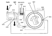
- Fig. 12A shows a cavity 98 with an internal heater coil 600 placed inside the cavity.
- An inlet 602 and an outlet 604 allow for feeding a hot fluid through the coil to heat the air within the cavity.
- Figs 12B and 12C show two schematic illustrations of a system for transferring heat from a high power amplifier 606 to the coil. Even at an efficiency of 60%, the amplifier can generate several hundred watts. This energy (or at least a part of it) can be transferred to heat the air and to produce infrared radiation (as a resistive coil does) in the cavity to increase the efficiency of heating.
- Fig. 12B shows a very schematic diagram to illustrate how waste heat from an amplifier 606 can be captured.
- Fig. 12C shows a block diagram of the same system.
- Element 608 represents a cooling system for returning fluid and a fluid pumping system. It receives return fluid from outlet 604, cools the liquid (if necessary) and pumps the liquid into a gap 610 between the between amplifier 606 and an optional heat sink 612. The temperature at the input to the gap and at its output are preferably measured by sensors 614 and 616 and fed to a control system 618, which controls one and optionally more than one of the cooling and pumping rate to provide a desired heat transfer to the cavity.
- a fan 620 may be provided to cool the heat sink as necessary.
- the fluid passing between the amplifier and the heat sink also functions to transfer heat from the amplifier and the heat sink.
- heat conducting rigs may transfer heat between the amplifier and the heat sink with the fluid passing between the ribs to collect heat.
- heat pipes or other means can be used to collect and transfer energy to the cavity.
- hot air could be passed over the amplifier and/or heat sink and passed into the cavity.
- a heater as shown in Fig. 12D including a housing 650, amplifiers and controller, as well as a user interface 652 and a door 654, as normally found on a microwave oven can weigh as little as 10 or 15 Kg or less.
- UHF frequencies are absorbed preferentially by ice and have a longer wavelength than the higher frequencies, so that the fields within the object are more uniform and the ice is preferentially heated as compared to the water. This provides for preferential heating of the ice and more even thawing.
- the wrapping can include identification of the object to help track the object and also to provide an indication to the system of a preferred protocol for heating the object.
- the wrapping may be provided with a number of resonant elements which can be detected when the cavity is swept during calibration. The frequencies of the elements can be used to provide an indication of the identity of the object. This allows for the automatic or semi-automatic setting of the starting parameters for calibration and/or for a particular heating protocol, optimized for the particular object and conditions.
- a recording/storage element of a different type is provided, for example, in the form of an RFID element or a bar-code, which includes thereon an indication of the content of a package or wrapper including the object, suggested treatment thereof and/or heating instructions.
- the instructions are actually provided at a remote site, indexed to a key stored by the recording element. Such instructions may be, for example, stored in a table or generated according to a request, based on information associated with the identification.
- a reader is optionally provided in the heater, for example, an RFID reader or a bar-code reader to read information off a package or a wrapper thereof.
- various types of information are optionally stored on (or in association with) the recording element, for example, size, weight, type of packing and/or cooking/thawing/heating instructions.
- the recording element has stored therewith specific cooking instructions.
- the recording element has stored therein information regarding the platter shape and/or dielectric properties of its contents. It is noted that for industrial shaped portions, if the shape of the food is relatively regular between platters, movement of the food and/or changes in size and/or small changes in shape will not generally affect the uniformity by too much, for example, shifting a heating region/boundary by 1-2 cm.
- the platter includes a depression and/or other geometrical structures which urge the food item to maintain a desired position relative to the platter borders.
- the parameters of the heating are optionally varied.
- the effect of the varying may cause non-uniformity in space and/or in time.
- a script is provided which defines how and what to vary.
- the script includes decisions made according to time (e.g., estimation of an effect) and/or food state (e.g., measurement). Various measuring methods are described above. Estimation is optionally based on a simulation or on empirical results from previous heating cycles.
- the script is conditional (e.g., modified, generated and/or selected), for example, based on the position of a platter in the oven and/or personal preferences (which may be stored by the oven).
- a script is provided on the recording element or at a remote location.
- a script is selected by a user selecting a desired heating effect.
- a single food item may experience different power levels for different times, in order to achieve a desired texture/flavor.
- a script is used to set different energy levels and/or different times to apply such energies.
- a script is as follows:
- the script includes other conditions, for example, detecting changes in color (e.g., browning), steaming (e.g., by phase change of water), volume (e.g., dough rising will change the behavior of the cavity in ways that can be anticipated).
- changes in color e.g., browning
- steaming e.g., by phase change of water
- volume e.g., dough rising will change the behavior of the cavity in ways that can be anticipated.
- the script includes a request to the user to add ingredients (e.g., spices), or to mix or reposition object.
- ingredients e.g., spices
- the script takes into account the quality of uniformity control achievable by the oven. For example, if a higher level of uniformity is desired than basically provided by the oven, heating may include pauses where power is reduced, to allow heat to even out in the object. The length of the delays is optionally pre-calculated for the food substances and a calibrated lack of uniformity of the oven. Alternatively or additionally to reducing power, the food and/or the heating areas may be moved one relative to the other so as to better distribute heating.
- no script is provided. Instead, the heating times and/or parameters are based directly on the desired results, measured food properties and/or measured heating properties. Such desired results may be user provided or indicated by the recordable element.
- the present invention has been described partly in the context of thawing.
- the inventors believe that based on the results shown above, it can be expected that the methods of the present invention, can be used for baking and cooking, areas in which conventional microwave ovens are notoriously weak or for other heating operations, especially those for which a high level of uniformity or control is needed and/or in which a phase change takes place.
- the UHF or microwave energy may be deposited uniformly in an object to within less than ⁇ 10%, ⁇ 20% or ⁇ 30% over 80% or 90% or more of the object.
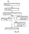
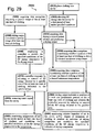
- Fig. 13 is a flowchart of an exemplary process 1300 of food preparation in accordance with exemplary embodiments of the invention. After a brief review of the flowchart, each act will be expanded on. It should be appreciated that the order of acts may be varied and that several of the acts shown are optional.
- the process shown includes food preparation, storage and consumption, generally at a remote location. In some cases, only the preparation and/or consumption portions of the process are carried out.
- the food is arranged for processing, for example, being cut to size.
- the food is optionally pre-processed, for example, a surface thereof dried (e.g., air-dried) or spices added.
- the food is optionally cooked.
- food is processed during cooking, for example, spices added.
- the food is cooled, frozen, canned and/or otherwise prepared for storage.
- the food is packaged.
- the packaging is optionally selected to match the food shape and/or reheating process. In some cases, the food is packaged at an earlier stage.
- one or more properties of the food are optionally measured. Such measurements may be stored for example, on the package or at a central location.
- the food is delivered, for example, to stores and/or restaurants.
- the food is heated, for example, for thawing or cooking.
- various properties of the heating/food e.g. a spectral image, e.g., a scan of the dissipation of RF energy at different frequencies
- a spectral image e.g., a scan of the dissipation of RF energy at different frequencies
- one or more properties of the heating/food are estimated (1322) and the heating parameters are modified (1324).
- the modification may be, for example, spatial (e.g. moving patches and or the heated object and/or changing the frequencies), and/or heating profile (i.e. the frequencies transmitted and the matching powers) (e.g., a time/frequency/power triplet).
- the movement of the object affects the spectral image (e.g. the absorption in each frequency).
- the triplet defines the transmission selected. For each frequency there is a time of transmission and a power of transmission (thereby generating the triplet). The longer the heater transmits in a given frequency at a given power, the more energy is dissipated in the object. Movement may affect the decision of whether or not to transmit at a given frequency, at what power and for how long. IT should be noted that in some embodiments of the invention, location/movement are not "measured" directly, but often affect the spectral image. It is noted that the total absorbed power may be estimated using methods as described herein.
- the food is optionally consumed and/or classified for consumption according to the quality of the food preparation and/or storage.
- the following discussion is loosely based on two examples, one of preparation of food portions, in which multiple food items are provided on a single platter and one of industrial preparation of food, such as a fish.
- Other examples include, omelet, rice, meat, cake, fresh fruit or vegetables, salad, dairy products, seasonal products, short shelf life products, medicine and/or food additives.
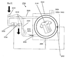
- Fig. 14 is a schematic cross-sectional view of an RF heater 1400, in accordance with an exemplary embodiment of the invention.
- This heater may be used, for example, for cooking/heating/thawing, including 1306 and 1316 of Fig. 13 .
- Heater 1400 generally follows the description of Figs. 1-10 , showing radiator antennas 16, 18 and 20 and field adjusting elements 22/24.
- RF system 96 and computer/controller 130/92 as described above may be used, optionally with different programming as described below.
- the cavity may be rectangular or have another form.
- the controller may contain an ASIC and optionally include an ability to execute RF simulations.
- Other implementation methods, including software, firmware and hardware may be used.
- the controller includes one or more tables of desirable settings to use under various input conditions to achieve desired outputs.
- Such tables may be generated/calibrated on an individual device basis or for a plurality of optionally similar devices. Variations of the above design may be provided as well. Some embodiments of the invention may be practiced, possibly with reduced quality, using a standard microwave oven. The following elements are described briefly and then again as part of the exemplary food preparation process.
- the oscillators for sweeping and for heating are different, for example, using a VCO for sweeping, optionally with periodic calibration and a stable oscillator for heating.
- a VCO for sweeping
- periodic calibration for a stable oscillator for heating.
- a stable oscillator for heating is described in US Provisional Patent Application No. 60/924,555 filed 21 May 2007 for ELECTROMAGNETIC HEATING, the disclosure of which is incorporated herein by reference.
- An optional imager 1402 for example an X-Ray imager, a millimeter wave imager or CCD is used to obtain an image, optionally including water concentrations and/or dielectric properties of a food item placed on a tray 1406.
- Tray 1406 optionally has one or more guide elements 1408 to ensure correct placement of food (especially food provided in suitably designed packages) thereon.
- the oven is programmed or programmable to act differently for certain package designs.
- Tray 1406 is optionally mobile, for example, using an actuator (not shown).
- a reader 1404 is optionally provided, for example, an RFID reader or a bar-code reader to read information off a package.
- the reading is done by same sensor as used for the sweeping, possibly at a different frequency. It is noted that even if the heating antenna are optimized for a certain frequency range, they ca still operate at other ranges, harmonic or not.
- the information read off the package may, in some embodiments, include instructions regarding the desired taste, texture and/or other effect of the food preparation (e.g. browning, whether a steak should be raw or well done, etc.).
- a steak package may include at least two distinct operation instructions - well done but less crispy or medium and more crispy.
- the oven may prompt the user to select between the modes. Each mode dictates, for example, what power level(s) to use at what frequency and when, whether or not to provide power that would dissipate in a crisping element and how much and when to provide same.
- the oven might be sensitive to the power absorbed in the object or a portion thereof, and upon achieving a pre-determined change, the change is detected by the oven and the oven can react and change the heating mode
- the package can include a liquid that expands during heating. As the cooking progresses the steam created by the liquid opens the package, and the device detects the change in the spectral image (due to the phase change of water), which can be used to decide to turn on a browning mode.
- a packaging site take away at a restaurant or industrial facility
- may use different packages, each with distinct instructions for heating modes e.g. fast and less uniform or vice versa).
- a user may purchase packed food that would heat at the user's preferred heating rate (rather than only the desired cooking effect).
- one or more sensors 1410 read a size, weight and/or machine readable information of a package, once the package is placed on the tray.
- a user enters the information, for example, into a keypad of an RF oven or using an external bar-code reader.
- a radiation blocking baffle 1412 is provided which can be selectively positioned (e.g., 1414) to block radiation from food on tray 1406. While a rotary hinge activated by an actuator 1416 is shown, other designs may be used, for example, baffles which come from two or more sides of the food, and sliding baffles.
- one or more environmental control elements 1420 are provided, which may be used, for example, to control ambient temperature, air turbulence, humidity and/or pressure.
- the one or more environmental control elements 1420 include a UV lamp.
- the UV lamp is used to reduce contamination and/or bacterial growth during a keep warm operation or other long-term operations.
- an environmental sensor 1422 is provided to assist in closing a feedback loop on the environment.
- the RF absorption spectra indicate one or more environmental conditions, such as humidity level. In some cases, heating is modified to take into account existing environmental conditions.
- one or more conventional heating modules 1424 are provided, for example, an IR heater or a steam source.
- the heater may be configured to maintain food at about a given temperature (e.g. about a given temperature or within a predetermined zone such as 40-45°C).
- a dedicated heater capable of substantially only maintaining temperature is provided.
- a heater can be set to a mode where any opening and closing of its door (if any) cause the device to automatically attempt to heat/cool an object therein (optionally only if the presence of an object is detected, e.g. by a frequency scan or weight detection) to the target temperature. Maintaining a temperature may be useful, for example, in restaurants, where a dish is maintained at a temperature suitable for serving, but desirably without damaging of the dish and/or allowing growth of pathogenic microbes.
- the heater may include one or more cooling elements (e.g., refrigerator coils or a cool air source) for reducing temperatures.
- a "keep warm” mode may be provided in various manners, including:
- the heater includes one or more radiation sensors which detect energy/heat emission during cooling and the controller controls the heater to input the same missing energy upon demand. Temperature measurement may be, for example, in the heater chamber, on the plate, or by sensing the food itself (e.g. IR sensor or optical fiber).
- the reheating on demand uses a suitable power so that heating time is very short, for example, less than 1 minute, less than 30 seconds, less than 10 seconds or less than 3 seconds (e.g., if sufficient power si provided for the food size, for example, 27KW for 300gr of meat.
- an optimized starting configuration is determined during a prior heating step, so that reheating can proceed faster and with greater assurance.
- a fast scanning is carried out (e.g., 3-4msec.
- 3-4msec For example, if an object is to be thawed in 20 seconds significant changes in the spectral image could be detectable in about 2 seconds.
- 10 sweeps/second are carried out, which slow down the thawing by about 1.5% of the time. Fewer sweeps can be carried out, for example 2 sweeps/sec. It should be noted however, that if the heating includes adjusting patches, each adjustment typically requires a repeated sweep before heating begins and takes time to perform.
- a package that details the starting conditions/configuration and the maximal bandwidth that may be reached by moving the patches (e.g., a best achievable result).
- the package includes an average convergence time (or other statistic of the simulation). A significant deviation from the average can indicate that there might be a problem with the package and/or the heater.
- the heater uses the best result that was found even if it is not nearly as good as the expected result.
- the heater may report a problem (e.g., to user or via network).
- the package information is used to reduce the number of sweeps. For example, if one heater repeats the sweep 15 times and averages the results, having "original" sweep results can allow the number of sweeps to be reduced (e.g., only to find a deviation), thus allowing a single sweep to be shorter than 1 msec, for example, 10s or 100s of microseconds.
- the user interface of an oven according to the present invention may be reduced and/or simplified to improve the ease of operation.
- An oven may be for example dedicated to reach a desired final temperature (e.g. refrigeration temperature 4-8°C or room temperature (20-25°C) or any other temperature (e.g. 50-65°C, etc.).
- a desired final temperature e.g. refrigeration temperature 4-8°C or room temperature (20-25°C) or any other temperature (e.g. 50-65°C, etc.).
- the oven has several final temperatures (e.g., 5-10 options each defining a temperature range of 4-10°C, covering a range between 0 and 100°C) and the user may choose the final temperature.
- the options may be limited to partially thaw (-5-0°C), thaw (4-8°C), room temperature (20-25°C), warm (40-50°C), hot (60-70°C) and very hot (90-100°C).
- the heater has a mode that prevents unauthorized users (e.g. children) from reaching a temperature that is considered less safe (e.g. 35-40°C or more or 45-50°C or more).
- a similar feature may be provided to prevent damage to food or packaging or prevent fires (e.g., based on temperature or energy absorption).
- the temperature is optionally provided on a package or pre-stored in the heater. One setting may be pre-set to override the other.
- the limiting feature is applied by requiring a special code for any step including a temperature above the limit.
- the heater door may be locked such that it would not open as long as the object temperature is higher than the safe temperature, unless a user override (e.g.
- the oven supports an option of choosing a desired rate of heating which would cause the oven to either use more power or be less uniform.
- the oven is capable of automatically calculating a proper operation mode, regardless of food shape/ size/ composition/ geographic location, using for example the frequency sweep method described herein and/or using a temperature sensor, thereby supporting simplification of the interface.
- the food is shaped and/or arranged in a manner which matches the intended processing steps.
- food may be arranged to have (relatively) uniform weight, thickness and/or shape.
- the different foods are optionally each arranged in a predetermined compartment of a platter.
- a food item is provided which affects the later processing, for example, a layer of fat or of ice may be used to later baste and/or shield a part of the food.
- a note is taken of the food freshness and/or other properties thereof.
- the selection takes into account planned processing steps.
- the processing is modified to take the food properties into account. For example, different thawing instructions may be provided for overripe and under ripe fruit or for old fruit.
- the food is pre-processed, for example, injecting water, injecting fat, adding spices or other flavoring agents and/or preservatives, adding cryogenic agents which affect the freezing process (such as alcohol), blanching, pasteurizing or enzyme deactivation (e.g., using a uniform field as described below), washing, sterilization and/or drying out of an outside layer (e.g., to reduce microwave radiation absorption at this layer and/or enhance flavor absorption), optionally using a uniform field which is limited to the layer and does not significantly extend into the food item.
- the food is pre-processed before arrangement and/or pre-processed both before and after arrangement, possibly applying different pre-processing types.
- one or more agents are injected to improve heating process characteristics, such as by lowering Q factor, improving absorption (for example by adding salt, such as in kosher products), improve composition homogeneity and others.
- Other pre-processes may be selected in order to improve the spectral image (e.g. lower Q factor), as well, for example, immersion in an RF absorbing liquid.
- part of the object e.g., its surface
- the surface is made more moist or more dry than the rest of the object such that during heating it will (or will not) dry and become more crispy or browned.
- Some types of food are cooked or partially cooked before delivery. Any known method of cooking may be applied, including heating in a relatively uniform manner as described above. In some cases, the food is at least partially packaged before being cooked.
- the food (cooked or otherwise) is cooled or frozen, or otherwise prepared for storage, for example, by canning (where uniform microwave heating may be applied for non-metallic packages).
- cooling uses controlled directional cooling, for example, using a temperature gradient as described in US patent 5,873,254 and PCT publications WO 2006/016372 and WO2003/056919 to applicant IMT, the disclosures of which are incorporated herein by reference, or by uniformly heating a part of the food using microwave energy while cooling the food, and changing the heated part (relative to the food item) so that a freezing front propagates in a controlled manner.
- the freezing is controlled to prevent damage to the texture of the food. It is noted that the feedback from microwave heating signals can be used to determine the state of freezing of a food sample, for example, by detecting dielectric property changes associated with phase and/or temperature changes.
- the food may be packaged at an earlier stage, for example, before cooking.
- the packaging is selected to assist in later spatially controlled microwave heating.
- Fig. 15 illustrates an exemplary food platter 1500 for use in packaging in accordance with exemplary embodiments of the invention (e.g. in a microwave oven and/or RF heater).
- a body 1502 for example of molded plastic defines one, two or more compartments 1506 and 1510, in which foodstuffs, for example different foodstuffs 1504 and 1508 are provided.
- platter 1500 is designed to assist in non-uniform heating of food (e.g. so that at least one food item is heated differently from at least one other food item or that a certain food is heated in layers).
- the RF is emitted into cavity is uniformly and one or more techniques are used to vary the uniformity of energy absorbed by food. Methods that relate to utilizing packaging for controlling non-uniformity are described following.
- a microwave absorbing element 1512 is provided on one or more sides of a food compartment, changing the amount of energy entering into a portion of the compartment to heat food therein.
- energy absorbing and/or reflecting element 1512 is used to scorch/burn a pattern on the food when warmed (e.g., in the form of a grilling mesh on a meat dish).
- the oven may select one or more times during heating wherein the frequencies that interact with element 1512 are transmitted (or are not transmitted), thereby defining when the effect of this element will, or will not, take place.
- a radiation absorbing and phase changing element 1514 which changes its radiation absorption as it heats, thereby temporally modifying the radiation entering a nearby compartment.
- the material may be set to melt at a certain desired temperature.
- the change in absorption is noted by a feedback system of the oven and used to detect temperature changes in the food.
- heating of element 1514 is used to provide radiative or contact heating of a nearby foodstuff 1504. Multiple elements 1514, each with different phase change temperatures may be provided.
- Element 1514 may be a passive source (e.g. an organized structure with a predetermined frequency response, such as dipole).
- passive sources optionally completely non-emitting) are provided which are selectively activated by selectively applying or not applying frequencies to which these sources react.
- One or more microwave transponders 1520 are optionally provided which generate a coded interference with the microwave in the cavity.
- interference with the microwave cavity behavior can be detected by analyzing the resonant properties of the cavity.
- the coding may be used to determine the relative amplitude of the field at each point along the platter, thereby assisting in matching the modes of the microwave cavity to the placement of food therein.
- the interference element is an active element that includes a receiving element, a modulator and a transmitting element, for example a frequency doubling element may be used.
- a non-RF transponder may be provided, for example, an ultrasonic transponder.
- One or more temperature sensors 1516 are optionally provided.
- the sensors generate a signal or interference with the field, for example, until a critical temperature is reached, at which time a part of the sensor melts or otherwise changes its electrical behavior (e.g. using a resonant structure that has a specific absorption profile. If the structure melts, its absorption pattern is no longer detected).
- an RF responding temperature sensor is provided.
- a more complex transponder element may include a temperature senor that modifies the modulation according to the temperature.
- the oven is designed to work with a TTT (temperature sensitive/transmitting tag), as described above.
- TTT temperature sensitive/transmitting tag
- the oven is optionally designed and/or controlled to avoid transmission at the frequencies used by the TTT.
- a bar-code that darkens (at least in part) as a temperature is achieved or a material that changes color as a temperature is reached, for example, liquid crystals.
- multiple temperature indicators are provided on the package, thereby giving an indication of uniformity of heating.
- an imaging sensor is provided below the tray, to image temperature on the bottom of the tray, where contact between the food and packaging is better guaranteed. Such sensors are optionally used to provide feedback on actual cooking conditions as exhibited by the food.
- a recording element 1518 is provided, for example, in the form of an RFID element or a bar-code, which includes thereon an indication of the content of the package, suggested treatment thereof and/or heating instructions.
- the instructions are actually provided at a remote site, indexed to a key stored on element 1518.
- various types of information are optionally stored on element 1518, for example, size, weight, type of packing and/or cooking/thawing/heating instructions.
- measuring includes radar, ultrasound or RF imaging which indicates shape uniformity and/or amount of water.
- measuring is performed before sealing the packaging.
- the information is not directly stored on element 1518.
- an index is read which is used to access remotely stored information.
- an oven is configured as a condition recorder.
- a user may put an object in the oven (condition recorder).
- the oven will measure a few characteristics (e.g. RF response (dielectric function), weight, color and/or the volume or any other characteristic) and provide a record of the object (e.g. stored in the oven, sent over a network and/or printed out as a sticker or tag or programmed into a programmable tag).
- RF response dielectric function
- weight e.g. stored in the oven, sent over a network and/or printed out as a sticker or tag or programmed into a programmable tag.
- the oven may measure the object again and provide a comparison between the first and second sets of measurements. This comparison may indicate a condition of the sample, for example, dehydration.
- a first device is used for the first measurement and a tag is issued with that data (e.g. at a site of production) and later (e.g., at a site of consumption) a second oven reads the tag and confirms quality unchanged. If a single oven is used, a user may indicate the identity of the object to the oven (e.g., before and after storage).
- An example of unwanted change is that if meat is stored in bad condition it may lose color (scanning can include a CCD or other image) and/or water.
- the changes indicate normally that the food was not stored properly.
- wanted change are ripening of fruit and rising of dough (e.g., if dough is left in the oven while rising, even if the oven only scans the dough). It should be noted that such scanning can be done independent of cooking, for example, purchased food can be scanned it to define an initial vale, and then again , before use scanning may be used to detect damage that might have occurred during storage at home, or possibly even the time that lapsed.
- a table for expected spectral changes for various items is stored in the heater/scanner, for example, changes due to water loss, ripening or decomposition.
- an element like element 1518 is used for non-platter items, for example, for frozen fish, for example, in the form of a tag.
- food is delivered to a restaurant on demand based on orders placed the night before.
- the food is prepared according to individual preference and/or diet restrictions.
- the preparation instructions associated with element 1518 are modified to match personal preferences.
- the modification is at order time.
- the modification is when a user actually comes to collect food.
- food is made ready at a time a person orders the food.
- delivery is to a supermarket or to users at home.
- delivery is to an automated vending machine which optionally includes a controllably uniform/non-uniform heater as described herein for heating/cooking the food.
- a vending machine includes one or more storage compartments (e.g., refrigerator and/or freezer) and one or more heating compartments (optionally continuous with storage).
- storage compartments e.g., refrigerator and/or freezer
- heating compartments optionally continuous with storage.
- the vending machine transfers the food (one or more types) to a heating portion and thaws/warms/heats the food, according to user or oven instructions (optionally based on a tag attached to the food.
- a plurality of food-stuffs are heated and served together, for example, on a same platter, to the same or to different temperatures.
- the food is made ready fast, for example, in a minute or less.
- heating uses the methods described herein so there is less dependence on portion size, composition and/or position, in achieving edible results.
- the food is prepared on premises for a large feeding organization, for example, a restaurant or employee meal plan.
- controllably uniform/non-uniform heating method described above is used to heat and/or cook the food.
- reader 1404 of heater 1400 is used to read element 1518 and determine a desired cooking/heating setting and/or more complex configuration.
- element 1518 has stored thereon specific cooking instructions (e.g. the amount of power that is to be absorbed in the food within a given period of time, and potentially also changes in the rate of energy absorption).
- element 1518 has stored therein information regarding the platter shape and/or dielectric properties of its contents. It is noted that for industrial shaped portions, if the shape of the food is relatively regular between platters, movement of the food around the effective heating area of the oven and/or changes in size and/or small changes in shape will not generally affect the uniformity by too much, since a similar spectral image would be read and the device may automatically compensate for the minor changes.
- the platter includes a depression and/or other geometrical structures which urge the food item to maintain a desired position relative to the platter borders.
- some of the methods of the present invention operate by providing a uniform heating area in the oven and modifying the effect of this region on food.
- a non-uniform heating region is generated and/or non-uniform areas are used.
- one or more of the following methods is used to provide uniform and/or non-uniform heating:
- a device may include a memory capable of storing a desired heating protocol or a desired heating result to match a patron's (or user's) preferences.
- the protocol is stored in the device either manually or automatically during use, and is optionally proposed as a default protocol on later use by the same patron (and/or of a same dish).
- the preferences are determined automatically, based on a history of past requests on a same or different heating device (e.g. in a vending machine from a chain of vending machines).
- the user is identified by code, cellular telephone number, social security number and/or a credit card code.
- the credit card is read during payment/ordering and used to set preferences.
- the amount of energy applied to a meal is adjusted according to the expected scheduling of the preparation of the meal.
- the scheduling takes into account the desires of multiple patrons, for example, tens or hundreds or thousands or more, all of which come for a meal at approximately the same time (e.g., "lunch hour").
- Such scheduling may also take into account, for example, the number of available ovens and/or the desirability for a group of patrons to be served at a same time.
- a central (or other) controller which controls a plurality of heaters and assigns tasks for enhancing performance. For example, each heater is assigned a different task (e.g. one prepares meat for several patrons in one batch or in sequence and another machine prepares the greens) so the heaters optimally or near optimally utilize available hardware, for example, to reduce time and/or to improve food delivery timing (parts of a dish should desirably all be ready at a same time, even if heater can "keep warm").
- a request for a meal arrives, one or more heaters is assigned to the meal, ad hoc.
- this method is used for patrons numbering, for example, between 2 and 10, between 11 and 40, between 40 and 100 or between 100 and 1000 or more.
- the controller of the plurality of heaters also controls one or both of a human scheduling system (e.g., which instructions are provided to which worker) and/or controls one or more food moving systems (e.g., conveyer belts).
- the parameters of the heating are optionally varied.
- the effect of the varying may cause non-uniformity in space and/or in time, for example, as will be described below and/or to achieve the effects as described above.
- a script is provided which defines how and what to vary.
- the script includes decisions made according to time (e.g., estimation of an effect) and/or food state (e.g., measurement). Various measuring methods are described above. Estimation is optionally based on a simulation or on empirical results from previous heating cycles.
- the script is conditional (e.g., modified, generated and/or selected) on the position of the platter in the oven and/or personal preferences (which may be stored by the oven).
- a script is provided on element 1518 or at a remote location.
- a script is selected by a user selecting a desired heating effect. The combination of the desired heating effect and the identification of the food/layout may cause the selection and/or generation of a suitable script.
- a desired heating program may set target amounts of energy for different parts of a platter and/or of a single food items and/or may set desired target temperatures. For example, a meat item may be heated to one temperature, while a side order is heated to a lower temperature. In another example, a single food item may experience different power levels for different times, in order to achieve a desired texture/flavor.
- a script is used to set different energy levels and/or different times to apply such energies.
- a script is as follows:
- the script includes other conditions, for example, detecting changes in color (e.g., browning), steaming (e.g., by phase change of water), volume (e.g., dough rising will change the behavior of the cavity in ways that can be anticipated).
- changes in color e.g., browning
- steaming e.g., by phase change of water
- volume e.g., dough rising will change the behavior of the cavity in ways that can be anticipated.
- the script includes a request to the user to add ingredients (e.g., spices), or to mix or reposition package.
- ingredients e.g., spices
- the script takes into account the quality of uniformity control achievable by the oven. For example, if a higher level of uniformity is desired than basically provided by the specific oven, heating may include pauses where power is reduced, to allow heat to even out in the object. The length of the delays is optionally pre-calculated for the food substances and a calibrated lack of uniformity of the oven. Alternatively or additionally to reducing power, the food may be moved relative to the cavity and/or heating or field shaping elements so to improve heating.
- a script for preparing a frozen food product until ready for consumption e.g. a product comprising frozen and viable yeast dough
- a product comprising frozen and viable yeast dough is as follows:
- the above script may be embodied, for example, in a bread making machine, into which frozen ingredients are placed, optionally into an insulated compartment, whereafter the ingredients are thawed, mixed, proofed and/or baked using methods as described herein.
- one or more steps of the above process include controlling the humidity within the oven (optionally maintaining high humidity during proofing and/or warming and/or storage and maintaining low humidity and/or high humidity during baking).
- the device may maintain a different humidity at different portions of the same step (e.g. high humidity during early baking a low humidity when IR is introduced). Additional details re humidity control are provided below under the heading "Environmental Control".
- different portions of the food may have different (desired or specified) absorbed power levels. Alternatively or additionally, different portions may have different target temperatures.
- spatial control is used to achieve selective browning (or other behavior) of a part of a food item, by applying a field which overlap mainly with an outer layer of the food, so that that layer is preferentially heated as compared to the rest of the food item.
- a bottom of a food item is made harder, by applying more heat, than an upper part of the food item.
- the entire outside of an item may be preferentially treated.
- the areas with preferential heating have a smallest dimension of 5 cm, 4 cm, 3 cm, 2cm or less.
- a user and/or platter specify what a desired spatial and/or temporal heating profile is and the oven determines a suitable set of instructions (e.g., spatial and/or temporal profile).
- a best-fit type algorithm is used to select heating ability elements and build a heating program that matches desires.
- Exemplary heating ability elements optionally used in such a search/construction include, uniform heating methods, baffle movements, platter movements and/or non-uniform heating modes or frequency possibilities.
- the heating times and/or parameters are based directly on the desired results, measured food properties and/or measured heating properties.
- a heater controller controls not only energy provision but also one or more environmental variables that affect food preparation.
- the environmental control is applied to achieve a desired cooking result, for example, reducing humidity to enhance crust formation.
- environmental control is applied to maintain environmental conditions, for example humidity.
- environmental control is applied to compensate for heating effects. For example, humidity may be increased if the heated food appears to be drying out.
- environmental control includes controlling one or more of ambient air temperature (e.g., by providing hot or cold air), air flow rate (e.g., controlled using a fan), ambient humidity (by adding humidity and/or replacing air with dry air and or by causing a water source within the oven to evaporate), ambient gases (e.g., from a gas source, such as a CO 2 balloon), ambient pressure (e.g., increase or decrease using an air pump) and/or UV irradiation (using a UV lamp).
- ambient air temperature e.g., by providing hot or cold air
- air flow rate e.g., controlled using a fan
- ambient humidity by adding humidity and/or replacing air with dry air and or by causing a water source within the oven to evaporate
- ambient gases e.g., from a gas source, such as a CO 2 balloon
- ambient pressure e.g., increase or decrease using an air pump
- UV irradiation using a UV lamp
- the environmental control is responsive and maintains the environment within 20%, 10%, 5% or better of desired settings.
- environmental control is carried out dynamically, where the environmental conditions are adjusted based on real time feedback from the heated object and/or the oven environment. For example, when cooking a given food one may measure a property of the food or of the oven environment and adjust the environment in response to the measured property.
- the measured property includes humidity/weight (e.g. loss of water), temperature (e.g., using a TTT) and pressure (e.g., using a pressure sensor internal or external to the food.
- humidity/weight e.g. loss of water
- temperature e.g., using a TTT
- pressure e.g., using a pressure sensor internal or external to the food.
- the change in environment may be a one time event (e.g. when the object temperature is above X, add humidity) or a continuous process (e.g. maintain ambient temperature or pressure as equal or slightly above or below that of the object; add 1% to humidity whenever the object heats by 1°C, etc.) or a combination of the above.
- different parts of the oven are provided with different environments (e.g., humidity or air temperature).
- control is based on a previous estimate, alternatively or additionally, to using real time measurements.
- the heater includes a conventional cooking means, for example, an IR element may be included for brazing or scorching or other surface heating.
- both IR and RF are operate together, thus coking both form inside and from outside.
- the heater includes a source of steam or hot air or turbulence within the device.
- the steam or hot air are heated using waste heat generated by the RF generating system. Such utilization of waste heat may also be practiced in conventional ovens.
- a conventional microwave heater is provided.
- the food is optionally consumed. In some cases, consumption is delayed, for example, if the prepared food is further stored. In some cases, the food is thawed at 1316 for cooking at a later time using any known method or the present described methods.
- the food is classified according to the process it went through and/or any glitches along the way.
- classification may include the quality and/or type of freezing, thawing and/or heating. For example, if a heating script was not followed properly or above-desired temperatures achieved, this may reduce the quality. Similarly, if thawing is identified as being problematic in a manner which may affect texture and/or flavor, this is noted.
- a score system which links a quality value to various imperfections along a process.
- this score is combined with a score indicating an original quality of the food stuff, for example, based on storage conditions or, for natural items, a fat content (for example). It should be noted that fat/water content may be important inputs to the processing, for example, suggesting what heating times, profiles and/or powers would be useful.
- dedicated sensors are provided to track storage conditions, for example, sensors that measure and/or latch a pH value, a temperature change and/or which detect gas release.
- the methods described herein are optionally used for non-food materials, for example, organs for implantation, tissue and/or artificial implants.
- food processing has higher requirements regarding texture and flavor
- organs for implantation, tissue and/or artificial implants have more stringent constraints on viability and lack of contamination. While these requirements may overlap with those of the food as described above, it is noted that a tissue may be viable for implantation as long as it has sufficient viable cells and/or blood vessels remain intact. Flavor, as such, is immaterial for implantation.
- Fig. 16 shows a food processing line 1600 including quality classification, in accordance with an exemplary embodiment of the invention.
- a food item 1616 for example a fish, is provided frozen and ready for processing (e.g., into cans, fillets, etc.).
- a tag 1618 is optionally attached to the fish, for example, to track storage conditions and/or to include information about the fish, for example cooking-related properties such as water content, size and/or shape and/or food properties, such as fish type, age and/or growth method.
- An imager or a reader 1604 provides information about the fish to a controller 1612.
- a microwave array 1606 represents one or more radiation sources controlled by an RF system 1608, which generates a known (e.g., uniform or non-uniform) heating area, indicated in the figure as a series of areas surrounded by dashed lines.
- the areas could be contiguous and/or have various shapes.
- the fish is conveyed, for example, using a conveyer belt 1602 along the areas and heated appropriately.
- the heated areas are moved and/or fish motion slowed down, as needed, for example, for different fish sizes and/or compositions.
- one or more of the methods described above may be applied, in particular tracking of the fish temperature and/or heat treatment.
- a reader/writer 1610 is optionally provided to read from and/or record the properties of the fish on tag 1618.
- controller 1612 uses the information obtained from the fish and/or the process to classify the fish. The classification is optionally written to tag 1618.
- a further processing stage 1614 is controlled by (or receives suitable indication from) controller 1612 according to the quality. For example, fish which was improperly thawed may be sent to lower quality canning while well thawed fish is sent for making sushi/sashimi. Optionally, the final product is marked with the quality.
- the thawing heating instructions e.g., machine readable and/or human readable
- the preparation instructions will include a shorter cooking time and/or recommend well done type cooking.
- thaw on demand also for large/thick portions
- prior thawing needs to be done significantly before orders are placed or before cooking should commence (e.g. a day in advance or at least several hours in advance), especially where the thawed portions are bulky, having small surface/volume ratios.
- Typical associated problems include:
- a heater according to the present invention may thaw food "on demand” to provide food that is potentially as good as fresh (e.g., no over heated hot spots), and in very short time periods (e.g., less than 10 minutes for a 1Kg meat portion or even faster, such as less than 3 minutes, 1 minute or tens of seconds).
- a stock management system e.g., software and/or hardware
- a user's order for immediate preparation drives the immediate thawing of a portion (e.g., including expensive cuts of meat or other food) for that patron and/or for use in cooking within 15 or 20 minutes).
- thawing may be delayed according to preparation of other food for that patron and/or according to the cook's workload, for example delayed for several minutes, such as 2-3 or 5 minutes or longer.
- delaying is supported by fast thawing and/or keep-warm functions as described herein.
- a restaurant may have limited stock of thawed items (e.g., fewer than 10, fewer than 5, fewer than 2 of a type of item) and when an item is used from the small stock a new item is thawed (or when a new order is placed and the use of an item for which thawing is expected is already ordered).
- Thawing can be automatic or semi-automatic (e.g. as soon as the order is entered in a computer in one location the instructions to thaw are provided to a person at another location who executes the thawing or to a device (e.g., a vending machine like freezer and heater) that executes them automatically.
- the process may be manual - as in current kitchens, but the cook, rather than using a pre-thawed portion, uses a frozen portion as a starting point.
- a meal planning assist device e.g., at home or in a restaurant or other commercial site
- a meal planning assist device e.g., at home or in a restaurant or other commercial site
- usage is as follows: a user inputs the information.
- the heater software takes into account the desired relative timing of preparation (e.g., what needs to be ready at a same time and what in a certain sequence) and provides a schedule that may also take into account the desired relative cooling rates/preparation time.
- the slower-cooling dish may be heated first.
- the oven may then regulate the order of heating and the rate of heating.
- the oven may select the timing to begin heating, the order of placing the foods in the device or the relative timing of operating multiple devices or, if heating "simultaneously" in a single oven, the oven may begin with heating one of the foods and then heat both such that they finish heating together.
- the device may include a sensor of room temperature which si optionally used to provide an ambient temperature for advising a user to reheat the food after a given period of time.
- a small commercial setting might use the methods described herein to prepare a meal on the spot.
- a large-scale industrial setting may use the methods described herein to heat/cook a batch (e.g., 2, 10, 30, 100 or intermediate or greater numbers of portions) or a continuous flow of products.
- a flow-through oven uses relatively low cost heating elements, for example, using an antenna array with multiple feeds. The array is thus fed by multiple amplifiers (each amplifier having a relatively low output power, but the power is combined on the heated object.
- the range of weights which may be heated varies as well, from sizes considered too large for "standard" microwave heaters, to objects considered too small.
- objects in the weight range of 1000-0.1 Kg may be heated in accordance with various embodiments of the invention.
- a wider range of volumes may be treated, for example, 2 cubic meters or more, down to 2 cubic centimeters or less.
- overheating of a power source e.g., magnetron
- a power source e.g., magnetron
- a higher percentage than conventional of a cavity may be used, for example, above 40%, above 50%, above 70% or above 80% or intermediate values.
- the following heating examples were performed: (a) two large chunks of meat, placed one on the other, with a total weight of 9.5 Kg were defrosted from ca. -10°C to -0.6 - 0.5°C (uniformity being within 1.1°C). (b) 24Kg of apples were cooked in a single batch with a final temperature between about 50°C and 66°C.
- a user provides feedback to the oven, for example "too hot”, “too moist”, “undercooked”, “just right”, which is used by the device as input how to vary heating parameters for the next usage. This may be applied, for example, every usage, on device initiative and/or on periodically.
- a user can apply an override.
- the input is corrected for changes in food weight between heating events.
- the rate of heating can be controlled.
- the rate of heating depends on the specific heat and the absorbed power.
- FIG. 17 shows heating of meat while maintaining a uniformity (of maximum achieved temperature) of +/-0.3°C.
- a 1.3Kg cylinder of meat ca. 30 cm long/ca. 10cm diameter was heated by 13°C within 10 minutes at 400 Watts.
- any heating mode may have a different balance between velocity of heating and uniformity.
- a user may be willing to sacrifice uniformity somewhat, such as in the case of a liquid (e.g. consommé) being heated, which may be stirred before serving, in order to achieve faster heating.
- a faster heating may be willing to have up to 10-20°C temperature variation, or even 40°C or more or even 100°C variation (this may be acceptable for some applications, for example while utilizing energy efficiency features as described herein).
- uniformity is more crucial and the heater may be operated at a mode having greater uniformity (e.g.
- the following method is used.
- the narrower the band the better the average dissipation at the transmitted frequencies.
- the RF is transmitted at lower dissipation (i.e. the frequencies that are further from the peak) in addition to the transmission of the narrow band.
- a wider band is transmitted about one peak and a narrower band about a second peak. Since each peak is associated with a different portion of an object (or a different location on a dish) you may have fast (narrow band, high efficiency, less isotherm) heating in one region (e.g. soup) while you would have slower (broad band, less efficiency but higher isotherm) in a second region (e.g. bread). In this example, you can provide hot soup (non-uniform, but mixable) and only a warm bun.
- a heater has two or more accuracy/rate settings each having a different balance between heating velocity and uniformity, and the user may operate the device to choose the desired mode of activation.
- the device may use information obtained from the food (or user input) to set (or propose) a heating mode.
- the heater is capable of detecting whether or not there is a load within the device (based on a frequency sweep) thus preventing operation of the device when empty, open and/or damaged.
- the heater selectively applies energy at frequencies where it is expected to be absorbed, thus increasing energy efficiency.
- energy efficiency is traded off with uniformity, for example, as described above.
- such selective application of energy is more efficient by avoiding warming the environment and/or surface currents.
- efficiency is made higher by avoiding emitting energy into the environment (and selecting frequencies where absorption by object is higher.
- efficiency is enhanced by reducing water evaporation and/or heating time (and thus heat radiation time). Reduction of water evaporation may also be useful for reducing weight loss, maintaining product size, product shape and/or product texture.
- evaporation is reduced by maintaining all object parts at temperatures below evaporation (e.g., due to uniformity or due to controlling non-uniformity).
- cooling rate is reduced because there is less evaporation and/or smaller temperature gradients (within object and/or between object and environment).
- higher efficiency allows a heat transfer media (e.g. boiling water to cook eggs as necessary in conventional cooking) to be avoided.
- a heat transfer media e.g. boiling water to cook eggs as necessary in conventional cooking
- peaks of lower dissipation may be assayed. Once the proper sub-bands are selected, heating may commence, and the energy provided in each frequency defines how sharp the temperature gradient would be.
- the frequencies chosen for transmission were between 810-850MHz, and between 900-930MHz, which corresponded to two of the sensors. The third sensor was relatively non-heating at these frequencies. The meat was heated non-uniformly, until the warmest spot was about 42°C and the coldest about 30.5°C. This is shown in Figs. 19A and 19B . It should be noted that in accordance with some embodiments of the invention, a hot spot can be moved (to obtain a greater area of uniformity by modifying the frequency by a small amount.
- the mode of mode of operation was changed and provided the same energy (calculated to compensate for the different dissipation) to all the meat.
- the meat heated linearly at all measured locations and as seen in Fig. 19B , the temperature differences between pairs of sensed locations were almost constant, with a slight decline after about 550 seconds, when the meat was heated already by about 13 °C.
- the heat conduction between the locations was on a smaller order of magnitude than of the RF heating, (had the rates been comparable, the temperature differences would have significantly reduced).
- Figs. 18A and 18B the experiment was performed similarly, but one sensor was placed in a fat portion and one in meat.
- Fig. 19A depicts the temperature during a portion of the process.
- an RF oven and/or methods for example, as described herein according to an embodiment of the invention is made to accommodate drying (e.g. clothes drying or waste drying), optionally with some modification.
- Modifications include, but are not limited to addition of an agitator (e.g., rotating drum), a condenser, a forced air source and/or a controller responsive to a measure of drying progress.
- RF energy directly evaporates water without significantly affecting fabric.
- the RF energy is selected so that a dry garment stops absorbing RF energy and RF heating stops automatically when garments are dry, even if RF energy continues to be applied to the feed.
- use of RF heating contributes to a reduction in damage due to excessive heating.
- this technique is used so fabrics of diverse types and/or of different degrees wetness can be dried together.
- Items in a mixed load which dry faster will not overheat while slower drying items continue to dry.
- a conventional clothes dryer is modified to incorporate one or more RF feeds to dry clothes in a hybrid system combining heated forced air and RF heating.
- an insert adapted to hold at least one item of clothing is provided to adapt a conventional dryer design to RF based drying.
- Typical conventional clothes dryers force a flow of heated air through clothes in a rotating drum. Often the rotation alternates directions to reduce wrinkling.
- Both closed and open system forced air dryers are available.
- heated air absorbs moisture from clothes and is vented out of the system, carrying moisture with it.
- a closed system hot air with absorbed moisture is routed to a condenser which removes a significant portion of the moisture and the air returned to the rotating drum to absorb additional moisture, optionally after reheating.
- RF drying is incorporated into an open system or a closed system forced air clothes dryer.
- integration of RF and forced air drying into a hybrid system can offer (and is optionally configured to provide and/or optimize for) one or more of several advantages.
- advantages are a significant savings in electric power consumption and/or a significant reduction in drying time and/or a possibility to tightly regulate maximum temperature in consideration of fabric type and/or assurance of uniform drying of different fabric types (e.g. items containing different fabrics and/or mixed loads) and/or drying in presence of non-fabric items (e.g. rubber, metal, plastics, lighters).
- non fabric items are part of items of clothing (e.g. rubber soles, metal buckles, buttons, fasteners or zippers and/or plastic buttons or decorations).
- Advantages may stem, at lest in part, from the unique capability of RF energy to directly heat water without heating fabric to a significant degree and/or from the fact that water may absorb part of latent heat from fabric during evaporation.
- this absorption of latent heat cools fabric, optionally to a significant degree.
- a reduction in heating of fabric during drying contributes to increased garment life, another potential advantage.
- RF energy for clothes drying can contribute to a reduction in wrinkling of delicate fabrics without "step down" cooling at end of cycle and/or can automatically end a drying cycle at a predefined humidity level without humidity measurement and/or can implement an individual dynamic and/or automatic drying program without a substantial reduction in drying efficiency.
- the RF dryer is constructed with a moving system that may automatically insert and remove objects to and from the dryer (e.g. a conveyer belt). This may be especially useful in order to move a series of cloths in hanging position through the dryer.
- the speed of the conveyer belt is controlled by sensed (e.g., RF sensed humidity levels of the clothes.
- Fig. 20 depicts a modified RF oven 2000 adapted to function as a dryer, optionally a clothes dryer.
- Dryer 2000 comprises a housing 2010 with an openable door 2016 axially rotatable with respect to a hinge 2014. Dryer 2000 is depicted as a "front (2012) loading” machine, although “top loading” configurations are also within the scope of the invention.
- a controller 2040 coordinates operation of various components of dryer 2000, including, but not limited to, one or more RF feeds (two are shown 2030 and 2032).
- RF feeds 2030 and 2032 are pictured in Fig. 20 as single units, although the antenna and power source may be physically separate in some embodiments of the invention.
- each RF feed e.g. 2032
- RF energy emanating from feed 2032 and/or 2030 increases a rate of evaporation of water from clothing 2110.
- controller 2040 controls one or more characteristics of the RF energy to heat water within and/or on fibers of the at least one item of clothing 2110.
- controller 2040 is configured to operate RF feed 2032 so that the RF energy is deposited in the at least one item of clothing at a relative uniform deposition rate of within ⁇ 30% over at least 80% of the volume, or of a wet portion, of the at least one item of clothing 2110.
- controller 2040 is configured to operate RF feed 2032 so that no object associated with item of clothing 2110 is heated to a temperature exceeding an average temperature of the at least one item of clothing by more than 70, 60, 50, 40, 30, 20, 10, 5 or 1 degree centigrade (or lesser) or intermediate values.
- Objects associated with the one item of clothing include but are not limited to non-fabric objects (e.g. metal, plastic, rubber and wood).
- the non fabric objects are part of item 2110 (e.g. buttons, zippers) or are not related (e.g. items in pockets).
- a difference between the hottest non-fabric object and an average temperature of item 2110 approaches 0 degrees Celsius.
- Non RF dryers have the same problem with metal parts since they absorb the conducted heat from the hot air much faster then other materials in the drying object.
- reduction in temperature discrepancy between non fabric objects and adjacent fabric of a garment contributes to a reduction in garment damage.
- controller 2040 is configured to operate RF feed 2032 so that RF energy is not concentrated on non-fabric objects associated with said at least one item of clothing.
- a spectral image of a feed to a cavity, containing the at least one item of clothing is obtained and one or more relevant frequency bands are selected for drying.
- reduction, or elimination, of problematic narrow peaks is undertaken.
- Problematic narrow peaks may be indicative of, for example metal on clothing (e.g. zippers, buckles, and buttons) and other low dissipative material such as surface currents in a resonator.
- color(s) of fabric influence heating of water in/on the fabric at a given frequency only insubstantially.
- the spectral image of a cavity with a dry load is different than that of the same cavity with the same load when it is wet.
- a spectral image of a cavity, containing the at least one item of clothing is obtained and the humidity is calculated.
- narrow peaks are eliminated from the acquired image.
- a table showing spectral images for various humidity levels, object types and/or objects, is provided and used for the estimation.
- controller 2040 enforces a maximum temperature over at least 80% of at least one item of clothing 2110.
- the maximum temperature is 20, 25, 30, 35, 40, 45, 50, 55, 60, 65 or 70 degrees centigrade (or intermediate or greater temperatures).
- enforcement of a lower maximum temperature contributes to increased fabric life and/or allows dryer 2000 to handle loads containing different fabric types more easily.
- controller 2040 controls the RF energy so that at least 80% of at least one item of clothing 2110 receives the RF energy at a level which does not exceed a desired maximum energy deposition density.
- the desired maximum energy deposition density does not heat the at least one item of clothing to a degree which causes fabric damage.
- the desired maximum energy deposition density the temperature does not exceed a safe temperature for item of clothing 2110 (e.g. nylon must be cooler than cotton).
- a temperature sensor e.g. IR; depicted generally as a cavity sensor 2062
- IR depicted generally as a cavity sensor 2062
- maximum energy deposition density contributes to increased fabric life and/or allows dryer 2000 to handle loads containing different fabric types more easily.
- controller 2040 is adapted to control feed(s) 2032 so as to maintain a temperature of item of clothing 2110 to within 10 degrees Celsius of a defined temperature.
- controller 2040 shuts off feed 2032 when clothing 2110 is dry.
- detection of dryness is done using a measuring sweep.
- dryness is detected by measuring air humidity in Cavity 2020 by sensor 2070 and/or air humidity in water vapor vent 2050 by the sensor 2060.
- controller 2040 adjusts one or more drying parameters in response to detected changes in dielectric properties in the sweep result or the air temperature or humidity.
- RF measurement of humidity in clothes can be more precise and/or a better source of control than air humidity.
- RF measurement can indicate the amount of water that still exists in cavity 2020 and may be used to make a decision of changing the operational profile (e.g. termination of drying, increase in energy input, reduction of agitation, etc.).
- dryer 2000 comprises a load weight sensor.
- RF measurement is used to estimate humidity even if most or all of the energy used for drying is not provided as RF energy, for example, being provided as hot air.
- cavity 2020 includes at least one passive source 2080.
- Clothing 2110 placed in cavity 2020 is in proximity (e.g., for contact, radiation and/or convection based transfer of heat form passive source 2080 to clothing) to passive source 2080.
- controller 2040 controls the RF energy so that passive source 2080 is heated and transmits at least a portion of the heat to item of clothing 2110 in proximity thereto.
- proximity may be lower and an air current between source 2080 and clothes may be designed and/or enforced in dryer.
- controller 2040 selects RF frequencies from among a first set of frequencies which are coupled to passive source 2080 and a second set of frequencies which are not to passive source 2080.
- frequencies are selected not to heat the clothing at all.
- passive source 2080 is a resonant structure detectable by the controller 2080. Detection can be, for example, using two passive sources 2080 characterized by a "signature" indicating frequencies for heating or not heating thereof.
- passive source 2090 can be used to heat a delicate place and/or for tracking a temperature of a fabric to be dried and/or for insuring, drying of all parts of the dried item.
- dryer 2000 includes a spectral imaging module 2030 and/or 2032 adapted to provide a spectral image of the at least one item of clothing.
- a spectral image is optionally acquired by measuring RF energy absorption in successive RF frequency bands of the broadband RF energy.
- Imaging module 2030 and/or 2032 communicates the image to controller 2040.
- controller 2040 is responsive to the received image and adjusts a heating policy (e.g., RF frequency and/or RF distribution) in accord with the received image.
- spectral imaging module 2030 and/or 2032 can produce the spectral image within about 10 to 20 milliseconds.
- a response time in milliseconds allows accurate delivery of desired amounts of energy to desired portions of item 2110 at relevant times.
- controller 2040 responds to a received spectral image by reducing or increasing an amount of energy directed to any problem areas in the spectral image.
- controller 2040 optionally using spectral image analysis, allocates the RF energy to different RF bands such a spatial profile of energy delivery to the drying object is created.
- the profile avoids over-heating and/or energy provision some areas such as areas with dry fabrics or metal objects.
- the profile can concentrate energy deposition in areas containing for example wet fabrics and/or areas with certain fabric types and/or dimensions (e.g., collars or other parts which are more uncomfortable when wet).
- controller 2040 allocates the RF energy also in time to create a temporal temperature schedule that heats areas in the object to specific temperatures in specific time segments and/or avoids heating areas in the object in some specific time segments.
- a time segment is included for bringing the object to a desired temperature at the end of the drying process.
- a smaller RF source may be used and/or only wet clothes and/or portions heated, optionally reducing energy consumption.
- dryer 2000 includes a water vapor vent 2050 in fluid communication with an environment outside cavity 2020.
- an optional positive pressure source shown as fan 2058
- dryer 2000 includes a negative pressure source (shown as fan 2054 adapted to cause a flow into water vapor vent 2050 from cavity 2020.
- Vent 2050 is shown covered by optional shielding 2052 adapted to reduce leakage of RF energy from vent 2050.
- a different humidity removal system may be used, for example, a condenser or a desiccant unit, which is optionally regenerated by RF heating.
- vents 2050 and 2056 are each individually sealable by closure valves (not visible).
- closure of vent 2056 followed by operation of fan 2054 in vent 2050 while door 2016 is closed reduced pressure in cavity 2020.
- Vent 2050 can then be closed to maintain the reduced pressure.
- RF heating by RF feeds 2032 and/or 2030 in concert with the reduced pressure increases vaporization of water in the clothing.
- Opening of vents 2050 and/or 2050 can the release the vaporized water.
- operation of fans 2054 and/or 2058 contributes to removal of the vaporized water via the vents.
- vent 2050 and/or vent 2056 comprises a plurality of openings to increase air circulation in the cavity. Alternatively, or additionally air flow is directed by passages to increase circulation of air in cavity 2020.
- dryer 2000 includes one or more sensors which provide data to controller 2040.
- controller 2040 modifies drying conditions responsive to the data.
- Sensors can include, but are not limited to Temperature Transmitting Tag (TTT) as described hereinabove, infrared sensors and relative humidity sensors.
- TTT Temperature Transmitting Tag
- vent sensor 2060 adapted to monitor a condition in the water vapor vent is provided therein.
- vent sensor 2060 measures temperature and/or relative humidity.
- dryer 2000 includes at least one clothing sensor (e.g. spectral image module 2030) adapted to monitor a condition of item of clothing 2110.
- the clothing sensor monitors fabric temperature (e.g. a TTT) and/or degree of dampness.
- dryer 2000 includes at least one cavity sensor 2070 adapted to monitor a condition within cavity 2020. Sensor 2070 may monitor, for example, air temperature and/or relative humidity. Multiple (or imaging) sensors may be used to generate an indication of uniformity.
- dryer controller 2040 controls the RF power and the airflow intensity. This may be used to set a predefined temperature and/or predefined drying rate at substantially any time during operation. For example, increasing the RF power while keeping airflow intensity constant typically increases the object temperature. Controlling the airflow intensity may also affect the temperature of the object, because it increases evaporation. For example, decreasing the airflow intensity may reduce evaporation hence increase object temperature. Therefore, one may set the RF energy input and the airflow in such manner so as to obtain a desired temperature. Optionally, the RF energy and air flow may be increased concomitantly in such manner that object temperature remains essentially constant, while evaporation increases.
- dryer controller 2040 controls the RF power and the air pressure in cavity 2020. Decreasing the air pressure increases evaporation, this in turn can decrease the temperature of the drying object. Increasing air pressure is used to increase the temperature of the drying object.
- dryer controller 2040 controls RF radiated power and/or airflow intensity and/or air pressure and/or air heating. Joint control of several parameters optionally enables dryer controller 2040 to control the drying object and the environment condition to the desired drying profile setup.
- dryer 2000 induces a predetermined drying profile for the temperature in cavity 2020.
- dryer 2000 generates a predetermined drying profile for the humidity (e.g. linear decreasing function) in cavity 2020.
- dryer 2000 sets one or more sterilization phase during the drying process. Sterilization is optionally achieved by short time (e.g. 10, 50, 100 seconds) of high temperature (e.g. 70, 80, 90, 100 degrees Celsius) in the drying. Such high temperature can be set, for example, by increasing the RF power, non-RF heating, increasing the air heating, decreasing the airflow intensity and/or combining these settings together.
- short time e.g. 10, 50, 100 seconds
- high temperature e.g. 70, 80, 90, 100 degrees Celsius
- Such high temperature can be set, for example, by increasing the RF power, non-RF heating, increasing the air heating, decreasing the airflow intensity and/or combining these settings together.
- the sterilization step is performed at a time when the fabric water content is within a predefined range; for example, when the cloth is nearly dry.
- Lower water content means that the sterilization temperature may be reached using a lower amount of energy.
- Sterilization is optionally augmented by adding a liquid (e.g. spraying water) followed by a burst of RF energy (optionally without or with very little air flow).
- RF input may be reduced (or ceased) while airflow will be increased, to allow drying of the object.
- dryer 2000 is setup to a specific time duration (e.g., no less than a minimal time needed as set by the system design) for drying and controller 2040 ensures drying profile for minimum total energy consumption, e.g., maximum efficiency.
- a specific time duration e.g., no less than a minimal time needed as set by the system design
- a temperature of clothing and water there with is changed by faster than 10 degrees in 2 minutes, 1 minute, 30 seconds, 10 seconds, 1 second or intermediate times, optionally at a state when water content is greater by weight than the weight of laundry,
- at laundry loads of, for example, 0.5 Kg, 1 Kg, 2 Kg, 4 Kg, 10 Kg, or intermediate or greater weights.
- drying from soaking (non-dripping) clothing to dry (e.g., 30% humidity) for such loads is provided, within 20 minutes, 10 minutes, 5 minutes, 1 minute, 30 seconds or less or intermediate times.
- drying is provided with same or less energy than used by forced heated air dryers in ambient conditions, for example, less than 90%, less than 50%, less than 20% or intermediate energy percentages.
- dryer 2000 is setup to specific amount of energy to be spend on drying (no less than the minimal amount of energy needed to increase the object temperature by at least 1 °C) and controller 2040 ensures the drying profile for fastest drying duration.
- dryer 2000 includes an agitator adapted to move at least one item of clothing 2110 within cavity 2020.
- cavity 2020 is provided as a rotating drum which serves as an agitator.
- a clothes dryer which relies to a great extent on RF energy
- the function of may be different than in a conventional clothes dryer.
- Agitation in an RF dryer serves to remove water vapor generated by RF heating from with fabric.
- Conventional forced air heating employs agitation primarily to introduce heat to fabric.
- RF heating is conducted for a period of time, followed by a brief period of agitation, the heating/agitation cycle can be repeated at any desired rate and/or any desired number of times.
- a reduction in amount of agitation contributes to a reduction in mechanical damage to fabric and/or a reduction in creasing and/or a reduction in energy consumption by the agitation mechanism and/or an increase in evaporation efficiency and/or reduction of wrinkling.
- dryer 2000 includes a heating module adapted to heat a target placed in the dryer (e.g. RF feed 2032) and a spectral imaging module 2030 adapted to produce a spectral image of the target and produce a spectral image signal and controller 2040 adapted to receive the spectral signal, translate the signal into an indication of moisture content and stop heating by the heating module when a desired moisture content is achieved.
- a heating module adapted to heat a target placed in the dryer
- spectral imaging module 2030 adapted to produce a spectral image of the target and produce a spectral image signal
- controller 2040 adapted to receive the spectral signal, translate the signal into an indication of moisture content and stop heating by the heating module when a desired moisture content is achieved.
- This configuration can also be used with dryers that use non-RF heating (e.g. forced air dryers)
- Figs. 33a, 33b, 33c and 33d are spectral images of an empty dryer cavity, a dryer cavity containing wet clothing, a dryer cavity containing semi-dry clothing and a dryer cavity containing dry clothing in accord with an exemplary embodiment of the invention.
- Fig. 33a illustrates that an empty dryer cavity according to an exemplary embodiment of the invention produces a spectral image with sharp peaks at characteristic frequencies.
- Fig. 33b illustrates that introduction of wet clothing into the same dryer cavity invention produces a spectral image a noticeably different pattern of broad peaks at characteristic frequencies.
- Fig. 33b illustrates that the same clothing in the same cavity in a semi-dry state produces a spectral image intermediate between the images of Figs. 33a and 33b .
- Fig. 33d illustrates that the same clothing, when fully dried, in the same dryer cavity produces a spectral image nearly identical to that of an empty dryer cavity ( Fig. 33a ).
- Figs. 33a, 33b, 33c and 33d illustrate that spectral image feedback can be used to determine when one or more items of clothing in a dryer cavity are dry.
- Figs. 33a, 33b, 33c and 33d each include two plots of:
- the plots are marked efficiency 1 and efficiency 2.
- Efficiency 1 represents use of a same RF antenna (e.g. 2032 in Fig. 20 ) to both apply RF power for heating and provide spectral image data.
- Efficiency 2 represents use of a second RF antenna (e.g. 2030 in Fig. 20 ) to provide spectral image data for applied RF power from a first RF antenna (e.g. 2032 in Fig. 20 .
- Figs. 33a, 33b, 33c and 33d demonstrate that it is feasible to integrate the spectral imaging module into an RF feed or to separate the spectral imaging module from the RF feed.
- the two strategies are combined. While the example presented here considers only two RF feeds, additional embodiments of the invention include greater numbers of RF antennae, each of which can function as an RF feed and/or a spectral imager.
- dryer 2000 includes analytic circuitry (e.g., within controller 2040) adapted to calculate a drying time.
- the drying time, or remaining drying time is displayed to a user on display 2015 on an outer side of door 2014 of cavity 2020.
- dryer 2000 is configured as a clothes dryer as described hereinabove. In other embodiments of the invention, dryer 2000 is configured as a waste dryer. Configuration for waste drying optionally includes a larger cavity 2020 and/or a larger motor to agitate the cavity and/or a greater output capacity for RF feeds 2032 and/or a large number of RF feeds. (e.g. tens, hundreds or thousands). Optionally, increasing a number of RF feeds contributes to an increase in total applied RF power.
- waste drying includes evaporation of a high percentage of moisture so that a high power input can be advantageous. Depending on waste type, the high percentage of moisture can be 50, 60, 70, 80, 85, 90 or 95% (or intermediate values). As the high percentage increases, importance of a high power input becomes more important in order to achieve a short drying time.
- a label reader 2090 adapted to read machine-readable drying instructions is provided as part of dryer 2000.
- Reader 2090 communicates drying instruction to controller 2040 which operates RF feed(s) 2032 and/or other dryer components in accord with the instructions.
- Fig. 34 presents measurements by the inventors demonstrating temperature and humidity in the air exits from vent 2050 in dryer 2000 as compared to the temperature and humidity in the air exits from a conventional home appliance clothes dryer.
- these measurements show how control of various drying parameters may be achieved, using an RF dryer in accordance with an exemplary embodiment of the invention.
- air humidity stays relatively stable during most of the drying process and then falls sharply when drying is complete.
- air humidity and/or air temperature can be controlled in a flexible manner, for various reasons.
- the air humidity in both dryers starts from 70% when drying starts and decreases to 30% when the drying process finished.
- the humidity in conventional dryer 3410 drops sharply to about 50% during the initial phase of drying, stays constant during most of the drying process and when most of the water is drawn out of the clothes the air humidity suddenly drops toward zero.
- the air temperature in conventional dryer 3420 rises sharply during the initial phase of drying from 15 degrees centigrade initially up to about 40 degrees centigrade, stays at this temperature for most of the drying process and at the end of the process when most of the water is drawn out of the clothes the temperature rises since water evaporation ceases and no longer pumps the heat from the vented air.
- the air humidity in the dryer according to an embodiment of the invention 3430 measured with constant RF power radiated to energy into a cavity 2020 and constant air current, declines linearly with time. Overall, the time to dry the same clothing load to a predetermined humidity is substantially shorter.
- the air temperature in the dryer according to an embodiment of the invention 3440 rises during the initial phase of drying from 15 degrees centigrade initially to about room temperature of around 18 degrees centigrade. The air temperature 3440 stays at room temperature for the rest of the drying process. It should be noted that various other temperature profiles, humidity profiles can be provided, while in a conventional dryer, the temperature and humidity profiles are restricted.
- dryer 2000 is configured to a drying profile that prevents (or reduces) damage such as wrinkling, shrinking, deformation, loss of elasticity, color change and/or any other damage that might reduce the garment's life and/or usability.
- the settings are provided by preprogramming, remote access and/or reading laundry tags.
- a user can select one of several programs or settings to achieve a desired effect.
- dryer 2000 is configured to a spatial profile that treats different parts of the clothes, (e.g. thicker portions such as collar, belt and/or specific items in the load) with preference to ensure drying of these parts or items.
- parts of the clothes e.g. thicker portions such as collar, belt and/or specific items in the load
- the drying mechanism in a conventional dryer is that the hot air evaporates water on the clothes during the passage of hot air through a clothes tumbler.
- the capacity of water evaporation depends both on the strength of the airflow and the temperature of the air.
- these parameters in conventional dryer are linked since the air is heated using a hot plate and increasing the airflow rate reduces the hot air temperature.
- Fast airflow at a low temperature may have the same energy as slower airflow with high temperature, but the conduction at a low temperature is reduced. Therefore, in order to improve the drying rate in conventional dryers, relatively high temperatures are used. Also, water is heated to the higher temperatures and this heat is vented and wasted.
- the microwave radiation heats the water in the fabric but not the fabric itself.
- the water molecules temperature rises faster when radiation is directly applied to them than by convection when hot air is applied. Contact with airflow causes the molecules to evaporate much faster to the air.
- increased airflow can increase drying rate. It is possible that molecules can be substantially unheated with all or most of the deposited energy going towards providing latent heat for evaporation. That way, cool drying is achieved without increasing the time needed to dry the object. At times, the drying time at this low temperature is significantly lower than the time needed for drying in conventional dryers at a much higher temperature.
- dryer 2000 directs the RF energy only to evaporate water in the object to maintain maximum efficiency
- dryer 2000 directs the RF energy only to specific positions containing the water, such as outer parts of the clothes or fabrics and/or inner parts of the clothes or fabrics and/or thick clothes or fabrics, to further increase drying efficiency.
- an item of clothing 2100 comprising a label 2120 bearing machine-readable drying instructions for implementation in a clothes dryer of the general type described in the context of Figs. 20 and 22-27 is provided.
- Fig. 21a depicts the machine readable label 2120 as a bar code.
- the machine readable label can include, for example, an RFID tag and/or a magnetic stripe.
- label 2120 encodes complete washing instructions.
- label 2120 contains a cycle code.
- controller 2040 employs a lookup table of cycle codes and operates dryer 2000 in accord with instructions in the lookup table.
- the label may indicate care instructions provided by a customer and/or an identification of ownership.
- cycle codes contain information including but not limited to fabric type, color, color density and garment weight.
- dryer 2000 handles multiple types of fabrics together where each fabric type and/or each fabric lump it treated differently to accommodate different drying rates and/or different temperature or other drying constraints.
- dryer 2000 controls the rate of drying. Applying RF energy and/or hot air energy and/or airflow and/or air pressure energies on the drying object affect the drying rate. Drying rate can be setup for fastest drying or for most efficient drying or for completion of drying in specific duration.
- dryer 2000 controls the total energy invested on drying. Efficient drying achieved by proper dynamic allocation energy between RF energy and/or hot air energy and/or airflow and/or air pressure energies.
- dryer 2000 keeps the drying object cool. Cool drying is useful in some cases, for example if clothes are dirty and get wet, cool drying may avoid setting a stain on the clothes.
- Fig. 21b depicts an insert 2150 adapted to hold one or more items of clothing 2110 within a cavity of an RF oven.
- insert 2150 contributes to an ability of the oven to function as a clothes dryer.
- Depicted exemplary insert 2150 includes a garment receptacle 2152 (depicted as a planar surface) and a plurality of supports 2154 (depicted as cylindrical legs.
- a garment receptacle 2152 depicted as a planar surface
- a plurality of supports 2154 depicted as cylindrical legs.
- use of insert 2150 positions item of clothing 2110 advantageously within the cavity to receive RF radiation.
- insert 2150 includes at least one passive element 2155 which causes a local increase in temperature in some portion of at least one item of clothing 2110 when the RF energy is applied.
- the insert includes a tag with heating instructions.
- the tag is a mechanically manipulated tag (e.g., dielectric or metal elements which may be used), so that a user can manually set drying instructions.
- Depicted exemplary insert 2150 includes optional desiccants reservoir 2158 and optional water reservoir 2156.
- desiccant placed in desiccant reservoir 2158 absorbs and/or adsorbs water vapor release from item 2110 during drying.
- the desiccant has sufficient capacity to absorb substantially all water released from item 2110 during drying.
- use of desiccant contributes to a reduction in reliance upon venting of vapors during drying.
- water placed in water reservoir 2156 is released by a targeted pulse of RF energy near the end of a drying cycle.
- the pulse comprises frequencies different from those used during drying.
- the reservoir is constructed of materials that are heatable at specific frequencies.
- the pulse is aimed at the reservoir.
- the targeted pulse creates steam which is absorbed by item 2110. Removal of item 2110 promptly after steam absorption and hanging on a hanger contributes to a reduction in wrinkling of item 2110.
- a need for ironing is at least partially obviated.
- insert 2150 can include one or more chemical reservoirs. Deodorant and/or fragrances and/or fabric softeners can be place into these reservoirs and vaporized using RF energy.
- water reservoir 2156 can be used as a chemical reservoir.
- desiccant refers to a hygroscopic substance that induces or sustains a state of dryness (desiccation) in its local vicinity in a moderately-well sealed container. Pre-packaged solid desiccants are available and packages of a desired size can be employed in exemplary embodiments of the invention. Thus, the phrase “desiccant reservoir” encompasses a packet of desiccant.
- solid desiccants work through absorption and/or adsorption of water.
- Common solid desiccants include, but are not limited to, Silica gel, calcium sulfate, chalk, montmorillonite clay, and molecular sieves can also be used as effective desiccants.
- Desiccants can be rated as to their efficiency in terms of the ratio (or percentage) of water storable in the desiccant, relative to the mass of desiccant.
- performance of a desiccant varies with temperature and both relative and absolute humidity.
- selecting a suitable type and amount of desiccant for a garment of a given type is based upon routine calibration experiments. To some extent the performance can be described, but most commonly the final choice of which desiccant best suits a given situation, and how much of it to use, and in what form, is made based on testing and experience.
- Desiccants can typically be recycled numerous times by thermally-induced drying, for example in a conventional kitchen oven or in an RF oven as described herein.
- a humidity indicator indicates, by color changes, a degree of water-saturation of the desiccant.
- Cobalt chloride (CoCl 2 ) is commonly employed for this purpose. Anhydrous cobalt chloride is blue and the dihydrate is purple. Further hydration results produces a hexahydrate which is pink. Color indicators of this type allow monitoring of drying for purposes of recycling.
- Fig. 22 depicts a conventional clothes dryer modified to incorporate one or more RF feeds 2032 (one is pictured) to dry clothes (or other materials) in a hybrid system 2200 combining heated forced air and RF heating.
- RF energy provided by one or more RF feeds 2032 installed on a resonator 2220 surrounding rotating drum 2020.
- RF feed 2032 is positioned outside drum 2020.
- drum 2020 it is advantageous to construct drum 2020 of a material that is substantially transparent with respect to relevant RF frequencies.
- PTFE Teflon - Polytetrafluoroethene
- Air from outside the dryer is introduced into the system via conduit 2255 and pumped by pump 2058 (e.g. including a fan as in Fig. 20 or turbine) via conduit 2056 onto clothing 2110 tumbling within rotating drum 2020.
- pump 2058 e.g. including a fan as in Fig. 20 or turbine
- conduit 2056 onto clothing 2110 tumbling within rotating drum 2020.
- the air passes through drum 2020, it absorbs moisture which is vented out of the dryer from an exhaust conduit 2050.
- moisture in drum 2020 is released from clothing 2110 due to RF energy from feed 2032 and/or due to heat supplied by a conventional heating element (not shown).
- a conventional heating element can be deployed, for example, in pump 2058.
- a flow of air passing through drum 20209 is increased by increasing a flow from pump 2058.
- increasing flow from pump 2058 can be undertaken without increasing a required heating capacity. This is possible because heating from RF source 2032 is airflow independent.
- increased airflow contributes to an increase in evaporation rate without an increase in applied heating energy.
- Fig. 22 shows that RF feed 2032 is powered by RF source 2232.
- cooling air is supplied to source 2232 via cooling conduit 2234. As the air flows across source 2232 it is heated and exits via conduit 2236. This depicted exemplary arrangement cools RF source 2232 but contributes to an increase in total energy consumption.
- Fig. 23 depicts an exemplary hybrid system 2300 which offers increased drying efficiency relative to the embodiment depicted in Fig. 22 .
- RF source 2232 serves as a source of heat for air being pumped via conduit 2236 into rotating drum 2020.
- a bypass switch 2310 allows regulation of how much heated air from RF source 2232 is mixed with ambient air to be pumped into drum 2020. This arrangement offers reduced energy consumption without a substantial sacrifice in ability to control air temperature.
- clothing can be heated to a first evaporation temperature (e.g. from 20°C to 50°C) using heat from RF source 2232.
- This heating may be augmented for example using warm air as depicted in Fig. 23 .
- the warm air is provided at no incremental energy cost (e.g. by absorbing heat from an amplifier that is being used as an RF source).
- flow of warm air is stopped and/or repeated, as needed using bypass valve 2310.
- This "turbo" configuration can significantly reduce drying time, e.g. by, 25, 30, 35, or 40% or lesser or greater or intermediate amounts).
- turbo-heating at least partially offsets a cooling effect of water evaporation.
- turbo-heating contributes to faster evaporation of water heated by RF energy.
- a degree of input energy to RF source 2232 diverted to turbo-heating of air is regulatable.
- One exemplary way of changing an amount of diverted input energy is by changing a voltage supplied to a transistor of RF source 2232. Under certain conditions (e.g. at the beginning of a drying cycle) it may be advantageous to reduce available RF energy from feed 2032 in favor of increased turbo-heating from RF source 2232.
- Fig. 24 depicts an exemplary closed hybrid system 2400. This system is similar to system 2200 except that exhaust vent 2050 and intake conduit 2255 are combined.
- pump 2058 serves to both introduce hot dry air into drum 2020 and to draw moist air out of the drum.
- the moist air is routed through an external condenser 2410, where water vapors condense to liquid water 2412 which flows through a drain 2420, optionally due to gravity.
- Pump 2058 routes the de-moisturized air back into rotating drum 2020.
- heat generated by the condensing system (only the condenser 2410 is shown) is used to heat the de-moisturized air contributing to increased drying efficiency.
- RF source 2232 receives cool air via an intake vent 2234 and expels hot air via an exhaust vent 2236 as in Fig 22 .
- Fig. 25 depicts an additional closed hybrid system 2500 in which resonator 2220 serves also as an integrated condenser 2410.
- drain 2420 is attached directly to the resonator.
- cooling fluid circulates via the condenser line which contacts the resonator.
- Fig. 26 depicts another exemplary closed hybrid system 2600 in which dehumidified air exiting condenser 2410 can be routed towards RF source 2232 and/or towards pump 2058 which recirculates the air into drum 2020.
- a series of bypass valves 2310 direct airflow.
- the depicted exemplary embodiment of the invention allows heat generated from RF source 2232 to be routed into drum 2020 to aid in drying. Optionally, this contributes to increased drying efficiency.
- Fig 27 shows an additional exemplary system 2700 similar to system 2600 except that condenser 2410 is integrated into resonator 2220 as in Fig. 25 .
- integrated condensers of the general type depicted in Figs. 25 and 27 can contribute to operational advantages, such as condensation efficiency, relative to the external condenser configuration of Figs. 24 and 26 .
- Increased condensation efficiency can stem, at least in part, from increased condensation.
- integrated condensers can be incorporated into a dryer with a smaller increase in overall dimensions than an external condenser.
- a reduced production cost at least partially offsets the operational advantages of integrated condensers.
- RF dryers according to various embodiments of the invention, including but not limited to those specifically described herein can be used to implement a large number of RF based drying methods. Exemplary methods are described herein for purposes of illustration.
- Fig. 28 is a simplified flow diagram of an exemplary method 2800 of controlling an RF clothes dryer.
- Method 2800 begins with drying 2810 at least one item of clothing in a RF clothes dryer.
- feedback is received 2820 by the dryer.
- the dryer responds by automatically changing 2830 heating in response to the feedback.
- automatically changing 2830 can take one or more different forms.
- automatically changing 2830 includes directing RF energy to an amount of water 2840 so that at least a portion of the amount becomes steam which contacts the at least one item of clothing. Steam released just prior to removal of clothing can contribute to wrinkle reduction.
- automatically changing 2830 includes directing RF energy to a chemical agent 2850 so that at least a portion of the chemical agent becomes chemical vapors which contacts the at least one item of clothing.
- Chemical agents can include, for example, stain removal agents and/or deodorants and/or fragrances and/or fabric softeners.
- automatically changing 2830 includes increasing 2860 a uniformity of said heating.
- automatically changing 2830 includes reducing 2870 a uniformity of said heating.
- Uniformity of heating can refer to physical distribution of RF energy in the dried object volume and/or temporal patterns of RF energy application to the dried object volume and/or to a frequency/power distribution of the applied RF energy.
- Fig. 29 is a simplified flow diagram of an exemplary method 2900 of drying clothing.
- Method 2900 includes placing 2910 at least one item of clothing into a cavity and directing 2920 RF energy into the cavity for a first period of time under specified conditions.
- data is acquired 2930 and a heating drying) output is produced.
- the first period of time and the second period of time are temporally distinct. In other embodiments, the first period of time and the second period of time temporally overlap.
- a controller modifies 2940 the specified conditions of the RF energy responsive to the drying output.
- the acquired data can relate to the reflection frequencies of a metal item (e.g. a zipper) which changes due to agitation of the clothing.
- acquiring data 2930 includes acquiring a spectral image 2950 of the at least one item of clothing and the drying output includes 2960 a spectral image of the at least one item of clothing.
- acquiring data 2930 includes ascertaining 2980 whether a portion of the at least one item of clothing is above or close to a desired maximum temperature.
- acquiring data 2930 includes ascertaining 2982 whether a portion of the at least one item of clothing is below a desired minimum temperature.
- the controller responds by adjusting heating to compensate for temperatures which are too high and/or too low.
- the controller responds 2970 by adjusting RF power and/or RF frequencies directed to a specific area of the at least one item of clothing delimited in the spectral image.
- drying output 2930 indicates a position of at least one problematic portion of the at least one item of clothing and wherein the controller responds 2988 by reducing an amount of the RF energy directed to the problem area or avoiding the problematic frequencies or frequency bands.
- water vapor is periodically removed 2990 from the cavity. Removal can be passive or active and optionally includes use of a condenser as described hereinabove.
- monitoring 2992 a temperature of air in the cavity and/or a temperature the at least one item of clothing is conducted.
- the controller modifies specified conditions of the RF energy responsive to the temperature.
- a TTT is employed in temperature monitoring.
- monitoring 2992 of a relative humidity of air in the cavity and/or a degree of dampness of the at least one item of clothing produces an indicator of drying completion.
- the controller modifies specified conditions of the RF energy responsive to the indicator of drying completion.
- using relative humidity of air in the cavity as an indicator of drying completion can contribute to a longer drying time.
- the longer drying time occurs because moisture will be present in the cavity after no moisture remains in the clothing.
- this discrepancy can be at least partially overcome by using a rate of change in relative humidity of air in the cavity as a drying indicator. This possibility is included in "relative humidity of air in the cavity".
- Fig. 30 is a simplified flow diagram of an exemplary method 3000 of drying clothing.
- Method 3000 includes providing 3010 at least one item of clothing, selecting 3020 a desired temperature profile for the at least one item of clothing and applying 3040 RF energy via the clothes dryer so that two or more portions of the at least one item of clothing comprising different materials each adhere to the temperature profile.
- Temperature profile can be defined in terms of minimum temperature and/or maximum temperature and/or average temperature and/or uniformity of temperature and/or a temporal relationship including one or more of these factors.
- An exemplary temperature profile includes heating the specific item to a specific temperature using RF energy and then stopping application of RF energy and heating cavity 2020 with hot air and iteratively repeating until a desired degree of dryness is achieved.
- the at least one item of clothing includes 3050 two or more items of clothing, each one of which is subjected to a separate temperature profile.
- Fig. 31 is a simplified flow diagram of an exemplary method 3100 of increasing evaporation in an RF clothes dryer.
- Depicted method 3100 includes providing 3110 at least one item of clothing to be dried and heating 3120 the at least one item while ensuring that at least 50% optionally 80% (3150) of the at least one item remains within 10 degrees centigrade of a threshold temperature where increased evaporation occurs.
- ensuring involves use of one or more feedback mechanisms ad described hereinabove.
- method 3199 includes placing 3130 a quantity of desiccant in proximity to said at least one item of clothing.
- drying 3140 of the desiccant using RF energy is conducted before and/or after use.
- the desiccant can be dried using other means (e.g. a conventional oven).
- Fig. 32 is a simplified flow diagram of an exemplary method 3200 of drying clothing.
- Exemplary method 3200 includes heating 3210 clothing by means of RF energy until water in the clothing reaches a desired evaporation temperature.
- the evaporation temperature can be 20, 30, 40, 50, 60, or 70, 80, 90 degrees centigrade or lesser or intermediate or greater temperatures. In general, a degree of evaporation increases as the temperature increases. However, some fabrics must be dried at lower temperatures to reduce fabric damage.
- Method 3200 includes stopping 3220 heating 3210 and agitating the clothing to facilitate evaporation. Optionally, agitation facilitates evaporation by exposing clothing surface to air.
- Method 3200 includes repeating 3230 heating 3210, stopping 3220 and the agitating until a desired degree of dryness is achieved.
- dryer 2000 keeps humidity in cavity 2020 between a minimum humidity and a maximum humidity.
- a drying phase is activated if and when maximum humidity reached.
- a drying process stops when the minimum level is reached, and then the dryer is kept in off state until maximum humidity reached again, for example, for several minutes (e.g., 1-5), several hours (e.g., 1-5), several days (e.g., 1-5), several months (e.g., 1-5) or other intermediate or greater periods of time.
- this type of dryer is used for storage purposes, and maintaining humidity levels in a storage space and/or in-placed objects.
- an alert is sounded when the dryer is activated.
- a switch is provided to enter such a drying mode.
- the present invention has been described using detailed descriptions of embodiments thereof that are provided by way of example and are not intended to limit the scope of the invention.
- the described embodiments comprise different features, not all of which are required in all embodiments of the invention. Some embodiments of the present invention utilize only some of the features or possible combinations of the features. Variations of embodiments of the present invention that are described and embodiments of the present invention comprising different combinations of features noted in the described embodiments will occur to persons of the art.
- the present invention has been described mainly in the context of drying clothing. The inventors believe that based on the results shown above, it can be expected that the methods of the present invention, possibly at different frequencies, can be used for other types of drying (e.g. waste drying) and/or industrial processes which include solvent evaporation.
- components and/or actions ascribed to exemplary embodiments of the invention and depicted as a single unit may be divided into subunits. Conversely, components and/or actions ascribed to exemplary embodiments of the invention and depicted as sub-units may be combined into a single unit with the described/depicted function (e.g. integration of an RF feed and spectral imaging module).
- features used to describe a method can be used to characterize an apparatus and features used to describe an apparatus can be used to characterize a method.
Landscapes
- Electromagnetism (AREA)
- Physics & Mathematics (AREA)
- Engineering & Computer Science (AREA)
- Microbiology (AREA)
- Life Sciences & Earth Sciences (AREA)
- Mechanical Engineering (AREA)
- General Engineering & Computer Science (AREA)
- Textile Engineering (AREA)
- Health & Medical Sciences (AREA)
- Biomedical Technology (AREA)
- Biotechnology (AREA)
- Molecular Biology (AREA)
- Control Of Washing Machine And Dryer (AREA)
- Drying Of Solid Materials (AREA)
- Constitution Of High-Frequency Heating (AREA)
Claims (15)
- Trockner, mit:einem Hohlraum (10), der eingerichtet ist, um mindestens einen zu trocknenden Gegenstand aufzunehmen;mindestens einer Breitband-HF-Quelle (96), die konfiguriert ist, um HF-Energie in den Hohlraum zu strahlen; undeiner Steuerung (130) zur Steuerung der HF-Quelle zum Trocknen des Gegenstands;gekennzeichnet durch ein spektrales Abbildungsmodul zur Lieferung einer spektralen Abbildung von Artikeln im Trockner, und dass die Steuerung konfiguriert ist, um die HF-Energie in Reaktion auf die spektrale Abbildung einzustellen.
- Trockner nach Anspruch 1, wobei die Steuerung (130) konfiguriert ist, um die HF-Energie durch Veränderung einer in Bezug auf eine oder mehr übertragene Frequenz(en) festgelegte Heizstrategie einzustellen.
- Trockner nach Anspruch 1 oder 2, mit einem Frequenzwobbler zum Wobbeln der HF-Quelle (96).
- Trockner nach einem der Ansprüche 1 bis 3, mit einer Mehrzahl von in dem Hohlraum (10) angeordneten HF-Einspeisungen (16, 18, 20).
- Trockner nach einem der Ansprüche 1 bis 4, weiters mit einem Gebläselufteinlass (2056, 2058), dessen Bahn konfiguriert ist, um den Gegenstand mit eingelassener Luft zu kontaktieren, wobei die Steuerung (130) konfiguriert ist, um die HF-Strahlungsleistung und Lufterwärmung derart zu steuern, dass das Trocknen des Gegenstands innerhalb eines vorherbestimmten Trocknungsprofils aufrechterhalten wird.
- Trockner nach Anspruch 5, wobei das Trocknungsprofil eine Trocknungszeit, eine maximale Bewegungsgeschwindigkeit und/oder eine Endtrockenheit umfasst.
- Trockner nach einem der vorhergehenden Ansprüche, wobei die Steuerung (130) weiters konfiguriert ist, um als Reaktion auf die spektrale Abbildung Übertragungsfrequenzen und/oder entsprechende Leistungen für entsprechende Zeiträume einzustellen
- Trockner nach einem der vorhergehenden Ansprüche, wobei die Steuerung (130) weiters konfiguriert ist, um die Stärke mindestens eines Frequenzbands der HF-Energie zu variieren.
- Verfahren zum Trocknen eines Gegenstands in einem Hohlraum unter Verwendung von HF-Energiestrahlung, welches Verfahren umfasst:Strahlen von HF-Energie in den Hohlraum (10) unter Verwendung einer Breitband-HF-Quelle (96);gekennzeichnet durch:Erhalten einer spektralen Abbildung von Artikeln im Hohlraum; undEinstellen der HF-Energie als Reaktion auf die spektrale Abbildung.
- Verfahren nach Anspruch 9, umfassend das Auswählen von einem oder mehr Frequenzbändern zum Trocknen auf Basis der spektralen Abbildung.
- Verfahren nach einem der Ansprüche 9 oder 10, wobei das Strahlen von HF-Energie in den Hohlraum durch eine Mehrzahl von HF-Einspeisungen (16, 18, 20) erfolgt, die in dem Hohlraum (10) angeordnet sind.
- Verfahren nach einem der Ansprüche 9 bis 11, weiters umfassend das Einlassen von Gebläseluft (2056, 2058) über eine Bahn, die konfiguriert ist, um den Gegenstand mit eingelassener Luft zu kontaktieren, und das Steuern der HF-Strahlungsleistung und Lufterwärmung derart, dass das Trocken des Gegenstands innerhalb eines vorherbestimmten Trockungsprofils aufrechterhalten wird.
- Verfahren nach Anspruch 12, wobei das Trocknungsprofil eine Trocknungszeit, eine maximale Bewegungsgeschwindigkeit und/oder eine Endtrockenheit umfasst.
- Verfahren nach einem der Ansprüche 9 bis 13, weiters umfassend das Einstellen von Übertragungsfrequenzen und/oder entsprechende Leistungen für entsprechende Zeiträume als Reaktion auf die spektrale Abbildung.
- Verfahren nach einem der Ansprüche 9 bis 14, weiters umfassend das Variieren der Stärke mindestens eines Frequenzbands der HF-Energie.
Applications Claiming Priority (4)
| Application Number | Priority Date | Filing Date | Title |
|---|---|---|---|
| PCT/IL2007/000236 WO2007096878A2 (en) | 2006-02-21 | 2007-02-21 | Electromagnetic heating |
| PCT/IL2007/000864 WO2008007368A2 (en) | 2006-07-10 | 2007-07-10 | Food preparation |
| US93578807P | 2007-08-30 | 2007-08-30 | |
| PCT/IL2008/000231 WO2008102360A2 (en) | 2007-02-21 | 2008-02-21 | Drying apparatus and methods and accessories for use therewith |
Publications (2)
| Publication Number | Publication Date |
|---|---|
| EP2127482A2 EP2127482A2 (de) | 2009-12-02 |
| EP2127482B1 true EP2127482B1 (de) | 2014-04-23 |
Family
ID=39587941
Family Applications (1)
| Application Number | Title | Priority Date | Filing Date |
|---|---|---|---|
| EP08710231.5A Not-in-force EP2127482B1 (de) | 2007-02-21 | 2008-02-21 | Trockenvorrichtung und -verfahren |
Country Status (2)
| Country | Link |
|---|---|
| EP (1) | EP2127482B1 (de) |
| WO (1) | WO2008102360A2 (de) |
Families Citing this family (33)
| Publication number | Priority date | Publication date | Assignee | Title |
|---|---|---|---|---|
| US10674570B2 (en) | 2006-02-21 | 2020-06-02 | Goji Limited | System and method for applying electromagnetic energy |
| CN103384422B (zh) | 2006-02-21 | 2016-11-09 | 高知有限公司 | 电磁加热 |
| US8653482B2 (en) | 2006-02-21 | 2014-02-18 | Goji Limited | RF controlled freezing |
| US8839527B2 (en) | 2006-02-21 | 2014-09-23 | Goji Limited | Drying apparatus and methods and accessories for use therewith |
| US9131543B2 (en) | 2007-08-30 | 2015-09-08 | Goji Limited | Dynamic impedance matching in RF resonator cavity |
| WO2009104191A2 (en) | 2008-02-21 | 2009-08-27 | Rf Dynamics Ltd. | A method and a system for a modular device |
| EP2376154A2 (de) | 2008-11-10 | 2011-10-19 | Goji Ltd | Verfahren und system zur erw?rmung und/oder zum auftauen von blutprodukten |
| WO2011058538A1 (en) | 2009-11-10 | 2011-05-19 | Goji Ltd. | Device and method for heating using rf energy |
| WO2011138688A2 (en) | 2010-05-03 | 2011-11-10 | Goji Ltd. | Loss profile analysis |
| US9265097B2 (en) | 2010-07-01 | 2016-02-16 | Goji Limited | Processing objects by radio frequency (RF) energy |
| US20120164022A1 (en) * | 2010-12-22 | 2012-06-28 | Goji Limited | Methods and devices for processing objects by applying electromagnetic (em) energy |
| EP3503680B1 (de) * | 2011-08-31 | 2022-01-19 | Goji Limited | Objektverarbeitungszustandserfassung unter verwendung von hochfrequenzstrahlung |
| US10560986B2 (en) | 2013-08-20 | 2020-02-11 | Whirlpool Corporation | Method for detecting the status of popcorn in a microwave |
| WO2015099649A1 (en) | 2013-12-23 | 2015-07-02 | Whirlpool Corporation | Interrupting circuit for a radio frequency generator |
| JP2017528884A (ja) | 2014-09-17 | 2017-09-28 | ワールプール コーポレイション | パッチアンテナを介した直接加熱 |
| EP3266281B1 (de) | 2015-03-06 | 2021-04-21 | Whirlpool Corporation | Verfahren zur kalibrierung eines hochleistungsverstärker für ein hochfrequenz-leistungsmessungssystem |
| US10904962B2 (en) | 2015-06-03 | 2021-01-26 | Whirlpool Corporation | Method and device for electromagnetic cooking |
| US11483905B2 (en) | 2016-01-08 | 2022-10-25 | Whirlpool Corporation | Method and apparatus for determining heating strategies |
| WO2017119910A1 (en) | 2016-01-08 | 2017-07-13 | Whirlpool Corporation | Multiple cavity microwave oven insulated divider |
| EP3409076B1 (de) | 2016-01-28 | 2020-01-15 | Whirlpool Corporation | Verfahren und vorrichtung zur abgabe von hochfrequenter elektromagnetischer energie zum kochen von lebensmitteln |
| CN108702817B (zh) | 2016-02-15 | 2021-09-10 | 松下电器产业株式会社 | 用于传送射频电磁能量以对食料进行烹调的方法和装置 |
| US10728962B2 (en) | 2016-11-30 | 2020-07-28 | Illinois Tool Works, Inc. | RF oven energy application control |
| US11382189B2 (en) | 2016-12-23 | 2022-07-05 | Whirlpool Corporation | Method of diagnosing an electromagnetic cooking device |
| US10827569B2 (en) | 2017-09-01 | 2020-11-03 | Whirlpool Corporation | Crispness and browning in full flat microwave oven |
| US11039510B2 (en) | 2017-09-27 | 2021-06-15 | Whirlpool Corporation | Method and device for electromagnetic cooking using asynchronous sensing strategy for resonant modes real-time tracking |
| US10772165B2 (en) | 2018-03-02 | 2020-09-08 | Whirlpool Corporation | System and method for zone cooking according to spectromodal theory in an electromagnetic cooking device |
| US11404758B2 (en) | 2018-05-04 | 2022-08-02 | Whirlpool Corporation | In line e-probe waveguide transition |
| US10912160B2 (en) | 2018-07-19 | 2021-02-02 | Whirlpool Corporation | Cooking appliance |
| EP3793327B1 (de) * | 2019-09-10 | 2022-11-30 | Electrolux Appliances Aktiebolag | Verfahren zum betreiben einer mikrowellenvorrichtung |
| US12402217B2 (en) * | 2020-03-30 | 2025-08-26 | Midea Group Co., Ltd. | Microwave cooking appliance with adaptive thermal sensing cycle |
| WO2025135665A1 (en) * | 2023-12-19 | 2025-06-26 | Samsung Electronics Co., Ltd. | Device and method for radio frequency drying |
| CN117451526B (zh) * | 2023-12-22 | 2024-03-05 | 中国石油大学(华东) | 一种模拟海域水合物沉积物压裂的实验方法 |
| CN118503656B (zh) * | 2024-07-17 | 2024-11-01 | 国网甘肃省电力公司酒泉供电公司 | 一种风力发电设备用干燥方法及装置 |
Family Cites Families (3)
| Publication number | Priority date | Publication date | Assignee | Title |
|---|---|---|---|---|
| US532897A (en) | 1895-01-22 | Grain-measure register | ||
| US5321897A (en) * | 1992-04-27 | 1994-06-21 | Mel Holst | Fabric dryer with arcing avoidance system |
| TR200603706T1 (tr) * | 2004-01-30 | 2007-01-22 | Arçeli̇k Anoni̇m Şi̇rketi̇ | Bir yıkayıcı/kurutucu. |
-
2008
- 2008-02-21 EP EP08710231.5A patent/EP2127482B1/de not_active Not-in-force
- 2008-02-21 WO PCT/IL2008/000231 patent/WO2008102360A2/en not_active Ceased
Also Published As
| Publication number | Publication date |
|---|---|
| WO2008102360A2 (en) | 2008-08-28 |
| WO2008102360A3 (en) | 2008-12-24 |
| EP2127482A2 (de) | 2009-12-02 |
Similar Documents
| Publication | Publication Date | Title |
|---|---|---|
| EP2127482B1 (de) | Trockenvorrichtung und -verfahren | |
| US8839527B2 (en) | Drying apparatus and methods and accessories for use therewith | |
| US20210289594A1 (en) | Food preparation | |
| EP2055146B1 (de) | Nahrungsmittelzubereitung | |
| EP2544508B1 (de) | Verfahren zur Erhitzung von Nahrung | |
| US11523474B2 (en) | Electromagnetic heating | |
| US8389916B2 (en) | Electromagnetic heating |
Legal Events
| Date | Code | Title | Description |
|---|---|---|---|
| PUAI | Public reference made under article 153(3) epc to a published international application that has entered the european phase |
Free format text: ORIGINAL CODE: 0009012 |
|
| 17P | Request for examination filed |
Effective date: 20090918 |
|
| AK | Designated contracting states |
Kind code of ref document: A2 Designated state(s): AT BE BG CH CY CZ DE DK EE ES FI FR GB GR HR HU IE IS IT LI LT LU LV MC MT NL NO PL PT RO SE SI SK TR |
|
| RAP1 | Party data changed (applicant data changed or rights of an application transferred) |
Owner name: RF DYNAMICS LTD. Owner name: BORA APPLIANCES LIMITED |
|
| RAP1 | Party data changed (applicant data changed or rights of an application transferred) |
Owner name: RF DYNAMICS LTD. |
|
| RAP1 | Party data changed (applicant data changed or rights of an application transferred) |
Owner name: GOJI LIMITED |
|
| DAX | Request for extension of the european patent (deleted) | ||
| 17Q | First examination report despatched |
Effective date: 20120718 |
|
| GRAP | Despatch of communication of intention to grant a patent |
Free format text: ORIGINAL CODE: EPIDOSNIGR1 |
|
| INTG | Intention to grant announced |
Effective date: 20131125 |
|
| GRAS | Grant fee paid |
Free format text: ORIGINAL CODE: EPIDOSNIGR3 |
|
| GRAA | (expected) grant |
Free format text: ORIGINAL CODE: 0009210 |
|
| AK | Designated contracting states |
Kind code of ref document: B1 Designated state(s): AT BE BG CH CY CZ DE DK EE ES FI FR GB GR HR HU IE IS IT LI LT LU LV MC MT NL NO PL PT RO SE SI SK TR |
|
| REG | Reference to a national code |
Ref country code: GB Ref legal event code: FG4D |
|
| REG | Reference to a national code |
Ref country code: CH Ref legal event code: EP |
|
| REG | Reference to a national code |
Ref country code: AT Ref legal event code: REF Ref document number: 664460 Country of ref document: AT Kind code of ref document: T Effective date: 20140515 Ref country code: CH Ref legal event code: NV Representative=s name: MEYER AND KOLLEGEN, CH |
|
| REG | Reference to a national code |
Ref country code: NL Ref legal event code: T3 Ref country code: IE Ref legal event code: FG4D |
|
| REG | Reference to a national code |
Ref country code: DE Ref legal event code: R096 Ref document number: 602008031691 Country of ref document: DE Effective date: 20140605 |
|
| REG | Reference to a national code |
Ref country code: SE Ref legal event code: TRGR |
|
| REG | Reference to a national code |
Ref country code: AT Ref legal event code: MK05 Ref document number: 664460 Country of ref document: AT Kind code of ref document: T Effective date: 20140423 |
|
| REG | Reference to a national code |
Ref country code: LT Ref legal event code: MG4D |
|
| PG25 | Lapsed in a contracting state [announced via postgrant information from national office to epo] |
Ref country code: GR Free format text: LAPSE BECAUSE OF FAILURE TO SUBMIT A TRANSLATION OF THE DESCRIPTION OR TO PAY THE FEE WITHIN THE PRESCRIBED TIME-LIMIT Effective date: 20140724 Ref country code: FI Free format text: LAPSE BECAUSE OF FAILURE TO SUBMIT A TRANSLATION OF THE DESCRIPTION OR TO PAY THE FEE WITHIN THE PRESCRIBED TIME-LIMIT Effective date: 20140423 Ref country code: CY Free format text: LAPSE BECAUSE OF FAILURE TO SUBMIT A TRANSLATION OF THE DESCRIPTION OR TO PAY THE FEE WITHIN THE PRESCRIBED TIME-LIMIT Effective date: 20140423 Ref country code: NO Free format text: LAPSE BECAUSE OF FAILURE TO SUBMIT A TRANSLATION OF THE DESCRIPTION OR TO PAY THE FEE WITHIN THE PRESCRIBED TIME-LIMIT Effective date: 20140723 Ref country code: IS Free format text: LAPSE BECAUSE OF FAILURE TO SUBMIT A TRANSLATION OF THE DESCRIPTION OR TO PAY THE FEE WITHIN THE PRESCRIBED TIME-LIMIT Effective date: 20140823 Ref country code: BG Free format text: LAPSE BECAUSE OF FAILURE TO SUBMIT A TRANSLATION OF THE DESCRIPTION OR TO PAY THE FEE WITHIN THE PRESCRIBED TIME-LIMIT Effective date: 20140723 Ref country code: LT Free format text: LAPSE BECAUSE OF FAILURE TO SUBMIT A TRANSLATION OF THE DESCRIPTION OR TO PAY THE FEE WITHIN THE PRESCRIBED TIME-LIMIT Effective date: 20140423 |
|
| PG25 | Lapsed in a contracting state [announced via postgrant information from national office to epo] |
Ref country code: PL Free format text: LAPSE BECAUSE OF FAILURE TO SUBMIT A TRANSLATION OF THE DESCRIPTION OR TO PAY THE FEE WITHIN THE PRESCRIBED TIME-LIMIT Effective date: 20140423 Ref country code: HR Free format text: LAPSE BECAUSE OF FAILURE TO SUBMIT A TRANSLATION OF THE DESCRIPTION OR TO PAY THE FEE WITHIN THE PRESCRIBED TIME-LIMIT Effective date: 20140423 Ref country code: LV Free format text: LAPSE BECAUSE OF FAILURE TO SUBMIT A TRANSLATION OF THE DESCRIPTION OR TO PAY THE FEE WITHIN THE PRESCRIBED TIME-LIMIT Effective date: 20140423 Ref country code: AT Free format text: LAPSE BECAUSE OF FAILURE TO SUBMIT A TRANSLATION OF THE DESCRIPTION OR TO PAY THE FEE WITHIN THE PRESCRIBED TIME-LIMIT Effective date: 20140423 Ref country code: ES Free format text: LAPSE BECAUSE OF FAILURE TO SUBMIT A TRANSLATION OF THE DESCRIPTION OR TO PAY THE FEE WITHIN THE PRESCRIBED TIME-LIMIT Effective date: 20140423 |
|
| PG25 | Lapsed in a contracting state [announced via postgrant information from national office to epo] |
Ref country code: PT Free format text: LAPSE BECAUSE OF FAILURE TO SUBMIT A TRANSLATION OF THE DESCRIPTION OR TO PAY THE FEE WITHIN THE PRESCRIBED TIME-LIMIT Effective date: 20140825 |
|
| REG | Reference to a national code |
Ref country code: DE Ref legal event code: R026 Ref document number: 602008031691 Country of ref document: DE |
|
| PG25 | Lapsed in a contracting state [announced via postgrant information from national office to epo] |
Ref country code: RO Free format text: LAPSE BECAUSE OF FAILURE TO SUBMIT A TRANSLATION OF THE DESCRIPTION OR TO PAY THE FEE WITHIN THE PRESCRIBED TIME-LIMIT Effective date: 20140423 Ref country code: BE Free format text: LAPSE BECAUSE OF FAILURE TO SUBMIT A TRANSLATION OF THE DESCRIPTION OR TO PAY THE FEE WITHIN THE PRESCRIBED TIME-LIMIT Effective date: 20140423 Ref country code: EE Free format text: LAPSE BECAUSE OF FAILURE TO SUBMIT A TRANSLATION OF THE DESCRIPTION OR TO PAY THE FEE WITHIN THE PRESCRIBED TIME-LIMIT Effective date: 20140423 Ref country code: DK Free format text: LAPSE BECAUSE OF FAILURE TO SUBMIT A TRANSLATION OF THE DESCRIPTION OR TO PAY THE FEE WITHIN THE PRESCRIBED TIME-LIMIT Effective date: 20140423 Ref country code: CZ Free format text: LAPSE BECAUSE OF FAILURE TO SUBMIT A TRANSLATION OF THE DESCRIPTION OR TO PAY THE FEE WITHIN THE PRESCRIBED TIME-LIMIT Effective date: 20140423 Ref country code: SK Free format text: LAPSE BECAUSE OF FAILURE TO SUBMIT A TRANSLATION OF THE DESCRIPTION OR TO PAY THE FEE WITHIN THE PRESCRIBED TIME-LIMIT Effective date: 20140423 |
|
| PLBI | Opposition filed |
Free format text: ORIGINAL CODE: 0009260 |
|
| PLAX | Notice of opposition and request to file observation + time limit sent |
Free format text: ORIGINAL CODE: EPIDOSNOBS2 |
|
| 26 | Opposition filed |
Opponent name: BSH BOSCH UND SIEMENS HAUSGERAETE GMBH Effective date: 20150123 |
|
| PG25 | Lapsed in a contracting state [announced via postgrant information from national office to epo] |
Ref country code: IT Free format text: LAPSE BECAUSE OF FAILURE TO SUBMIT A TRANSLATION OF THE DESCRIPTION OR TO PAY THE FEE WITHIN THE PRESCRIBED TIME-LIMIT Effective date: 20140423 |
|
| REG | Reference to a national code |
Ref country code: DE Ref legal event code: R026 Ref document number: 602008031691 Country of ref document: DE Effective date: 20150123 |
|
| PLAB | Opposition data, opponent's data or that of the opponent's representative modified |
Free format text: ORIGINAL CODE: 0009299OPPO |
|
| PLAF | Information modified related to communication of a notice of opposition and request to file observations + time limit |
Free format text: ORIGINAL CODE: EPIDOSCOBS2 |
|
| R26 | Opposition filed (corrected) |
Opponent name: BSH HAUSGERAETE GMBH Effective date: 20150123 |
|
| PG25 | Lapsed in a contracting state [announced via postgrant information from national office to epo] |
Ref country code: SI Free format text: LAPSE BECAUSE OF FAILURE TO SUBMIT A TRANSLATION OF THE DESCRIPTION OR TO PAY THE FEE WITHIN THE PRESCRIBED TIME-LIMIT Effective date: 20140423 |
|
| PLBB | Reply of patent proprietor to notice(s) of opposition received |
Free format text: ORIGINAL CODE: EPIDOSNOBS3 |
|
| PG25 | Lapsed in a contracting state [announced via postgrant information from national office to epo] |
Ref country code: LU Free format text: LAPSE BECAUSE OF FAILURE TO SUBMIT A TRANSLATION OF THE DESCRIPTION OR TO PAY THE FEE WITHIN THE PRESCRIBED TIME-LIMIT Effective date: 20150221 |
|
| PG25 | Lapsed in a contracting state [announced via postgrant information from national office to epo] |
Ref country code: MC Free format text: LAPSE BECAUSE OF FAILURE TO SUBMIT A TRANSLATION OF THE DESCRIPTION OR TO PAY THE FEE WITHIN THE PRESCRIBED TIME-LIMIT Effective date: 20140423 |
|
| REG | Reference to a national code |
Ref country code: IE Ref legal event code: MM4A |
|
| PG25 | Lapsed in a contracting state [announced via postgrant information from national office to epo] |
Ref country code: IE Free format text: LAPSE BECAUSE OF NON-PAYMENT OF DUE FEES Effective date: 20150221 |
|
| REG | Reference to a national code |
Ref country code: FR Ref legal event code: PLFP Year of fee payment: 9 |
|
| PGFP | Annual fee paid to national office [announced via postgrant information from national office to epo] |
Ref country code: CH Payment date: 20160217 Year of fee payment: 9 |
|
| PGFP | Annual fee paid to national office [announced via postgrant information from national office to epo] |
Ref country code: SE Payment date: 20160217 Year of fee payment: 9 Ref country code: NL Payment date: 20160217 Year of fee payment: 9 |
|
| PG25 | Lapsed in a contracting state [announced via postgrant information from national office to epo] |
Ref country code: MT Free format text: LAPSE BECAUSE OF FAILURE TO SUBMIT A TRANSLATION OF THE DESCRIPTION OR TO PAY THE FEE WITHIN THE PRESCRIBED TIME-LIMIT Effective date: 20140423 |
|
| REG | Reference to a national code |
Ref country code: FR Ref legal event code: PLFP Year of fee payment: 10 |
|
| PLCK | Communication despatched that opposition was rejected |
Free format text: ORIGINAL CODE: EPIDOSNREJ1 |
|
| STAA | Information on the status of an ep patent application or granted ep patent |
Free format text: STATUS: THE PATENT HAS BEEN GRANTED |
|
| APBM | Appeal reference recorded |
Free format text: ORIGINAL CODE: EPIDOSNREFNO |
|
| APBP | Date of receipt of notice of appeal recorded |
Free format text: ORIGINAL CODE: EPIDOSNNOA2O |
|
| PG25 | Lapsed in a contracting state [announced via postgrant information from national office to epo] |
Ref country code: HU Free format text: LAPSE BECAUSE OF FAILURE TO SUBMIT A TRANSLATION OF THE DESCRIPTION OR TO PAY THE FEE WITHIN THE PRESCRIBED TIME-LIMIT; INVALID AB INITIO Effective date: 20080221 |
|
| APAH | Appeal reference modified |
Free format text: ORIGINAL CODE: EPIDOSCREFNO |
|
| APBQ | Date of receipt of statement of grounds of appeal recorded |
Free format text: ORIGINAL CODE: EPIDOSNNOA3O |
|
| PG25 | Lapsed in a contracting state [announced via postgrant information from national office to epo] |
Ref country code: TR Free format text: LAPSE BECAUSE OF FAILURE TO SUBMIT A TRANSLATION OF THE DESCRIPTION OR TO PAY THE FEE WITHIN THE PRESCRIBED TIME-LIMIT Effective date: 20140423 |
|
| RAP2 | Party data changed (patent owner data changed or rights of a patent transferred) |
Owner name: GOJI LIMITED |
|
| REG | Reference to a national code |
Ref country code: CH Ref legal event code: PL |
|
| REG | Reference to a national code |
Ref country code: SE Ref legal event code: EUG |
|
| REG | Reference to a national code |
Ref country code: NL Ref legal event code: MM Effective date: 20170301 |
|
| PG25 | Lapsed in a contracting state [announced via postgrant information from national office to epo] |
Ref country code: CH Free format text: LAPSE BECAUSE OF NON-PAYMENT OF DUE FEES Effective date: 20170228 Ref country code: LI Free format text: LAPSE BECAUSE OF NON-PAYMENT OF DUE FEES Effective date: 20170228 |
|
| PG25 | Lapsed in a contracting state [announced via postgrant information from national office to epo] |
Ref country code: SE Free format text: LAPSE BECAUSE OF NON-PAYMENT OF DUE FEES Effective date: 20170222 Ref country code: NL Free format text: LAPSE BECAUSE OF NON-PAYMENT OF DUE FEES Effective date: 20170301 |
|
| REG | Reference to a national code |
Ref country code: FR Ref legal event code: PLFP Year of fee payment: 11 |
|
| APAH | Appeal reference modified |
Free format text: ORIGINAL CODE: EPIDOSCREFNO |
|
| REG | Reference to a national code |
Ref country code: DE Ref legal event code: R100 Ref document number: 602008031691 Country of ref document: DE |
|
| APBU | Appeal procedure closed |
Free format text: ORIGINAL CODE: EPIDOSNNOA9O |
|
| PLBN | Opposition rejected |
Free format text: ORIGINAL CODE: 0009273 |
|
| STAA | Information on the status of an ep patent application or granted ep patent |
Free format text: STATUS: OPPOSITION REJECTED |
|
| 27O | Opposition rejected |
Effective date: 20220208 |
|
| REG | Reference to a national code |
Ref country code: DE Ref legal event code: R081 Ref document number: 602008031691 Country of ref document: DE Owner name: JOLIET 2010 LIMITED, VG Free format text: FORMER OWNER: GOJI LTD., HAMILTON, BM Ref country code: DE Ref legal event code: R082 Ref document number: 602008031691 Country of ref document: DE Representative=s name: HERNANDEZ, YORCK, DIPL.-ING., DE |
|
| REG | Reference to a national code |
Ref country code: GB Ref legal event code: 732E Free format text: REGISTERED BETWEEN 20230209 AND 20230215 |
|
| P01 | Opt-out of the competence of the unified patent court (upc) registered |
Effective date: 20230516 |
|
| PGFP | Annual fee paid to national office [announced via postgrant information from national office to epo] |
Ref country code: DE Payment date: 20240219 Year of fee payment: 17 Ref country code: GB Payment date: 20240219 Year of fee payment: 17 |
|
| PGFP | Annual fee paid to national office [announced via postgrant information from national office to epo] |
Ref country code: FR Payment date: 20240221 Year of fee payment: 17 |
|
| REG | Reference to a national code |
Ref country code: DE Ref legal event code: R119 Ref document number: 602008031691 Country of ref document: DE |
|
| GBPC | Gb: european patent ceased through non-payment of renewal fee |
Effective date: 20250221 |
|
| PG25 | Lapsed in a contracting state [announced via postgrant information from national office to epo] |
Ref country code: DE Free format text: LAPSE BECAUSE OF NON-PAYMENT OF DUE FEES Effective date: 20250902 |
|
| PG25 | Lapsed in a contracting state [announced via postgrant information from national office to epo] |
Ref country code: GB Free format text: LAPSE BECAUSE OF NON-PAYMENT OF DUE FEES Effective date: 20250221 |
|
| PG25 | Lapsed in a contracting state [announced via postgrant information from national office to epo] |
Ref country code: FR Free format text: LAPSE BECAUSE OF NON-PAYMENT OF DUE FEES Effective date: 20250228 |