EP2127609A1 - Dispositif de changement d'une lampe éclair sur une réception de lampe éclair - Google Patents
Dispositif de changement d'une lampe éclair sur une réception de lampe éclair Download PDFInfo
- Publication number
- EP2127609A1 EP2127609A1 EP09006951A EP09006951A EP2127609A1 EP 2127609 A1 EP2127609 A1 EP 2127609A1 EP 09006951 A EP09006951 A EP 09006951A EP 09006951 A EP09006951 A EP 09006951A EP 2127609 A1 EP2127609 A1 EP 2127609A1
- Authority
- EP
- European Patent Office
- Prior art keywords
- flash lamp
- receiving device
- drive
- sliding movement
- lamp holder
- Prior art date
- Legal status (The legal status is an assumption and is not a legal conclusion. Google has not performed a legal analysis and makes no representation as to the accuracy of the status listed.)
- Withdrawn
Links
- 230000033001 locomotion Effects 0.000 claims abstract description 47
- 238000003780 insertion Methods 0.000 claims abstract description 14
- 230000037431 insertion Effects 0.000 claims abstract description 14
- 230000007246 mechanism Effects 0.000 claims description 16
- 239000000498 cooling water Substances 0.000 claims description 5
- 239000012809 cooling fluid Substances 0.000 claims description 4
- 238000011282 treatment Methods 0.000 abstract description 6
- 230000003287 optical effect Effects 0.000 description 13
- 230000008859 change Effects 0.000 description 5
- 230000009467 reduction Effects 0.000 description 5
- 230000002829 reductive effect Effects 0.000 description 5
- 238000006073 displacement reaction Methods 0.000 description 4
- 230000003796 beauty Effects 0.000 description 2
- 230000008901 benefit Effects 0.000 description 2
- 238000001816 cooling Methods 0.000 description 2
- 230000008878 coupling Effects 0.000 description 2
- 238000010168 coupling process Methods 0.000 description 2
- 238000005859 coupling reaction Methods 0.000 description 2
- 238000011161 development Methods 0.000 description 2
- 230000018109 developmental process Effects 0.000 description 2
- 230000036961 partial effect Effects 0.000 description 2
- 230000002441 reversible effect Effects 0.000 description 2
- 208000002874 Acne Vulgaris Diseases 0.000 description 1
- 206010000496 acne Diseases 0.000 description 1
- 230000004913 activation Effects 0.000 description 1
- 238000000418 atomic force spectrum Methods 0.000 description 1
- 238000004891 communication Methods 0.000 description 1
- 239000000110 cooling liquid Substances 0.000 description 1
- 230000003247 decreasing effect Effects 0.000 description 1
- 230000035617 depilation Effects 0.000 description 1
- 230000002349 favourable effect Effects 0.000 description 1
- 230000000977 initiatory effect Effects 0.000 description 1
- 238000009434 installation Methods 0.000 description 1
- 230000010354 integration Effects 0.000 description 1
- 238000013021 overheating Methods 0.000 description 1
- 230000002093 peripheral effect Effects 0.000 description 1
- 230000001681 protective effect Effects 0.000 description 1
- 238000006748 scratching Methods 0.000 description 1
- 230000002393 scratching effect Effects 0.000 description 1
- 208000009056 telangiectasis Diseases 0.000 description 1
Images






Classifications
-
- A—HUMAN NECESSITIES
- A61—MEDICAL OR VETERINARY SCIENCE; HYGIENE
- A61B—DIAGNOSIS; SURGERY; IDENTIFICATION
- A61B18/00—Surgical instruments, devices or methods for transferring non-mechanical forms of energy to or from the body
- A61B18/18—Surgical instruments, devices or methods for transferring non-mechanical forms of energy to or from the body by applying electromagnetic radiation, e.g. microwaves
- A61B18/20—Surgical instruments, devices or methods for transferring non-mechanical forms of energy to or from the body by applying electromagnetic radiation, e.g. microwaves using laser
- A61B18/203—Surgical instruments, devices or methods for transferring non-mechanical forms of energy to or from the body by applying electromagnetic radiation, e.g. microwaves using laser applying laser energy to the outside of the body
-
- A—HUMAN NECESSITIES
- A61—MEDICAL OR VETERINARY SCIENCE; HYGIENE
- A61B—DIAGNOSIS; SURGERY; IDENTIFICATION
- A61B18/00—Surgical instruments, devices or methods for transferring non-mechanical forms of energy to or from the body
- A61B2018/00315—Surgical instruments, devices or methods for transferring non-mechanical forms of energy to or from the body for treatment of particular body parts
- A61B2018/00452—Skin
Definitions
- the invention relates to a device for changing a flash lamp on a flash lamp holder, which is provided in a cartridge.
- a cartridge-shaped flash lamp has become known, which is provided interchangeably in a flash lamp holder.
- This interchangeable arrangement of a flashlamp for flashlight recording is based on the fact that a satisfactory treatment for hairpilation with such a flashlamp is only guaranteed if the output power of the flash lamp is a minimum value. For example, when treating a leg, about 500 flashes of light are required. Such a treatment can be done in about 20 minutes. Assuming that in a beauty salon 10 treatments per day are required, a change of flashlamp every 5 to 15 days is required. During this period, approximately 25,000 to 75,000 main discharges have occurred due to the flash lamp, and the optical output power is decreasing so much that the flash lamps need to be replaced.
- This flash lamp has multiple receptacles. On the one hand, the flash lamp has to be supplied with electrical energy. On the other hand, it is necessary that the flash lamp is flowed around with a cooling fluid to prevent overheating. In order for the electrical and thermal receptacle terminals of the flashlamp to be secured in the flash lamp receptacle, the receptacle terminals and the corresponding socket terminals have a mechanical frictional force upon connection and disconnection. For this reason, such flash lamps or flash lamp cartridges are difficult to solve or connect to the flash lamp holder.
- the invention is therefore an object of the invention to provide a device that allows easy handling, especially a power-reduced or force-free change a flash lamp for flash lamp recording.
- the device according to the invention which has a handling device with at least one receiving device for the flash lamp and at least one receiving device for the flash lamp holder, which are arranged relative to each other and with a common drive device which controls the sliding movement for releasing and connecting the flash lamp and the flash lamp holder, wherein the at least one receiving device is designed for force-free insertion of the flash lamp or flash lamp holder.
- a simple and easier handling is possible. A reduction of the effort or even a power-free assembly and Disassembly when changing the flash lamp is possible, with a force-free insertion or positioning of the flash lamp or flash lamp holder is provided in the respective recording device.
- the receiving device has at least one support surface on which engages at least one contact surface of the flash lamp or the flash lamp holder for at least positive recording of the flash lamp and the flash lamp holder in the respective recording device.
- the receiving device of the handling device has, according to a preferred embodiment, at least one housing section for laterally force-free insertion of the flash lamp or the flash lamp holder.
- a U-shaped housing portion may be provided to easily insert the flash lamp or the flash lamp receptacle.
- a so-called side loader can be created.
- at least one housing section is provided for force-free insertion from above or from below or from the front into a housing section.
- a so-called top loader or front loader can be created, which in turn allows easy handling.
- the flash lamp and the flash lamp holder can be arranged in a receiving device, which preferably comprise at least two halves, which form a housing section between which the flash lamp or the flash lamp holder is arranged.
- the handling device has a guide between the at least two receiving devices, by means of which the sliding movement along a common longitudinal axis of the flash lamp and flash lamp receptacle is guided for releasing and connecting the receiving connections and base connections.
- the at least one receiving device preferably comprises a locking device for fixing the flash lamp and the flash lamp holder.
- the drive device comprises a lever mechanism for reducing the force of the sliding movement when releasing and locking the detachable plug connection between the flash lamp and the flash lamp holder.
- the force reduction can be adjusted.
- the lever mechanism comprises at least one pivot lever whose pivot axis is aligned at right angles to the sliding movement.
- This pivot axis can both on the receiving device for receiving the flash lamp and the recording device be provided for receiving the flash lamp holder.
- the geometry of the pivoting lever is adapted to the geometry of the other controls.
- an L-shaped pivot lever may be provided, wherein the long leg of the L-shaped pivot lever is used for manual application of force and the short pivot lever causes the release and connection of the flash lamp for flash lamp recording or the sliding movement between the recording devices.
- a pivot lever may be provided, the pin is for driving a pivoting movement between the pivot axis and a point of application for pivoting the pivot lever.
- the pivot lever is designed as part of a toggle lever for controlling the sliding movement.
- the pivot lever may have an opening slot in which a pin slidably engages, which is provided on the other receiving device.
- lever mechanism is provided that this is formed by a circular disk with a guide pin engaging in a link.
- this is formed by a circular disk with a guide pin engaging in a link.
- a further alternative embodiment of the invention provides that the drive device is designed as a spindle drive or rack drive.
- This arrangement allows a space-saving arrangement.
- a fixed to the spindle or removable tool can be done by a simple rotational movement releasing and connecting the flash lamp and flash lamp holder.
- a force reduction can take place.
- the drive device is designed according to an alternative embodiment as a drive motor which drives the sliding movement between the at least two receiving devices via a spindle drive, a rack drive, a lever mechanism or a cam gear.
- a motor drive is for the user a force-free replacement of the flash lamp allows. Due to the preferred power-free arrangement of the flash lamp and the flash lamp holder in the respective recording device easy handling is made possible in particular.
- the drive motor is preferably electrically, hydraulically, pneumatically or electromagnetically controlled.
- the drive type can be selected depending on the other peripherals.
- the drive device is provided according to a further preferred embodiment in a recording device receiving the flash lamp holder. According to an alternative embodiment, this drive device can also be provided on the at least one receiving device accommodating the flash lamp.
- the handling device comprises at least one sensor which releases the cooling circuit and the power supply for the flash lamp after the complete connection of the flash lamp and the flash lamp holder.
- the supply of the flash lamp is released with cooling fluid and electric current.
- a cooling fluid is supplied to the cooling lamp under pressure and at the same time the flash lamp is operated with a high voltage of up to 800 V. Therefore, unintentional loosening should be avoided.
- the handling device has at least one sensor which releases an opening of the housing or a sliding movement of the at least one recording device as soon as the flash lamp is de-energized and the cooling water hoses leading to the flashlamp are depressurized.
- This sensor is designed to prevent unintentional opening of the housing and removal of the flash lamp from the flash lamp holder.
- the senor can be designed as a detector of the simmer current of the flashlamp or as a voltage detector and thus easily detect whether the electrical connections are switched off.
- Other principles for detecting the voltage-free arrangement of the flash lamp and pressureless cooling water hoses may also be provided.
- FIG. 1a a flash lamp 11 is shown in perspective, which is arranged separately from a flash lamp holder 12.
- the flash lamp holder 12 has base terminals 14 for the supply of the cooling liquid, for the power supply of the lamp, for the high voltage electrodes and for an electrical contacting of a chip, which are connectable in connection with receiving terminals 15 of the flash lamp 11.
- This flash lamp 11 and the associated flash lamp holder 12 is from the WO 2007/007167 known.
- a device 18 For connecting the flash lamp 11 with the flash lamp holder 12 or for releasing the flash lamp 11 from the flash lamp holder 12 for replacement of the flash lamp 11, a device 18 according to the invention is provided.
- This inventive device 18 is in FIG. 1 only shown in principle.
- the device 18 comprises at least one receiving device 21 for a flashlamp 11 and a receiving device 22 for a flashlight receptacle 12, by way of example three basic embodiments 21 ', 21 "and 21"' in FIG FIG. 1 are shown.
- the receiving device 21 ' is, for example, shown as a side loader, in which this receiving device 21' has a U-shaped housing portion, so that a lateral recording of the flash lamp 11, a recording of the flash lamp 11 is enabled in the receiving device 21.
- a U-shaped recess 23 is a circumferential collar 24th an optical window 29 for the flash lamp tube of the flash lamp 11 can be arranged.
- FIG. 1b Such a view from below of the flash lamp 11 is in FIG. 1b shown.
- Through the optical window 29 of the flash lamp 11 is a light exit perpendicular to the sliding movement of the receiving device 21 or 22nd
- FIG. 1a Furthermore, a basic arrangement of the receiving device 21 ", which is designed as a top-loader, is shown, which arrangement allows a simple insertion of the flashlamp 11 from above into the receiving device 21".
- the encircling collar 24 of the flash lamp 11 engages in the window-shaped recess 23.
- FIG. 1 a basic arrangement of the receiving device 21 ''', which consists of two halves 25, in which the flash lamp 11 can be inserted.
- One of the two halves 25 preferably has pins to receive the second half 25 and hold the position to the first half 25.
- This principle arrangement options and recording capability of the recording device 21 for the flash lamp 11 apply analogously to the receiving device 22 for receiving the flash lamp holder 12, which is exemplified and shown schematically as a top loader. In most cases it is provided that the flash lamp holder 12 is fixedly connected to the receiving device 22.
- These receiving devices 21, 22 preferably have in common that a force-free insertion of the flash lamp 11 and the flash lamp holder 12 is made possible in the receptacle 23.
- the bearing surfaces 26 are provided on which at least partially a contact surface 28 of the flash lamp 11 and / or a contact surface 27 of the flash lamp holder 12 engages positively and / or non-positively.
- the device 18 comprises at least the receiving device 21 for the flash lamp 11 and at least the receiving device 22 for the flash lamp holder 12, which form the handling device 20 and relative to each other by a sliding movement are movable.
- a drive device 31 is provided, which is explained in more detail in the following figures and allows, at least in the initial phase when releasing the detachable plug connection between the flashlamp 11 and the flash lamp holder 12 and in the final phase when connecting the detachable plug connection between the flashlamp 11 and the flash lamp holder 12 an at least force-reduced forcibly sliding movement takes place.
- At least one guide 32 is provided between the receiving devices 21 and 22, so that the flash lamp 11 and the flash lamp holder 12 are displaceably guided relative to one another along their longitudinal axes along a common longitudinal axis during the sliding movement.
- FIG. 1a only schematically and schematically illustrated receiving devices 21, 22 of the device 11 according to the invention and their other components will be described in more detail by way of example with reference to the further figures.
- the optical window 29 abut the optical components, for example the hair removal device, ie there should be no air gap. In this case, shifting of the flash lamp 11 is not provided because the optical window 29 may be damaged thereby.
- the task of the flashlight change is then achieved in that the flashlamp 11 is inserted perpendicular to the displacement in the recess 23 and the base terminal 14 is moved over the receiving device 22 to the flashlamp 11 or is removed from this.
- the vertical insertion of the flash lamp 11 from above makes it possible for the optical window 29 to rest on the further optical component without scratching.
- a small air gap is provided, so that then the flash lamp 11 can be separated by a sliding movement of the base terminal 14.
- FIGS. 2a and b is a schematic side view and top view of a first embodiment of the invention device 18 shown.
- the receiving device 22 for receiving the flash lamp holder 12 has, for example, an L-shaped housing 34, wherein a short leg 35 has a U-shaped recess into which the flash lamp holder 12 can be inserted.
- This recording device 21 receives the flash lamp 11.
- a locking device 37 which is formed, for example.
- As a releasable pin with a hold-down element 38 is positioned in the flashlamp 11 to the receiving device 21.
- the flash lamp 11 can be force-free inserted into the receiving device 21 from above.
- the drive device 31 for releasing a detachable plug connection between the flashlamp 11 and the flash lamp receptacle 12 comprises, for example, a lever mechanism 41.
- a lever or lever arm 42 is pivotably received about a pivot axis 43 on the receptacle 22.
- a guide pin 45 is provided which is guided in a gate 46 during a pivotal movement of the lever arm 42 up and down. Due to the distance of the guide pin 45 to the pivot axis 43 and the length of the lever arm 42, the force reduction of the lever mechanism 41 can be adjusted and interpreted.
- the force curve when pivoting the lever arm 42 is particularly favorable, since the initially large amount of force for releasing the flash lamp 11 is associated with a long lever travel and therefore greatly reduced. Also, the high force shortly before reaching the end position when inserting the flash lamp 11 in the flash lamp holder 12 is greatly reduced by the non-linear leverage.
- FIG. 3a a schematic side view of an alternative embodiment of the device 18 is shown.
- FIG. 3b shows a plan view of the device 18 according to FIG. 3a .
- the flash lamp 11 is positively and / or non-positively received by the receiving device 21.
- the flash lamp holder 12 is provided in the receiving device 22 positively and / or non-positively.
- a lever mechanism 41 is provided which comprises a pivot axis 43 on the receiving device 22. This pivot axis 43 is in turn aligned perpendicular to the sliding movement, which is rotated by 90 ° relative to the pivot axis 43 in the embodiment according to the FIGS. 2a and 2b is aligned.
- the lever arm 42 has, for example, a link 46, in which a guide pin 45 is guided, which is fixed to the receiving device 21.
- a link 46 By this pivotal movement of the lever arm 42 is a sliding movement along the displacement, which is determined by the gate 46.
- the gate 46 can in turn be adjusted to the release or connection phases between the flash lamp 11 and the flash lamp holder 12 by adjusting the curvature.
- the preferred picking devices 21, 22 are top loaders and side loaders.
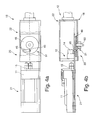
- FIGS. 4a and b is a schematic plan view and side view in partial section of a further alternative embodiment of the device 18 is shown.
- the drive device 31 comprises a circular disk 48, by means of which a displacement movement can be controlled.
- the circular disc 48 has a guide pin 45, which engages in a link 46.
- Such a drive mechanism 31 can, for example, be controlled by an external key which acts on an axis 50 of the circular disk 48, in particular on a square connection. Otherwise, the comments on the previous figures apply
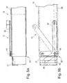
- FIG. 5a is an alternative embodiment of a lever mechanism 41 to FIG. 2a shown.
- FIG. 5a shows a sectional arrangement along the line a - b in FIG. 5b
- the lever arm 42 is formed as an L-shaped lever. This may, for example, be provided laterally outside the receiving device 22.
- the short leg in turn has a guide pin 45 which engages in a link 46 which is in communication with the receiving device 21.
- the receiving device 22 may be formed as a U-shaped housing, in which the likewise U-shaped receiving device 21 is guided, so that the Sliding motion is aligned.
- the receiving device 22 or 21 of halves 25 according to FIG. 1 consist.
- FIG. 5c a further alternative embodiment of a drive device 31 is shown schematically in a side view.
- the drive device 31 is designed as a rack drive 47, which comprises a rack 51 which is attached to the receiving device 21 for the flash lamp 11.
- the receiving device 21 may be provided detachably to the rack 51.
- this rack drive 47 comprises a gear 52 which engages the rack 51 and whose axis is mounted in the receiving device 22.
- the gear 52 for example via a rotary knob or by means of an external key, the sliding movement of the receiving device 21 can be generated.
- a manual rotation of the gear 52 may also be provided a motor drive.
- the rack 51 may alternatively be arranged on the underside of the receiving device 21.
- a rack 51 and a gear 52 of the rack drive 47 can be arranged on both longitudinal sides of the receiving device 21.
- FIG. 6 is a schematic sectional view of another alternative embodiment of the device 18 is shown.
- This device 18 is in a housing 56 of a handpiece 55.
- a spindle drive 53 is provided as a drive device 31.
- This spindle drive 53 may have at a connection point 54 for an external tool for rotating the spindle drive 53. Alternatively, the tool may also be fixedly attached thereto.
- Such a spindle drive 53 has the advantage that particularly small torques are provided for generating a sliding movement.
- the accessibility to replace the flash lamp 11 is provided via a cover 57 on the housing 56 of the handset 55, through which after opening the housing interior is accessible.
- an outlet opening 58 is provided through which the pulse light can be used to treat the affected skin.
- the figures described above may alternatively be controlled by a motor drive for manual initiation of the sliding movement, so that instead of a considerably force-reduced sliding movement by the respective lever mechanisms also a force-free sliding movement for the user to exchange a flashlamp 11 may be provided.
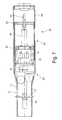
- FIG. 7 is a schematic plan view of another alternative device 18 is shown.
- This device 18 has a receiving device 22 for the flash lamp holder 12, in which a spindle 61 is driven by a motor 60 to generate the sliding movement.
- the spindle 61 is connected to a spindle nut 62, whereby the receiving device 21 is displaceable relative to the receiving device 22.
- the receiving device 21, 22 is in this case preferably designed as a top loader.
- FIG. 8 is a schematic side view of an alternative embodiment to FIG. 7 shown.
- This embodiment differs in that the driving device 21 for the flash lamp 11 is formed as a side loader. Otherwise, the embodiment corresponds to FIG FIG. 7 ,
- the motor 60 of the drive device 31 can be equipped with both an internally arranged accumulator, in particular a battery, as well as with an external unit for power supply. These two alternatives are basically possible with all motor-driven drive units 31.
- the drive device 31 may alternatively be driven pneumatically, hydraulically or electromagnetically to the electric motor.
- FIG. 9a is a schematic sectional view of another alternative embodiment of the device 18 is shown.
- FIG. 9b shows a sectional view along the line a - b according to FIG. 9a
- the receiving device 21 of the flash lamp 11 is shown as a side loader.
- the receiving device 22 comprises the drive device 31.
- a sliding movement between the receiving device 21 and the receiving device 22 is provided via a linkage 65 and a motor 60. All components required for this purpose can be provided to the housing 56 of the receiving device 22.
- Such a closed arrangement allows integration of the device 18 for changing a flashlamp 11 into a handset 55.
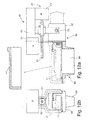
- FIGS. 10a and b schematic side views of another alternative embodiment of the device 18 are shown.
- FIG. 10c shows a schematic sectional view of the device 18 according to FIG. 10a ,
- the flashlamp 11 is housed in the housing 56 of the handset 55.
- the device 18 is accommodated in the supply part for the pulse light device or in an external device.
- the device 18 separates the housing 56 of the handset 55 into two halves.
- One half represents the receiving device 22.
- the other half represents the receiving device 21, wherein this receiving device 21 is formed, for example, in two parts and has an inner slide 67, which is fastened to the receiving device 21 via a knurled screw 68.
- Such a handset 55 is inserted by means of pins 69 in a fork 70 in the central region of the handset 55.
- a drive device 31 the flash lamp 11 is pulled out of the flash lamp holder 12.
- the flash lamp 11 is removed from the receiving device 21 without force.
- the insertion and insertion of the flash lamp 11 in the flash lamp holder 12 is done in reverse order.
- a lock of the two housing halves opens.
- FIG. 11a is a schematic side view of another alternative embodiment of the device 18 is shown.
- the FIGS. 11b and c show further schematic sectional views of the embodiment according to FIG. 11a ,
- the device 18 is in turn integrated into a handset 55 or part of a handset 55.
- a locking device engages 72, which is attached to the receiving device 21 and the housing 56 of the receiving device 21, on a pin 73 which is provided on the receiving device 22.
- the drive device 31 by means of a motor 60 cause a sliding movement, so that the receiving device 21 is withdrawn from the receiving device 22.
- a coupling 75 is provided, so that the device 18 is on the one hand connected to the motor 60 and on the other hand fixed via the pin 73 in a holder 76, which are provided as the motor 60 stationary.
- FIGS. 12a and 12b another alternative embodiment of a device 18 is provided, which acts on the handset 55 to allow replacement of the flash lamp 11.
- This device 18 is designed as a separate tool and can be positioned to the handset 55.
- a cover 57 of the housing 56 is first opened or removed by the handset 55.
- a pickup device 21 is positioned on the flash lamp 11.
- This receiving device 21 may, for example, comprise two grippers, which act positively and non-positively after the positioning of the flash lamp 11 under the influence of force.
- a spindle 61 is driven via a drive device 31 with a motor 60, as a result of which the receiving device 21 is removed relative to the receiving device 22.
- the sliding movement is initiated via the spindle 61 and the spindle nut 62, which is provided on the receiving device 21.
- the device 18 By supporting the device 18 on a holder or on a pin 73 which is provided on the housing 56 of the handset 55, there is a defined positioning of the device 18 to the handset 55 of the pulse light device.
- the mounting of the flash lamp 11 takes place in the reverse order.
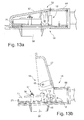
- FIGS. 13a and b is a schematic sectional view of an alternative embodiment of the handset 55 shown.
- This in turn comprises a housing 56 with an openable lid 57.
- Bei This embodiment is carried out simultaneously with an opening movement of the lid 57, a loosening and connecting the flash lamp 11 from or to the flash lamp holder 12.
- a guide pin 45 is provided on the cover 57, which is part of the receiving device 22, which at a gate 46 of the receiving device 21st attacks.
- the pivoting movement creates a sliding movement.
- the flash lamp 11 can be removed upwards.
- This embodiment has the advantage that simultaneously with the opening of the lid 57 or closing of the lid 57, a mounting or dismounting of the flash lamp 11 takes place.
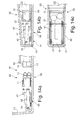
- FIGS. 14a to c are schematic sectional views of another alternative embodiment of the device 18 is shown.
- This device 18 operates in analogy to the device 18 according to FIG. 13 ,
- a lever mechanism 41 When opening the lid 57 from the housing 56 of the handset 55 via a lever mechanism 41, a loosening or connecting the flash lamp 11 to the flash lamp holder 12.
- the length of the lever arm 42 and the distance of a hinge point 79 to the pivot axis 43 of the lid 57 on the housing 56 is in turn set the power reduction for releasing and connecting the flash lamp 11 to the flash lamp holder 12.
- FIG. 15 is another schematic sectional view of the embodiment according to FIG. 13 shown.
- one or more solenoids 85 are provided to prevent opening of the lid 57 from the housing 56 until all electrical connections in the handset 55 are de-energized and the cooling water system is depressurized.
- switches 86, 87 may be provided which are actuated upon opening of the lid 57. These can be used to de-energize the electrical connections in the handset 55 and to depressurize the cooling water system.
- the opening of the lid 57 can be detected and detected. The unintentional opening of the lid 57 can be detected by other sensors that work with any physical principles, and in corresponding Protective measures are implemented.
- a sensor 88 is designed as a quiescent current loop.
- the handheld device 55 is checked by the pulsed light device as to whether the flashlamp 11 in the flashlight receptacle 12 is completely inserted.
- a check can be carried out by means of a switch 89, by means of a closed-circuit current loop, by means of a force sensor or by means of a switch based on any other physical principle.
Landscapes
- Physics & Mathematics (AREA)
- Health & Medical Sciences (AREA)
- Surgery (AREA)
- Optics & Photonics (AREA)
- Life Sciences & Earth Sciences (AREA)
- Engineering & Computer Science (AREA)
- Molecular Biology (AREA)
- Nuclear Medicine, Radiotherapy & Molecular Imaging (AREA)
- Electromagnetism (AREA)
- Biomedical Technology (AREA)
- Heart & Thoracic Surgery (AREA)
- Medical Informatics (AREA)
- Otolaryngology (AREA)
- Animal Behavior & Ethology (AREA)
- General Health & Medical Sciences (AREA)
- Public Health (AREA)
- Veterinary Medicine (AREA)
- Stroboscope Apparatuses (AREA)
- Surgical Instruments (AREA)
Applications Claiming Priority (1)
| Application Number | Priority Date | Filing Date | Title |
|---|---|---|---|
| DE102008025069 | 2008-05-26 |
Publications (1)
| Publication Number | Publication Date |
|---|---|
| EP2127609A1 true EP2127609A1 (fr) | 2009-12-02 |
Family
ID=41047449
Family Applications (1)
| Application Number | Title | Priority Date | Filing Date |
|---|---|---|---|
| EP09006951A Withdrawn EP2127609A1 (fr) | 2008-05-26 | 2009-05-25 | Dispositif de changement d'une lampe éclair sur une réception de lampe éclair |
Country Status (2)
| Country | Link |
|---|---|
| EP (1) | EP2127609A1 (fr) |
| DE (1) | DE202009017914U1 (fr) |
Citations (10)
| Publication number | Priority date | Publication date | Assignee | Title |
|---|---|---|---|---|
| US2357105A (en) * | 1943-06-19 | 1944-08-29 | G C A Mfg Co | Pull type lamp replacer |
| GB571459A (en) * | 1944-04-17 | 1945-08-24 | Herbert Henry Harvey | Improvements in or relating to grabs and like devices |
| GB2198383A (en) * | 1986-11-22 | 1988-06-15 | Anthony Francis Flanagan | Gripping device |
| DE4001135A1 (de) * | 1990-01-17 | 1990-05-17 | Halloform Gmbh & Co Kg | Zange zur handhabung von halogenlampen |
| US5033960A (en) * | 1990-11-05 | 1991-07-23 | Midwest Dental Products Corporation | Dental handpiece connector assembly with replaceable air-cooled lamp and insertion/extraction tool therefor |
| DE29919278U1 (de) * | 1999-11-03 | 2000-02-03 | Top Light, 33602 Bielefeld | Leuchtmittelwechseleinrichtung |
| US6167602B1 (en) * | 1997-03-13 | 2001-01-02 | Taiwan Semiconductor Manufacturing Co., Ltd. | Lamp removal tool |
| DE20112815U1 (de) * | 2001-08-01 | 2001-11-08 | Domnick, Manfred, 12351 Berlin | Vorrichtung zum Handhaben von Stiftsockellampen |
| US20050035614A1 (en) * | 2003-08-11 | 2005-02-17 | Ralph Wessel | Light bulb puller |
| WO2007007167A1 (fr) | 2005-07-13 | 2007-01-18 | Perkinelmer Optoelectronics Gmbh & Co. Kg | Cartouche de lampe-eclair pouvant etre branchee amovible a une douille |
-
2009
- 2009-05-25 EP EP09006951A patent/EP2127609A1/fr not_active Withdrawn
- 2009-05-25 DE DE202009017914U patent/DE202009017914U1/de not_active Expired - Lifetime
Patent Citations (10)
| Publication number | Priority date | Publication date | Assignee | Title |
|---|---|---|---|---|
| US2357105A (en) * | 1943-06-19 | 1944-08-29 | G C A Mfg Co | Pull type lamp replacer |
| GB571459A (en) * | 1944-04-17 | 1945-08-24 | Herbert Henry Harvey | Improvements in or relating to grabs and like devices |
| GB2198383A (en) * | 1986-11-22 | 1988-06-15 | Anthony Francis Flanagan | Gripping device |
| DE4001135A1 (de) * | 1990-01-17 | 1990-05-17 | Halloform Gmbh & Co Kg | Zange zur handhabung von halogenlampen |
| US5033960A (en) * | 1990-11-05 | 1991-07-23 | Midwest Dental Products Corporation | Dental handpiece connector assembly with replaceable air-cooled lamp and insertion/extraction tool therefor |
| US6167602B1 (en) * | 1997-03-13 | 2001-01-02 | Taiwan Semiconductor Manufacturing Co., Ltd. | Lamp removal tool |
| DE29919278U1 (de) * | 1999-11-03 | 2000-02-03 | Top Light, 33602 Bielefeld | Leuchtmittelwechseleinrichtung |
| DE20112815U1 (de) * | 2001-08-01 | 2001-11-08 | Domnick, Manfred, 12351 Berlin | Vorrichtung zum Handhaben von Stiftsockellampen |
| US20050035614A1 (en) * | 2003-08-11 | 2005-02-17 | Ralph Wessel | Light bulb puller |
| WO2007007167A1 (fr) | 2005-07-13 | 2007-01-18 | Perkinelmer Optoelectronics Gmbh & Co. Kg | Cartouche de lampe-eclair pouvant etre branchee amovible a une douille |
Also Published As
| Publication number | Publication date |
|---|---|
| DE202009017914U1 (de) | 2010-08-12 |
Similar Documents
| Publication | Publication Date | Title |
|---|---|---|
| EP2830825B1 (fr) | Dispositif de fixation magnétique | |
| DE3407030C1 (de) | Vorrichtung zur Zubereitung von Heissgetraenken | |
| EP0679476B1 (fr) | Pince de puissance | |
| EP2063443B1 (fr) | Dispositif d'arrêt d'urgence | |
| EP0171453A1 (fr) | Dispositif de verrouillage de sécurité de dispositifs protecteurs pour prévenir l'accès dans des zones dangereuses | |
| EP3049008B1 (fr) | Instrument chirurgical à haute fréquence | |
| DE202013011818U1 (de) | Werkzeuggerät | |
| EP0681864B1 (fr) | Mélangeur biaxial | |
| DE2338617B2 (de) | Elektrische Widerstandsschweißvorrichtung mit programmgesteuerter drehbarer Schweißeinheit | |
| DE3816547C2 (de) | Lichtquellenanordnung für medizinische Apparate | |
| DE112016002265B4 (de) | Anbringungsvorrichtung und Anbringungsverfahren für ein elektrisches Gerät | |
| EP1841559A1 (fr) | Changeur de capsules de soudage par point | |
| DE102016107648B3 (de) | Fräsmaschine mit einer Spannvorrichtung für einen ein Werkstück lagefest aufnehmenden Spannrahmen | |
| DE3839932A1 (de) | Stromversorgungseinheit | |
| EP2127609A1 (fr) | Dispositif de changement d'une lampe éclair sur une réception de lampe éclair | |
| DE102014116648B4 (de) | Mikroskop mit zwei Zugriffsöffnungen zur Fluoreszenzeinrichtung | |
| EP1657485B1 (fr) | Appareil électrique à usage personnel | |
| DE102014210330A1 (de) | Greifbackensicherung | |
| WO2008084078A1 (fr) | Dispositif de dépôt thermique | |
| DE102015109429B3 (de) | Vorkonfektioniereinrichtung | |
| DE3208621A1 (de) | Werkzeugspann - und wechselvorrichtung | |
| DE3021065C2 (de) | Einrichtung zum automatischen Einstellen der je nach Größe der verwendeten Schleifscheibe höchstzulässigen Drehzahl des Schleifscheibenantriebsmotors von Schleifmaschinen | |
| DE29508794U1 (de) | Wechseleinrichtung für Werkzeuge, Meßgeräte oder andere Wirksysteme an Manipulatorfahrzeugen | |
| WO2009143792A1 (fr) | Appareil électrique encapsulé, résistant à la pression | |
| DE2020076B2 (de) | Gerät zum Festhalten und maschinellen Betätigen eines Werkzeugs |
Legal Events
| Date | Code | Title | Description |
|---|---|---|---|
| PUAI | Public reference made under article 153(3) epc to a published international application that has entered the european phase |
Free format text: ORIGINAL CODE: 0009012 |
|
| AK | Designated contracting states |
Kind code of ref document: A1 Designated state(s): AT BE BG CH CY CZ DE DK EE ES FI FR GB GR HR HU IE IS IT LI LT LU LV MC MK MT NL NO PL PT RO SE SI SK TR |
|
| STAA | Information on the status of an ep patent application or granted ep patent |
Free format text: STATUS: THE APPLICATION HAS BEEN WITHDRAWN |
|
| 18W | Application withdrawn |
Effective date: 20100520 |