EP2127750A2 - Fermeture pour un récipient destiné à la réception d'échantillons liquides et récipient en étant équipé - Google Patents
Fermeture pour un récipient destiné à la réception d'échantillons liquides et récipient en étant équipé Download PDFInfo
- Publication number
- EP2127750A2 EP2127750A2 EP09011241A EP09011241A EP2127750A2 EP 2127750 A2 EP2127750 A2 EP 2127750A2 EP 09011241 A EP09011241 A EP 09011241A EP 09011241 A EP09011241 A EP 09011241A EP 2127750 A2 EP2127750 A2 EP 2127750A2
- Authority
- EP
- European Patent Office
- Prior art keywords
- closure
- container
- closed position
- examination device
- elements
- Prior art date
- Legal status (The legal status is an assumption and is not a legal conclusion. Google has not performed a legal analysis and makes no representation as to the accuracy of the status listed.)
- Withdrawn
Links
Images





Classifications
-
- B—PERFORMING OPERATIONS; TRANSPORTING
- B01—PHYSICAL OR CHEMICAL PROCESSES OR APPARATUS IN GENERAL
- B01L—CHEMICAL OR PHYSICAL LABORATORY APPARATUS FOR GENERAL USE
- B01L3/00—Containers or dishes for laboratory use, e.g. laboratory glassware; Droppers
- B01L3/50—Containers for the purpose of retaining a material to be analysed, e.g. test tubes
- B01L3/508—Rigid containers without fluid transport within
- B01L3/5082—Test tubes per se
- B01L3/50825—Closing or opening means, corks, bungs
-
- B—PERFORMING OPERATIONS; TRANSPORTING
- B01—PHYSICAL OR CHEMICAL PROCESSES OR APPARATUS IN GENERAL
- B01L—CHEMICAL OR PHYSICAL LABORATORY APPARATUS FOR GENERAL USE
- B01L2200/00—Solutions for specific problems relating to chemical or physical laboratory apparatus
- B01L2200/14—Process control and prevention of errors
- B01L2200/141—Preventing contamination, tampering
-
- B—PERFORMING OPERATIONS; TRANSPORTING
- B01—PHYSICAL OR CHEMICAL PROCESSES OR APPARATUS IN GENERAL
- B01L—CHEMICAL OR PHYSICAL LABORATORY APPARATUS FOR GENERAL USE
- B01L2300/00—Additional constructional details
- B01L2300/04—Closures and closing means
- B01L2300/046—Function or devices integrated in the closure
- B01L2300/049—Valves integrated in closure
-
- G—PHYSICS
- G01—MEASURING; TESTING
- G01N—INVESTIGATING OR ANALYSING MATERIALS BY DETERMINING THEIR CHEMICAL OR PHYSICAL PROPERTIES
- G01N35/00—Automatic analysis not limited to methods or materials provided for in any single one of groups G01N1/00 - G01N33/00; Handling materials therefor
- G01N2035/00178—Special arrangements of analysers
- G01N2035/00277—Special precautions to avoid contamination (e.g. enclosures, glove- boxes, sealed sample carriers, disposal of contaminated material)
- G01N2035/00287—Special precautions to avoid contamination (e.g. enclosures, glove- boxes, sealed sample carriers, disposal of contaminated material) movable lid/cover for sample or reaction tubes
Definitions
- the invention relates to a closure for a container of the type specified in the preamble of claim 1. Furthermore, the device relates to a container with a closure according to the invention.
- Such containers are used in particular in the analysis area, where various samples, in particular biological sample material, such as blood, urine, cerebrospinal fluid, saliva but also tissue samples etc., are examined. These are preferably liquid or flowable resp. lysed and / or in-solution samples (materials).
- the sample containers are usually kept closed in order to protect on the one hand the sample contained therein, but on the other hand also to protect persons who must handle the samples from possible infections. Now, using conventional lids, they must be removed before the examination of the sample. There is a risk that something of the sample may be spilled or splashed, which significantly increases the risk of infection but also the risk of contamination. It can also happen that after the examination, the lids of the sample tubes are reversed, which is also to avoid since As a result, the samples are mixed and the examination results can be falsified.
- the document DE 76 10 107 describes a plug for a sample tube with an upper and a lower part, which are each provided with a bore. By rotating the upper and lower parts against each other, the sample tube can be opened or closed.
- the disadvantage here, however, is that the opening or closing must be done manually. This means an increased workload for the operator.
- the plug lid has on its inside a circumferential bead and on its outer side an annular projection with a parallel to the cover undercut.
- a shutter disc is used.
- Both the lid and the closure disk have a plurality of openings, wherein the openings in the lid can be closed or opened by rotation of the closure disk.
- this plug is not rotatable by the examination device itself and must therefore be opened manually.
- the structure is complicated, which makes the plug expensive.
- the object of the invention is therefore to provide a closure for a sample container which can be actuated by the examination device and in which contamination and contamination of the samples or the examination device are avoided. Furthermore, it is an object of the invention to provide a container whose lid can be actuated by the examination device. This task is done by the characterizing features of claims 1 and 18, which have the following special significance.
- the closure has means which can be brought into operative connection with the operating parts located on the examination device. Due to the interaction of the means and the operating parts of the examination device, the closure can be reversibly converted into its open position. This results, for example, in the advantage that an operator who is commissioned to examine samples by means of an examination device only has to supply the container provided with the closure to the examination device. The opening of the container is then done automatically by the examination device. This reduces the workload for the operator and further minimizes the risk of contamination and contamination. Because the closure can be reversibly transferred in its open position, it is also possible to bring it back to its closed position. This further serves to protect against contamination, but also prevents contamination of the sample, if, for example, further investigations should be carried out at a later date or in another device. If the investigations are completed, the container may optionally be added directly to the waste with the remainder of the sample and the closure, without any further risk of contamination.
- the container according to the invention is provided with the closure just described. This results in the advantages described for the handling of the container.
- the closure is transferred by the examination device directly or indirectly back to its closed position.
- the operator then only needs to remove the container again after the examination, without having to worry about the transfer to the closed position.
- the closure in this context means "directly" that the examination device actively transferred by the same or other operating parts, the closure back into the closed position.
- an indirect transfer of the closure in the closed position this is done by omitting caused by the examination device external circumstances.
- the container likewise encompassed by the invention serves to receive liquid, in particular biological samples, which is intended for introduction into an examination device.
- Container and closure in this case form, for example, a structural unit. These parts can be made in one piece or in several parts.
- the closure may be secured to the container by a releasable connection, such as a screw or clip connection. However, a non-detachable connection is also possible.
- the Fig. 1 to 3 show a first embodiment of a closure 10 according to the invention. It can be seen the Loselement 40.1, which has an opening 45.1. This Loselement 40.1 is rotatably mounted with respect to the underlying fixed element 11.1.
- the fixed element 11.1 is fixedly attached to the container 20, not shown here.
- the fixed element 11.1 also has an opening 41.1, in Fig. 1 and 2 , shown in dashed lines, on.
- By rotation of the Losides 40.1 the two openings 41.1 and 45.1 are brought into a mutually aligned position, as from Fig. 3 to recognize. It is also possible to provide only a partially aligned position of the openings 41.1 and 45.1. Also, both openings need not be the same size and shape.
- Fig. 4 now shows a second embodiment of the closure 10 according to the invention according to Fig. 1 ,
- the openings 41.1 and 45.1 are circular sector here.
- the two openings 41.1 and 45.1 can be brought into an at least partially aligned position here, too.
- Fig. 5 now shows a container 20 according to the invention with closure 10 according to the invention. Also, this closure 10 has a fixed element 11.1 and a Loselement 40.1. Both elements 11.1, 40.1 have openings 41.1, 45.1.
- the closure 10 according to the invention can be transferred from the present closed position into an open position. The movement of the Losements 40.1 is thus rotational.
- the Loselement 40.1 has two stops 80.1, 80.2, while the fixed element 11.1 has a counter-stop 81.
- the first stop 80.1 and the counter-stop 81 are in operative connection with each other. If the Loselement 40.1 is now moved along its direction of movement 43.1, then the counter-stop 81 with the first stop 80.1 disengaged and instead with the second stop 80.2 in operative connection.
- This has the advantage that the closure not inadvertently, for example, by shaking movements during transport of the container 20 and in the examination device 30 is transferred to its open or closed position.
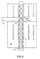
- Fig. 6 shows a part of the examination device 30 or one of the actual examination device upstream opening device. It can be clearly seen how several, with a closure 10 according to the invention Fig. 1 to 3 loaded container 20 are inserted into the examination device 30.
- an actuator 31 is provided, which moves the respective Loside 40.1 of the fasteners 10 in its direction of rotation 43.1, so as to bring the opening 45.1 of the Loselements 40.1 with the opening 41.1 of the fixed element 11.1 in an aligned position.
- a similar actuator 31 can again be provided in the examination device 30 or this again to transfer the closures 10 back into their closed position.
- the in Fig. 6 serve shown actuator 31, if you either still further rotates the Losement 40.1, or they pass in the actuator 43.1 opposite direction on the actuator 31 until the openings 45.1 and 41.1 are brought out of their aligned position again.
- Fig. 7 is again a container 20 with a closure 10 according to the invention in the already in Fig. 6 shown examination device 30 shown.
- the container 20 has again been introduced into an additional receptacle.
- the surface of the outer side 44 of the Losenses 40.1 on the closure 10 is particularly designed so as to be moved by frictional engagement of the actuator 31 in its direction of movement 43.1.
- This special surface texture of the outer side 44 functions here as a means for actuating the closure 10 in the examination device 30.
- FIG Fig. 8 A further embodiment of the closure 10 according to the invention is shown in FIG Fig. 8 shown.
- the closure 10 again has the fixed element 11.1 and the Loselement 40.1 with the openings 41.1 and 45.1. Additionally points the closure 10 also has two recesses 72, which serve as connecting means, as shown in FIGS Fig. 9a to 9c can be seen in more detail.
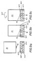
- the Fig. 9a to 9c show a removal unit 71, which has mating connection means, in this case via projections 73, has.
- the removal unit 71 contains the channel (not shown in more detail here) for introducing a pipette or another component which can take sample material out of the opened container 20.
- the closure 10 in turn consists of a fixed element 11.1 and a Loselement 40.1. Both elements 11.1, 40.1 have openings 41.1, 45.1, which in the Fig. 9a and 9b are in a non-aligned position, so that the shutter 10 is in its closed position.
- the Loselement 40.1 By rotation of the removal unit 71 in the direction of movement 43.1, the Loselement 40.1 is moved so that the openings 41.1 and 45.1 come into an aligned position, as from Fig. 9c seen.
- the transmission of the rotational movement of the removal unit 71 on the Loselement 40.1 takes place via the interaction of designed as projections 73 counter-connecting means designed as recesses 72 connecting means.
- the transfer of the closure 10 according to the invention back into the closed position, after sample material has been removed for examination, can now again take place via a rotation of the removal unit 71 counter to the direction of movement 43.1.
- FIG. 10a, 10b and 11a, 11b Another preferred embodiment of a closure 10 according to the invention show the Fig. 10a, 10b and 11a, 11b.
- the fixed element 11.3 in this case has the opening 41.3. This is closed in the illustrated closed position by two loose elements 40.3 'and 40.3 ", the opening 41.3 being the only opening in the upper side of the container 20.
- the movement of the loose elements 40.3 'and 40.3 can take place mechanically, but it is also possible for one or both of the loose elements to be wholly or partially made of magnetic or magnetizable material, and the magnetic field can be generated by applying a magnetic field Fig. 11a and 11b shown to bring about disclosed. If the container 20 provided with the closure 10 is then brought out of the magnetic field, the loose elements 40.3 'and 40.3 "automatically move back into their closed position, so that they are brought back indirectly by the examination device 30.
- FIG. 12a and 12b A similar embodiment show the Fig. 12a and 12b ,
- the opening 41.3 is closed by the Loselement 40.3 'to the in Fig. 12a shown closed position bring about.
- the Loselement 40.3 ' consists at least partially of a magnetic or magnetizable material. It is also conceivable that the Loselement 40.3 'is provided with a magnetic or magnetizable coating.
- the closure 10 still has the electromagnet 50. If the electromagnet 50 is acted upon by the voltage source 51 with a voltage, the in Fig. 12b shown open position brought about and the opening 41.3 is exposed, so that sample material can be removed from the container 20.
- FIG. 13a to 13e A final embodiment show the Fig. 13a to 13e ,
- the container 20 shown here has a fixed element 11.2, which in turn has an opening 41.2.
- the Loselement 40.2 Arranged above it, the Loselement 40.2, which also has an opening 45.2.
- the elements 11.2, 40.2 are acted upon by a spring 60 arranged between them.
- the fixed element 11.2 has guide edges 61, which can cooperate with counter-guide edges 62 on the Loselement 40.2. These guide edges 61 and counter-guide edges 62 serve as means which can be brought into operative connection with operating parts 70 located on the examination device 30.
- the leading edges 61 of the fixed element 11.2 have the Fig. 13a, 13b and 13e closer apparent form.
- an operating part of the examination device 30 such as a pipette tip 70 on the Loselemeat 40.2, so slide the Gegenschreibungskanten 62 of the Losiatas 40.2 at the leading edge 61 of the fixed element 11.2 down.
- the openings come 41.2 and 45.2 in the Fig. 13b apparent aligned position and the pipette tip 70 can take sample material from the container 20. If the pipette tip 70 is withdrawn from the container 20 again after the sampling has taken place, the spring element 60 will return the loose element 40.2 to its position Fig. 13a brought apparent position and the closed position of the closure 10 brought about again.
- the transfer into the shooting position thus takes place indirectly through the examination device 30.
Landscapes
- Health & Medical Sciences (AREA)
- Chemical & Material Sciences (AREA)
- Analytical Chemistry (AREA)
- General Health & Medical Sciences (AREA)
- Hematology (AREA)
- Clinical Laboratory Science (AREA)
- Chemical Kinetics & Catalysis (AREA)
- Sampling And Sample Adjustment (AREA)
- Automatic Analysis And Handling Materials Therefor (AREA)
Applications Claiming Priority (1)
| Application Number | Priority Date | Filing Date | Title |
|---|---|---|---|
| EP08008485A EP2116306A1 (fr) | 2008-05-06 | 2008-05-06 | Fermeture pour un récipient destiné à la réception d'échantillons liquides et récipient en étant équipé |
Related Parent Applications (2)
| Application Number | Title | Priority Date | Filing Date |
|---|---|---|---|
| EP08008485 Previously-Filed-Application | 2008-05-06 | ||
| EP08008485A Division EP2116306A1 (fr) | 2008-05-06 | 2008-05-06 | Fermeture pour un récipient destiné à la réception d'échantillons liquides et récipient en étant équipé |
Publications (2)
| Publication Number | Publication Date |
|---|---|
| EP2127750A2 true EP2127750A2 (fr) | 2009-12-02 |
| EP2127750A3 EP2127750A3 (fr) | 2010-01-13 |
Family
ID=39739716
Family Applications (2)
| Application Number | Title | Priority Date | Filing Date |
|---|---|---|---|
| EP08008485A Withdrawn EP2116306A1 (fr) | 2008-05-06 | 2008-05-06 | Fermeture pour un récipient destiné à la réception d'échantillons liquides et récipient en étant équipé |
| EP09011241A Withdrawn EP2127750A3 (fr) | 2008-05-06 | 2008-05-06 | Fermeture pour un récipient destiné à la réception d'échantillons liquides et récipient en étant équipé |
Family Applications Before (1)
| Application Number | Title | Priority Date | Filing Date |
|---|---|---|---|
| EP08008485A Withdrawn EP2116306A1 (fr) | 2008-05-06 | 2008-05-06 | Fermeture pour un récipient destiné à la réception d'échantillons liquides et récipient en étant équipé |
Country Status (1)
| Country | Link |
|---|---|
| EP (2) | EP2116306A1 (fr) |
Cited By (4)
| Publication number | Priority date | Publication date | Assignee | Title |
|---|---|---|---|---|
| CN103477201A (zh) * | 2011-02-22 | 2013-12-25 | 帕尔欧洲有限公司 | 无菌采样系统 |
| US20230061233A1 (en) * | 2021-01-27 | 2023-03-02 | Sarvjit Gill | Multi-component sample container cap |
| WO2023192679A1 (fr) * | 2022-04-01 | 2023-10-05 | Gill, Llc | Capuchon d'échantillon à verrouillage |
| US12595098B2 (en) | 2022-04-01 | 2026-04-07 | Sarvjit Gill | Fluid sample container cap |
Families Citing this family (2)
| Publication number | Priority date | Publication date | Assignee | Title |
|---|---|---|---|---|
| ITMS20110006A1 (it) * | 2011-09-16 | 2013-03-17 | Dino Cagetti | Supporto "dinamico" copri tappo di protezione, capace di mantenere la sterilità del cratere del tappo di gomma della provetta fino all'istante prima dell'incontro del tappo stesso con l'ago perforatore sterile. le provette sono quelle sottovuoto usat |
| JP7538612B2 (ja) * | 2020-03-30 | 2024-08-22 | シスメックス株式会社 | 試料調製装置 |
Citations (4)
| Publication number | Priority date | Publication date | Assignee | Title |
|---|---|---|---|---|
| US2672257A (en) | 1950-04-18 | 1954-03-16 | Irving H Simmonds | Magnetic container cap |
| DE7610107U1 (de) | 1976-04-01 | 1976-10-21 | Groth, Kaethe, 2000 Hamburg | Stopfen fuer probenroehren mit verschliessbarer entnahme-einrichtung |
| DE3201691A1 (de) | 1982-01-21 | 1983-09-08 | K.J. Steingass GmbH, 5275 Bergneustadt | Stopfen fuer behaelter und proberoehrchen |
| CH658438A5 (en) | 1981-10-22 | 1986-11-14 | Saseb Ag | Closure for containers |
Family Cites Families (5)
| Publication number | Priority date | Publication date | Assignee | Title |
|---|---|---|---|---|
| DE955542C (de) * | 1955-08-16 | 1957-01-03 | Paul Funke & Co G M B H | Verfahren und Vorrichtung zum sterilen Verschliessen und OEffnen von Reagenzgalesernund aehnlichen Glaesern |
| US4203527A (en) * | 1978-04-06 | 1980-05-20 | Lachance Ernest J Sr | Novel secure cap with depressible lock |
| US5374557A (en) * | 1993-04-29 | 1994-12-20 | Verma; Kuldeep | Fermentation vessels and closures therefor |
| GB9716763D0 (en) * | 1997-08-07 | 1997-10-15 | The Technology Partnership Plc | Chemical vessel cap |
| DE102004043883B4 (de) | 2004-09-10 | 2007-04-19 | Bartec Gmbh | Probenflaschen und Verfahren zur Probenahme |
-
2008
- 2008-05-06 EP EP08008485A patent/EP2116306A1/fr not_active Withdrawn
- 2008-05-06 EP EP09011241A patent/EP2127750A3/fr not_active Withdrawn
Patent Citations (4)
| Publication number | Priority date | Publication date | Assignee | Title |
|---|---|---|---|---|
| US2672257A (en) | 1950-04-18 | 1954-03-16 | Irving H Simmonds | Magnetic container cap |
| DE7610107U1 (de) | 1976-04-01 | 1976-10-21 | Groth, Kaethe, 2000 Hamburg | Stopfen fuer probenroehren mit verschliessbarer entnahme-einrichtung |
| CH658438A5 (en) | 1981-10-22 | 1986-11-14 | Saseb Ag | Closure for containers |
| DE3201691A1 (de) | 1982-01-21 | 1983-09-08 | K.J. Steingass GmbH, 5275 Bergneustadt | Stopfen fuer behaelter und proberoehrchen |
Cited By (6)
| Publication number | Priority date | Publication date | Assignee | Title |
|---|---|---|---|---|
| CN103477201A (zh) * | 2011-02-22 | 2013-12-25 | 帕尔欧洲有限公司 | 无菌采样系统 |
| CN103477201B (zh) * | 2011-02-22 | 2015-06-17 | 帕尔欧洲有限公司 | 无菌采样系统 |
| US20230061233A1 (en) * | 2021-01-27 | 2023-03-02 | Sarvjit Gill | Multi-component sample container cap |
| US12397975B2 (en) * | 2021-01-27 | 2025-08-26 | Gill, Llc | Multi-component sample container cap |
| WO2023192679A1 (fr) * | 2022-04-01 | 2023-10-05 | Gill, Llc | Capuchon d'échantillon à verrouillage |
| US12595098B2 (en) | 2022-04-01 | 2026-04-07 | Sarvjit Gill | Fluid sample container cap |
Also Published As
| Publication number | Publication date |
|---|---|
| EP2116306A1 (fr) | 2009-11-11 |
| EP2127750A3 (fr) | 2010-01-13 |
Similar Documents
| Publication | Publication Date | Title |
|---|---|---|
| DE69307433T2 (de) | Zentralisierter Steuermechanismus mit eingebauten Sicherheiten zur Verwendung in einer abgedichteten Übertragungseinrichtung zwischen zwei geschlossenen Räumen | |
| DE69729510T2 (de) | Anordnung zur Probesammlung | |
| EP2127750A2 (fr) | Fermeture pour un récipient destiné à la réception d'échantillons liquides et récipient en étant équipé | |
| DE2061978A1 (de) | Messwertgebereinrichtung mit herausnehmbarer Messwertgebersonde | |
| DE102006019515A1 (de) | Mehrstufiger Türverschluss | |
| DE102019003317A1 (de) | Vorrichtung zur sterilen Übergabe von Gut zwischen einem Behälter und einem Isolator | |
| DE68918450T2 (de) | Transfervorrichtung für dichtungshülle. | |
| DE2333249C3 (de) | Bandkassette | |
| EP2434293B1 (fr) | Support de transport et de manipulation | |
| EP3792215B1 (fr) | Système de prélèvement | |
| EP1440448B1 (fr) | Dispositif de porte pour isolateur | |
| WO2007124926A1 (fr) | Dispositif pour prelever des liquides | |
| DE102017119140B3 (de) | Kassette zum Einlegen einer Gewebeprobe | |
| DE102011075338B3 (de) | Rohrpostbüchse | |
| DE69005054T2 (de) | Senkrecht bewegliche Verschlussvorrichtung für verschiedene Behälter. | |
| EP3232443A1 (fr) | Dispositif de securisation pour sas | |
| DE8509450U1 (de) | Vorrichtung zum Öffnen und Schließen einer Schiebetür | |
| EP4387568A1 (fr) | Injecteur pour lentille intraoculaire, et système comportant un injecteur | |
| DE102021130404A1 (de) | Dichte Vorrichtung, die Zugang zu einem Gehäuse bietet, sowie entsprechendes System zur dichten Verbindung zwischen zwei Gehäusen | |
| AT515746B1 (de) | Hülse für eine Rohrpostanlage | |
| DE202007019195U1 (de) | Schnellverschluss | |
| DE102010007952B4 (de) | Verschluss für eine Tür eines Gargeräts | |
| DE102022204581A1 (de) | Halter für einen Probenträger, insbesondere für einen Abstrich | |
| CH673157A5 (en) | Sampling valve for fluid pipeline - has external operating lever moved against return bias to open sampling valve | |
| DE955229C (de) | Deckelanordnung fuer Autoklaven |
Legal Events
| Date | Code | Title | Description |
|---|---|---|---|
| PUAI | Public reference made under article 153(3) epc to a published international application that has entered the european phase |
Free format text: ORIGINAL CODE: 0009012 |
|
| AC | Divisional application: reference to earlier application |
Ref document number: 2116306 Country of ref document: EP Kind code of ref document: P |
|
| AK | Designated contracting states |
Kind code of ref document: A2 Designated state(s): AT BE BG CH CY CZ DE DK EE ES FI FR GB GR HR HU IE IS IT LI LT LU LV MC MT NL NO PL PT RO SE SI SK TR |
|
| PUAL | Search report despatched |
Free format text: ORIGINAL CODE: 0009013 |
|
| AK | Designated contracting states |
Kind code of ref document: A3 Designated state(s): AT BE BG CH CY CZ DE DK EE ES FI FR GB GR HR HU IE IS IT LI LT LU LV MC MT NL NO PL PT RO SE SI SK TR |
|
| RIN1 | Information on inventor provided before grant (corrected) |
Inventor name: NELLES, THOMAS Inventor name: WEGENER, UTA Inventor name: MERTENS, DENNIS |
|
| 17P | Request for examination filed |
Effective date: 20100308 |
|
| RIN1 | Information on inventor provided before grant (corrected) |
Inventor name: WEGENER, UTA Inventor name: MERTENS, DENNIS Inventor name: NELLES, THOMAS |
|
| 17Q | First examination report despatched |
Effective date: 20120712 |
|
| STAA | Information on the status of an ep patent application or granted ep patent |
Free format text: STATUS: THE APPLICATION IS DEEMED TO BE WITHDRAWN |
|
| 18D | Application deemed to be withdrawn |
Effective date: 20121123 |