EP2128070A2 - Processus de pliage continu - Google Patents
Processus de pliage continu Download PDFInfo
- Publication number
- EP2128070A2 EP2128070A2 EP09006953A EP09006953A EP2128070A2 EP 2128070 A2 EP2128070 A2 EP 2128070A2 EP 09006953 A EP09006953 A EP 09006953A EP 09006953 A EP09006953 A EP 09006953A EP 2128070 A2 EP2128070 A2 EP 2128070A2
- Authority
- EP
- European Patent Office
- Prior art keywords
- folding
- corrugated cardboard
- stacking
- cardboard web
- web
- Prior art date
- Legal status (The legal status is an assumption and is not a legal conclusion. Google has not performed a legal analysis and makes no representation as to the accuracy of the status listed.)
- Granted
Links
- 238000000034 method Methods 0.000 title claims abstract description 11
- 230000008569 process Effects 0.000 title description 4
- 238000005520 cutting process Methods 0.000 claims abstract description 73
- 238000011144 upstream manufacturing Methods 0.000 claims abstract description 11
- 238000004049 embossing Methods 0.000 claims description 56
- 238000009434 installation Methods 0.000 claims description 10
- 238000004519 manufacturing process Methods 0.000 claims description 4
- 238000002788 crimping Methods 0.000 claims 1
- 238000007493 shaping process Methods 0.000 abstract 1
- 230000007246 mechanism Effects 0.000 description 13
- 238000006073 displacement reaction Methods 0.000 description 10
- 238000003780 insertion Methods 0.000 description 9
- 230000037431 insertion Effects 0.000 description 9
- 230000001360 synchronised effect Effects 0.000 description 5
- 230000007704 transition Effects 0.000 description 5
- 230000005484 gravity Effects 0.000 description 3
- 230000000284 resting effect Effects 0.000 description 3
- 238000005452 bending Methods 0.000 description 2
- 238000000151 deposition Methods 0.000 description 2
- 238000003860 storage Methods 0.000 description 2
- 206010040954 Skin wrinkling Diseases 0.000 description 1
- 229910000831 Steel Inorganic materials 0.000 description 1
- 230000009471 action Effects 0.000 description 1
- 230000001154 acute effect Effects 0.000 description 1
- 229910052782 aluminium Inorganic materials 0.000 description 1
- XAGFODPZIPBFFR-UHFFFAOYSA-N aluminium Chemical compound [Al] XAGFODPZIPBFFR-UHFFFAOYSA-N 0.000 description 1
- 230000005540 biological transmission Effects 0.000 description 1
- 238000010276 construction Methods 0.000 description 1
- 238000010924 continuous production Methods 0.000 description 1
- 230000001419 dependent effect Effects 0.000 description 1
- 230000008021 deposition Effects 0.000 description 1
- 230000000977 initiatory effect Effects 0.000 description 1
- 230000003993 interaction Effects 0.000 description 1
- 238000005304 joining Methods 0.000 description 1
- 229910052751 metal Inorganic materials 0.000 description 1
- 239000002184 metal Substances 0.000 description 1
- 230000035515 penetration Effects 0.000 description 1
- 239000010959 steel Substances 0.000 description 1
Images


Classifications
-
- B—PERFORMING OPERATIONS; TRANSPORTING
- B65—CONVEYING; PACKING; STORING; HANDLING THIN OR FILAMENTARY MATERIAL
- B65H—HANDLING THIN OR FILAMENTARY MATERIAL, e.g. SHEETS, WEBS, CABLES
- B65H45/00—Folding thin material
- B65H45/12—Folding articles or webs with application of pressure to define or form crease lines
- B65H45/20—Zig-zag folders
-
- B—PERFORMING OPERATIONS; TRANSPORTING
- B65—CONVEYING; PACKING; STORING; HANDLING THIN OR FILAMENTARY MATERIAL
- B65H—HANDLING THIN OR FILAMENTARY MATERIAL, e.g. SHEETS, WEBS, CABLES
- B65H33/00—Forming counted batches in delivery pile or stream of articles
- B65H33/02—Forming counted batches in delivery pile or stream of articles by moving a blade or like member into the pile
-
- B—PERFORMING OPERATIONS; TRANSPORTING
- B65—CONVEYING; PACKING; STORING; HANDLING THIN OR FILAMENTARY MATERIAL
- B65H—HANDLING THIN OR FILAMENTARY MATERIAL, e.g. SHEETS, WEBS, CABLES
- B65H45/00—Folding thin material
- B65H45/02—Folding limp material without application of pressure to define or form crease lines
- B65H45/06—Folding webs
- B65H45/10—Folding webs transversely
- B65H45/101—Folding webs transversely in combination with laying, i.e. forming a zig-zag pile
- B65H45/1015—Folding webs provided with predefined fold lines; Refolding prefolded webs, e.g. fanfolded continuous forms
-
- B—PERFORMING OPERATIONS; TRANSPORTING
- B65—CONVEYING; PACKING; STORING; HANDLING THIN OR FILAMENTARY MATERIAL
- B65H—HANDLING THIN OR FILAMENTARY MATERIAL, e.g. SHEETS, WEBS, CABLES
- B65H2301/00—Handling processes for sheets or webs
- B65H2301/40—Type of handling process
- B65H2301/42—Piling, depiling, handling piles
- B65H2301/421—Forming a pile
- B65H2301/4214—Forming a pile of articles on edge
- B65H2301/42144—Forming a pile of articles on edge by erecting articles from horizontal transport flushing with the supporting surface of the pile
-
- B—PERFORMING OPERATIONS; TRANSPORTING
- B65—CONVEYING; PACKING; STORING; HANDLING THIN OR FILAMENTARY MATERIAL
- B65H—HANDLING THIN OR FILAMENTARY MATERIAL, e.g. SHEETS, WEBS, CABLES
- B65H2301/00—Handling processes for sheets or webs
- B65H2301/40—Type of handling process
- B65H2301/42—Piling, depiling, handling piles
- B65H2301/421—Forming a pile
- B65H2301/4216—Forming a pile of web folded in zig-zag form
-
- B—PERFORMING OPERATIONS; TRANSPORTING
- B65—CONVEYING; PACKING; STORING; HANDLING THIN OR FILAMENTARY MATERIAL
- B65H—HANDLING THIN OR FILAMENTARY MATERIAL, e.g. SHEETS, WEBS, CABLES
- B65H2701/00—Handled material; Storage means
- B65H2701/10—Handled articles or webs
- B65H2701/17—Nature of material
- B65H2701/176—Cardboard
- B65H2701/1768—Book covers and the like
Definitions
- the invention relates to a system and a method for folding and stacking corrugated cardboard.
- corrugated board is usually done in a continuous process in which endless webs are produced. These endless webs must be kept in a suitable form after their production. For this they are folded, for example. In particular, when folding large-format corrugated webs, this can lead to undesirable kinks in the webs.
- the invention is therefore based on the object to provide a system and a method with which the folding and stacking of endless webs of corrugated board is improved.
- the essence of the invention is to arrange a folding device and a stacking device at the outlet end of a device for producing corrugated cardboard. This makes it possible to fold an endless corrugated web in a continuous manufacturing process along predetermined folds and stack up stacking.
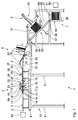
- a plant 1 for embossing, folding, stacking and cutting of endless corrugated cardboard webs 2 is arranged downstream of a device 60, which is only schematically indicated in the figures, for producing corrugated cardboard with respect to a conveying direction 3.
- a device 60 is for example from the DE 103 12 600 A1 , to which reference is hereby known.
- the means of the device 60 endless manufacturable corrugated board web 2 may have a substantially arbitrary number of layers. It has a thickness D.
- the system 1 comprises a squeezing device 4, a folding device 5, a cutting device 6 and a stacking device 7.
- the squeezing device 4 is arranged on a first platform 8, which via a first frame 9 fixed to the Ground is connected.
- the folding device 5 is connected by means of a second frame 10 fixed to the ground.
- the stacking device 7 is connected by means of a third frame 11 fixed to the ground.
- the cutting device 6 is also attached.
- the second frame 10 may be connected to the first frame 9 and / or the third frame 11.
- the frames 9, 10, 11 form a holding frame 12 for the installation 1.
- the holding frame 12 with the frames 9, 10, 11 enables a flexible, modular construction of the installation 1.
- the squeezing device 4 has an insertion section 13 with a support surface 14. In the region of the insertion section 13, two insertion rollers 15 are arranged.
- the insertion rollers 15 are cylindrical and each rotatable about an insertion roller axis 16, which is arranged perpendicular to the conveying direction 3, stored.
- the insertion rollers 15 may in particular be driven in rotation.
- the squeezing device 4 comprises at least one pair of embossing rollers 17, which are each arranged to be rotatable about an embossing roller axis 18.
- the embossing rollers 17 are preferably rotatably driven by means of a drive device, not shown in the figures.
- the drive is advantageously intermittently clocked.
- the embossing roll axes 18 are aligned parallel to one another and perpendicular to the conveying direction 3.
- the embossing roll axes 18 are vertically stacked.
- the distance of the embossing roll axes 18 to each other is adjustable.
- a passage gap 89 is formed with a free opening.
- the free opening of the feedthrough gap 89 is at least as large as the thickness D of the corrugated cardboard web 2.
- the two embossing rollers 17 are formed at least largely identical. They have a circumference U in the range of 80 cm to 140 cm.
- the embossing rollers 17 each have a stamping element 19.
- the embossing element 19 is bar-shaped, blunt. It has an extent in the radial direction, that is perpendicular to the surface of the embossing rollers 17, which is less than half of the free Opening.
- the embossing element 19 is formed continuously. However, it may also be rake-shaped, that is interrupted, be formed.
- the embossing elements 19 of the two embossing rollers 17 are arranged on the circumference of the embossing rollers 17 such that they meet at each revolution of the embossing rollers 17 about the embossing roller axes 18 on each other.
- the free opening of the lead-through gap 89 is reduced to a value which is smaller than the thickness D of the corrugated cardboard web 2.
- the corrugated cardboard web 2 can thus be squeezed by means of the embossing elements 19.
- the embossing elements 19 are preferably aligned parallel to the embossing roll axes 18 in order to emboss folds 20 in the corrugated cardboard web 2, which are oriented perpendicular to the conveying direction 3 and thus to the longitudinal direction of the corrugated cardboard web 2.
- the gap between two successive folds 20 corresponds in one embodiment just to the circumference U of the embossing rollers 17.
- the folds 20 form desired kinks in the corrugated cardboard web 2, along which this is particularly easy foldable, since they in the region of the folds 20 a smaller Bending elasticity than in the area outside of the folds 20 and therefore in the region of the folds 20 particularly easily buckles.
- embossing rollers 17 are provided whose circumference U corresponds to an integer multiple of the desired distance between two successive folds 20 in the corrugated cardboard web 2.
- the embossing rollers 17 of this type have a corresponding number of embossing elements 19 on their surface.
- the embossing elements 19 are uniformly distributed over the circumference U of the embossing rollers 17, that is, the angular distance between two adjacent embossing elements 19 is the same.
- An embossing roller 17 whose circumference U corresponds to n times the distance between two successive folds in the corrugated cardboard web 2, thus has n embossing elements 19, which are each arranged at an angular distance of 360 ° / n on its surface.
- the stamping rollers 17 are interchangeable. As a result, the distance between two successive folds 20 in the corrugated cardboard web 2, which corresponds to the circumference U of the embossing rollers 17, can be adjusted in a simple manner.
- the squeezing device 4 has an outlet section 21 in which outlet rollers 22 with outlet roller axes 23 are arranged parallel to the introduction roller axes 16.
- the outlet roller 22 arranged underneath the corrugated cardboard web 2 is part of a transport unit 24 which also has an endless conveyor belt 25.
- the folding device 5 Downstream of the squeezing device 4, that is downstream of this in the conveying direction 3, the folding device 5 is arranged.
- the folding device 5 comprises a double table 26.
- the double table 26 comprises a lower table top 27 and an upper table top 28.
- the table tops 27, 28 are arranged parallel to one another. They are so spaced apart from each other, that the corrugated cardboard web 2 can be passed between them. For this purpose, their distance to the thickness D of the corrugated cardboard web 2 is customizable.
- the upper table top 28 has an elongated opening 29, which is oriented substantially perpendicular to the conveying direction 3.
- a drive roller 30 is rotatably drivable about a drive roller axis 31 in such a way that the corrugated board web 2 sliding on the lower table plate 27 rests tangentially on the drive roller 30.
- the drive roller axle 31 is aligned perpendicular to the conveying direction 3, parallel to the axes 16, 18, 23.
- the support surface 32 connects continuously, continuously to the lower table top 27 of the double table 26.
- the support surface 32 has a kink 33, from which it is slightly sloping inclined in the conveying direction 3. It can also be bent.
- the folding device 5 further comprises a folding unit 81 arranged below the support surface 32.
- the folding unit 81 has a stand 34 arranged downstream of the double table 26.
- the stand 34 is arranged in the conveying direction 3 at a distance from the downstream end of the double table 26, which is at least as large, in particular at least one and a half times as large, in particular at least twice as large as the distance between two adjacent folds 20 in the corrugated cardboard web 2.
- the tripod 34 comprises two holding elements 35, which are arranged opposite one another transversely to the conveying direction 3 of the corrugated cardboard web 2.
- On the one of the holding elements 35 is a first drive means 36 and a second drive means 37 mounted.
- the drive device 36, 37 each includes an electric motor 38.
- the electric motor 38 of the first drive device 36 is coupled via a first belt 39 to a torque-transmitting element configured as a first folder-shaft 40 ,
- the first folder-device shaft 40 is rotatably supported about a first axis 85 in the stand 34.
- the first axis 85 is aligned perpendicular to the conveying direction 3, parallel to the axes 16, 18, 23 and 31. It is spaced by a distance A 1 to the support surface 32.
- the first folder shaft 40 is part of a frame 41 pivotally supported by the stand 34.
- the frame 41 also includes two fixed to the first folder shaft 40 in the end portions of the first folder shaft 40 and fixed to the first folder shaft 40 connected side parts 42.
- the side parts 42 are aligned parallel to the conveying direction 3.
- the side members 42 thus form arms which are perpendicular to the first folder device shaft 40.
- an engagement element 46 is rotatably mounted about a second axis 86.
- the second axis 86 is parallel to the first axis 85. It is spaced therefrom by a distance A 2 .
- the engagement member 46 is coupled via a second torque-transmitting member 44 by means of a second belt 45 to the electric motor 38 of the second drive means 37.
- the second torque transmission element 44 is according to the in the FIGS. 5 and 6 illustrated embodiment as one side in the frame 41 mounted, stepped pulley. On the opposite side of the pulley 42 of the frame, the engagement element 46 is mounted by means of a pin 87 in the side part 42. In principle it is possible to provide a second folder shaft instead of the pulley and the pin 87.
- the engagement element 46 is formed like a comb. It has a transverse beam 47 aligned along the second axis 86, with which a plurality of elongate, finger-shaped projections 49 running flat at their free ends 48 are connected corresponding to the teeth of a comb.
- the extensions 49 have measured from the second axis 86 to their free ends 48 a length L F.
- the length L F is preferably at most as large as the sum of the distance A 1 of the first axis 85 from the bearing surface 32 and the distance A 2 of the second axis 86 from the first axis 85, L F ⁇ A 1 + A 2 .
- the engagement element 46 is pivotable in the stand 34 by means of the frame 41 about the first axis 85 and in the frame 41 about the second axis 86.
- the engagement element 46 thus has two degrees of freedom, in particular two rotational degrees of freedom.
- the engagement element 46 is at least largely rigid. It is for example at least partially, in particular completely made of metal.
- the tripod 34 is adjustable in the vertical direction. As a result, the relative position of the stand 34, on which the engagement element 46 is held, relative to the support surface 32 is adjustable.
- the electric motors 38 are controllable by a control unit, not shown in the figures.
- the engagement element 46 is movable such that the free ends 48 of the extensions 49 in a fold region around the stand 34 any predetermined Trajectory parallel to the conveying direction 3 can describe.
- the free ends 48 of the projections 49 are in particular along a linear, ie rectilinear and / or curved path obliquely to the support surface 32 movable.
- the corrugated cardboard web 2 by means of the engaging element 46 of the folding unit 81 can be lifted from the support surface 32, wherein the free ends 48 of the extensions 49 form an engageable with the corrugated web 2, discontinued support edge 90, on which the corrugated cardboard web 2 rests.
- the support surface 32 is perforated, running lattice-like, wherein the grid is oriented along the conveying direction 3 in order to allow a penetration of the engagement element 46 by the support surface 32.
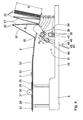
- the stacking device 7 Downstream of the folding device 5, the stacking device 7 is arranged with the cutting device 6.
- the stacking device 7 comprises at least one guide element 50 designed as a sliding surface, on which stacks 51 folded by the folding device 5 are transported along a predetermined path. Under transport, this also means the automatic sliding of the stack 51 on the guide element 50 due to gravity.
- the guide element 50 is arranged obliquely to the horizontal and thus forms an inclined plane on which the stack 51 slides.
- the guide element 50 has a first, the folding device 5 facing transition section 52, a subsequent thereto in the conveying direction 3 cutting section 53 and a removal section 54.
- the adjoining sections 52 and 53 or 53 and 54 are each connected to each other by a first joint 55 and a second joint 56 so as to be pivotable relative to each other.
- the sections 52, 53 and 54 have an increasing in the conveying direction 3 Steepness.
- the guide element 50 is thus convex. In particular, it may also be bent at least in sections, in particular in the form of a circular arc. This causes that the guide element 50 applied to the folds 20 when placing the stack 51 are closer to each other than the outer folds 20. As a result, a muted and precise deposition of the folded stack 51 is facilitated.
- the guide member 50 may advantageously comprise a belt conveyor with a conveyor belt extending over all three sections 52, 53 and 54 and a drive unit.
- the cutting portion 53 is disposed at an angle b to the horizontal.
- the inclination of the cutting portion 53 is adjustable by means of an adjusting element 57.
- the adjusting element 57 is mounted on the third frame 11. It is in particular a hydraulic or electrically actuatable adjusting element 57. In a simpler embodiment, the adjusting element 57 can also be operated manually.
- An adjustment of the inclination of the cutting portion 53 is compensated by pivoting the transition portion 52 relative to the cutting portion 53 by means of the first joint 55 such that the guide element 50 regardless of the inclination of the cutting portion 53 a steady, that is essentially forms stepless transition to the support surface 32 of the folding device 5.
- the transition section 52 has for this purpose an adjustable inclination.
- the stacking device 7 also has a plurality of stop arms 58.
- the stop arms 58 serve as an end stop and stacking surface for the stack 51 of corrugated cardboard.
- the stop arms 58 are displaceable along the guide element 50.
- the stop arms 58 are aligned perpendicular to the surface of the guide element 50. You are in a Professional known manner retractable, for example, foldable and foldable or extendable and retractable.
- the removal section 54 is at least approximately vertical, in particular vertically aligned, that is, it includes an angle c with the horizontal, which is in the range of 80 ° to 90 °.
- a value of the angle c of less than 90 ° causes the stacks 51 of corrugated cardboard to rest securely against the guide element 50 even in the region of the removal section 54 and not slip off the stop arms 58 unintentionally.
- the cutting device 6 is arranged.
- the cutting device 6 comprises a support structure 61, which is connected to the third frame 11 so as to be pivotable about a supporting structure axis 62 running perpendicular to the conveying direction 3.
- a pivotable mounting of the support structure 61 on the frame 11 it is possible to connect the support structure 61 directly to the stacking device 7, in particular to the cutting section 53 of the guide element 50 of the stacking device 7.
- a parallel alignment of the support structure 61 to the cutting section 53 is ensured in a particularly simple manner.
- a hydraulically actuated cutting unit 63 is arranged on the support structure 61.
- the cutting unit 63 is slidable on the support structure 61 parallel to the cutting portion 53 of the guide member 50 of the stacker 7. It is preferably synchronized with the sliding along the guide element 50 stop arms 58 slidably.
- the cutting unit 63 comprises a displacement mechanism 64 oriented perpendicular to the support structure 61.
- the displacement mechanism 64 is preferably a hydraulic cylinder, in particular a single-acting hydraulic cylinder with a Feder-RückstellElement.
- the hydraulic cylinder may also be designed as a double-acting hydraulic cylinder.
- the hydraulic cylinder is preferably designed as a telescopic cylinder with at least 2, in particular at least 3 cylinders built into each other.
- Alternative embodiments of the displacement mechanism 64 are also conceivable.
- On the sliding mechanism 64 a cutting element 65 is attached. By means of the displacement mechanism 64, the cutting element 65 is displaceable perpendicular to the support structure 61 and thus perpendicular to the cutting portion 53 of the guide element 50.
- the displacement mechanism 64 is dimensioned such that the cutting element 65 has a displaceability perpendicular to the support structure 61, which is greater than the maximum expected distance between two adjacent folds 20 in the corrugated cardboard web 2.
- the cutting element 65 has a total length L.
- the guide element 50 has at least one receiving groove 88 in a specific region of the cutting section 53 for receiving the cutting web. Elements 65 on.
- the receiving groove 88 has a depth T which is less than the length L of the cutting element 65.
- the receiving groove 88 In the direction parallel to the surface of the guide element 50, the receiving groove 88 has a free opening, which is significantly smaller than the thickness the corrugated web 2.
- the cutting element 65 extends in the direction of the support structure axis 62 over the entire width of the corrugated cardboard web 2. Perpendicular thereto and perpendicular to its longitudinal direction, the cutting element 65 a Strength S, which is at most 5 cm, in particular less than 3 cm, in particular less than 1 cm.
- the cutting element 65 is designed in particular as an insert made of aluminum with a cutting blade made of steel.
- the cutting plate preferably has elongated holes.
- the cutting element 65 has a sufficient transverse rigidity, so that it can at least temporarily take over the support function of the stop arms 58.
- the cutting element 65, in particular its blade, is replaceable.
- the properties of the cutting element 65 in particular its thickness S to the properties of each produced corrugated cardboard web 2, for example, the thickness D, the number of layers and their surface properties are adaptable. Due to its small thickness S, the cutting element 65 is particularly easy between two stacked in the stack 51 portions of the corrugated cardboard sheet 2 in the stack 51 inserted. By the pivotability of the support structure 61 about the support structure axis 62 can be ensured that the cutting element 65 is displaceable by means of the sliding mechanism 64 parallel to the stacked 51 sections of the corrugated cardboard web 2.
- a displaceable by means of the sliding mechanism 64 stop member is provided instead of the cutting element 65.
- the stop element preferably has a groove.
- a circular blade is provided for separating the stacks 51 from the upstream corrugated board web 2.
- the circular blade is connected via a guide with the third frame 11.
- a perpendicular to the conveying direction 3 extending cross member is preferably provided.
- separating the stack 51 from the upstream corrugated cardboard web 2 acts the circular blade with the stop element together. It preferably engages in the groove of the stop element.
- the separated by means of the cutting device 6 of the corrugated web 2 stack 51 can be removed from the removal section 54 by means of a removal device 66 shown only schematically in the figures for further transport and storage.
- the corrugated cardboard webs 2 for example, from the DE 103 12 600 A1 produced by known methods.
- one or more cover sheets with one or more corrugated webs are connected to each other in a method known in the art, with respect to the details on behalf of the DE 43 05 158 A1 is referenced.
- the endless corrugated board web 2 coming from the device 60 is embossed in the squeezing device 4.
- the corrugated board web 2 is passed between the two embossing rollers 17.
- the two embossing elements 19 meet, whereby the free opening of the feed-through gap 89 between the embossing rollers 17 to a value A S2 , which is less than the thickness D of the corrugated cardboard web 2, is reduced, so that in the corrugated cardboard web 2, which is currently passed between the embossing elements 19, the fold 20 is impressed.
- embossing rollers 17 and / or the arrangement of the embossing elements 19 on the same are precisely coordinated with each other for this purpose. This applies accordingly, if the embossing rollers 17th have a plurality of embossing elements 19.
- embossing elements 19 per embossing roll 17 n folds 20 are stamped into the corrugated cardboard web 2 per revolution of the embossing rolls 17.
- embossing element 19 it is also possible to form the embossing element 19 so sharply that the corrugated cardboard web 2 is perforated when passing through the squeezing device 4 with each revolution of the embossing rollers 17. It is crucial, however, that the corrugated board web 2 is continuous even after passing through the squeezing device 4 in the conveying direction 3.
- the drive of the embossing rollers 17 is independent of the feed rate of the corrugated cardboard web 2. He is controlled in particular intermittently clocked.
- the embossed corrugated cardboard web 2 is transported to the double table 26 on.
- the corrugated cardboard web 2 is guided against deflections transversely to the conveying direction of the drive roller 30 to the support surface 32 of the folding device 5 on.
- the folding process in the folding device 5 will be described in more detail below.
- the corrugated cardboard web 2 slides in the initial state on the support surface 32. If the corrugated cardboard web 2 has been transported at least as far in the conveying direction 3, that at least two folds 20 in the corrugated cardboard web 2 in the region between the stand 34 and the outlet end of the Double table 26 are, the engagement element 46 of the folding device 5 is pivoted by means of the folding device shafts 40, 44 in the stand 34, that the free ends 48 of the extensions 49 of the engagement member 46 from below with the corrugated cardboard web. 2 come into engagement, specifically in the area of one of Folds 20.
- the free ends 48 in this case strike the fold 20 with a tolerance of a maximum of 10 cm, in particular a maximum of 5 cm, in particular a maximum of 3 cm. At the time of impact of the free ends 48 in the fold 20, this is advantageously just at the bend 33 of the support surface 32. This folds the corrugated cardboard web 2 along the fold 20 is favored.
- the fold 20, which is upstream of the free ends 48 in contact with the fold 20 is adjacent, at the time of impact of the free ends 48 on the corrugated cardboard web 2 preferably a few centimeters downstream of the downstream end of the double table 26th
- the corrugated cardboard web 2 is lifted in the region of the fold 20 of the engagement element 46 of the support surface 32. In this pivoting pass through the corrugated cardboard web 2 in the region of the fold 20 to the edge of the forming on free ends 48 of the extensions 49 and is in the region between this fold 20 and the downstream side End of the double table 26 slightly cocked. Due to gravity, the corrugated web 2 remains in the region of the lying on the support edge fold 20 downstream side fold 20, in contact with the support surface 32. Upstream, the corrugated board 2 through the double table 26, which is a deflection of the corrugated cardboard web 2 transverse to the conveying direction prevented, held on the Auflagefphie 32. The corrugated web 2 is thus folded along the resting on the support edge fold 20.
- the engagement member 46 is further pivoted by means of the drive means 36 and 37 in the stand 34 until the projections 49 form an angle d to the support surface 32, which z. At least 70 °, in particular at least 80 °.
- the extensions 49 are just designed such that the portion of the corrugated cardboard web 2 between the fold 20, which abuts the free ends 48 of the extensions 49, and the downstream side adjacent fold 20 at least largely abuts the projections 49. As a result, a bending of the corrugated cardboard web 2 in the region between two folds 20 is avoided.
- the engagement element 46 is in this phase of the folding process between two each bounded by folds 20 folding sections 67 of the corrugated board 2, which at the joining fold 20 an acute angle e of at most 40 °, in particular at most 20 °.
- the engagement member 46 By appropriately pivoting the engagement member 46 about the two axes 85 and 86, the engagement member 46 is guided downwardly out of the gap between the folding portions 67.
- the engagement element 46 is pivoted about the second axis 86 in the frame 41 opposite to the pivoting direction of the frame 41 about the first axis 85 in the stand 34 in particular.
- the now folded corrugated board 2 slides automatically under the action of gravity on the support surface 32 to the transition section 52 of the stacking device 7.
- Due to the increasing inclination of the guide element 50 of the stacking device 7 are Folded portions 67 of the folded corrugated cardboard web 2 when sliding down on the guide element 50 increasingly pressed against each other and thereby aligned parallel to each other. Since the folding sections 67 during the entire stacking process each with a of the limiting folds 20 rest on the guide element 50 of the stacking device 7, there is a very precise, flush alignment of the stack 51. Free falling of the folded corrugated cardboard web 2, resulting in reduced precision and at worst lead to undesirable kinks can, is inventively avoided.
- the respective lowermost folding section 67 of a stack 51 rests on the stop arms 58 projecting perpendicular to the guide element 50.
- the stopper arms 58 are displaced along the guide member 50 in accordance with the growth of the stack 51.
- the cutting device becomes 6 operated.
- the cutting unit 63 on the support structure 61 is shifted to the desired position parallel to the cutting portion 53 of the stack height adjusting guide member 50.
- the operation of the cutting device 6 is preferably carried out automatically. It is controlled, for example, by a control element 68, shown only schematically in the figures, which is connected in a signal-transmitting manner with at least one of the stop arms 58 and the cutting device 6.
- the cutting element 65 is inserted into the stack 51 by means of the sliding mechanism 64 between two adjacent folding sections 67. In this case, it is displaced parallel to the folding sections 67 by means of the displacement mechanism 64 until the stack 51 rests in the region of one resting on the guide element 50 Fold 20 is separated from the upstream corrugated cardboard web 2.
- the convex shape of the guide element 50 facilitates insertion of the cutting element 65 between two adjacent fold sections 67. Damage to the corrugated cardboard web 2 is thereby avoided.
- the cutting unit 63 is synchronized with the stop arms 58 on which the stack 51 rests shifted. As a result, unfavorable transverse loads of the cutting element 65 are avoided.
- the stack 51 is separated from the upstream corrugated board web 2, it is further agitated on the abutment arms 58 along the guide member 50 with increased speed in the removal portion 54 on.
- the upstream subsequent stack 51 is hereby temporarily on the cutting element 65, which has separated the corrugated cardboard web 2 at.
- the cutting element 65 thus temporarily assumes the function of the stop arms 58.
- further stop arms 58 are provided for depositing the next stack 51 on the guide element 50. These stop arms 58 are moved up on the guide element 50 on the side of the cutting element 65 opposite the stack resting on the cutting element 65 and this is moved to support the stack 51.
- the cutting element 65 is moved back by the sliding mechanism 64 along the direction of displacement of the guide member 50 and, after it is no longer engaged with the stack 51, driven along the support structure 61 to its original position.
- the cutting device 6 is in this position for the next cutting operation, which is preferably without interruption to the previous cutting process, ready.
- the interaction of the stacking device 7 with the cutting device 6 thus enables a continuous, uninterrupted stacking and cutting of stacks 51 with folding sections 67 of a folded corrugated cardboard web 2.
- the stop arms 58 intermittently clocked along of the guide element 50 to move.
- the stopper arms 58 stand still during the cutting operation, that is, during the insertion of the cutting element 65 into the stack 51.
- the finished folded and separated from the corrugated web 2 stack 51 are removed by means of the removal device 66 for further storage and transport from the removal section 54 of the stacking device 7.
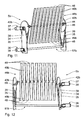
- FIGS. 9 and 10 another embodiment of the folding device 5a described. Identical parts are given the same reference numbers as in the first embodiment, to the description of which reference is hereby made. Structurally different, but functionally similar parts receive the same reference numerals with a following a.
- the main difference with respect to the first embodiment is that the side parts 42a of the frame 41a of the folding unit 81a are circular.
- the second torque-transmitting element 44 and the pin 87 are circumferentially, that is, eccentrically mounted in these circular side parts 42a.
- the electric motor 38 of the second drive means 37 is arranged in the region of the axis through the centers of the circular side parts 42a.
- a pin-shaped stop element 69 is provided on the side parts 42a. To avoid torsional forces, it is advantageous to arrange electric motors 38 and torque-transmitting elements 44 on both sides of the stand 34, that is to say on both holding elements 35.
- FIGS. 11 and 12 a third embodiment of the folding device 5b described. Identical parts are given the same reference numerals as in the preceding embodiments, to the description of which reference is hereby made. Structurally different, but functionally similar parts receive the same reference numerals with a trailing b.
- the main difference with respect to the second embodiment is that the engagement element 46b of the folding unit 81b is formed symmetrically with respect to the second axis 86.
- the second torque-transmitting element 44 is preferably formed in this embodiment as a second folding device shaft.
- the finger-shaped projections 49b each extend from the second folding device shaft 44 in opposite directions. The engagement element 46b is thus formed symmetrically to the second axis 86.
- the engagement element 46b thus has on both sides of the second axis 86 a plurality of free ends 48 which can be used for folding the corrugated cardboard web 2. This reduces the required for folding the corrugated web 2 pivoting circumference of the engagement element 46b. As a result, in particular the for reducing the time required to return the engagement member 46b to the home position, and thus reducing the time between two folding operations.
- FIGS. 13 and 14 A fourth embodiment of the folding device 5c is described. Identical parts are given the same reference numerals as in the first embodiment, the description of which is hereby incorporated by reference. Structurally different, but functionally similar parts receive the same reference numerals with a c followed.
- the main difference with respect to the first embodiment is that the folding unit 81c has only a single folding device shaft 40c for pivoting the engagement element 46c in the stand 34.
- the engagement element 46c thus has only one rotational degree of freedom.
- the engagement element 46c thus has an additional degree of translational freedom.
- the finger-shaped extensions 49 c each have two free ends 48.
- the free ends 48 are each flattened. They are therefore advantageously used on both sides.
- the length L F of the finger-shaped extensions 49c is arbitrary.
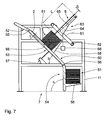
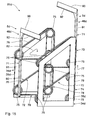
- FIG. 15 a fifth embodiment of the folding device 5d described. Identical parts are given the same reference numerals as in the first embodiment the description of which is hereby incorporated by reference. Structurally different, but functionally similar parts receive the same reference numerals with a d followed.
- two engagement elements 46d in the stand 34d of the folding unit 81 d are mounted displaceably parallel.
- the engagement member 46d each includes an L-shaped guide arm 71.
- the L-shaped arm 71 has two legs 91, 92 perpendicular to each other.
- the first leg 91 serves to support the L-shaped arm 71 in the stand 34d, while the second leg 92 forms the support edge 90.
- the guide arm 71 is slidably connected to one of the support members 35d of the stand 34d by a belt system 72, respectively.
- the holding elements 35d of the stand 34d are trapezoidal. They are preferably formed perforated and thus form only a rigid support frame. A massive and / or rectangular design of the holding elements 35d is of course also possible.
- the belt system 72 comprises an upper belt subsystem 73 and a lower belt subsystem 74.
- the lower belt subsystem 74 includes three rollers 75 on each of the support members 35d. A belt 76 is guided over the rollers 75, respectively.
- the rollers 75 are rotatably mounted on the stand 34d. At least one of the rollers 75 on each of the holding members 35d is rotatably drivable. In particular, the rollers 75 on the two holding elements 35d of the lower belt subsystem 74 are synchronized with each other.
- drive means 36 is provided to drive the rollers 75 is in the Fig. 15 not shown.
- the drive speed of the lower belt subsystem 74 is the same as that of the upper belt subsystem 73.
- the belt subsystems 73, 74 are preferably driven synchronized. Its drive speed can be adapted to the feed speed of the corrugated web 2.
- the lower belt subsystem 74 includes a vertical portion 78, a horizontal portion 79, and a diagonal portion 80.
- the upper belt subsystem 73 is offset parallel to the lower belt subsystem 74 in an offset direction 77, particularly in the vertical direction. It is at least largely identical to the lower band subsystem 74, to the description of which reference is hereby made.
- the guide arm 71 is connected in two places with one of the bands 76 of the upper band-part system 73 and one of the bands 76 of the lower band subsystem 74.
- each guide arm 71 is connected to one of the support members 35d at vertically superimposed points via the upper and lower belt subsystems 73, 74, respectively.
- He is characterized tilt-safe, parallel-displaceable mounted in the tripod 34 d.
- connection points between the guide arm 71 and the belt system 72 are aligned such that the engagement element 46d is oriented parallel to the offset direction 77.
- the engagement member 46d is cyclically slidable along the vertical portion 78, the horizontal portion 79 and the diagonal portion 80 in a first rotational direction 82 by means of the belt system 72.
- the folding unit 81 d is arranged such that the support edge 90 during displacement of the engagement element 46 d along the Horizontal section 79 is slightly below the corrugated cardboard web 2, in particular slightly below the support surface 32.
- the folding device 5d may have a second folding unit 81d, which is arranged above the corrugated cardboard web 2.
- the second folding unit 81d is mirror-symmetrical to the folding unit 8 1 d, which is referred to below as the first folding unit 81d, built on.
- the plane of symmetry runs horizontally.
- the second folding unit 81 d is arranged above the corrugated cardboard web 2, that the support edge 90 is located in its lowest point just above the support surface 32 and the corrugated cardboard web 2 presses against the same.
- the second folding unit 81 d is vertically adjustable in the vertical direction.
- the second folding unit 81d is at least slightly offset in the conveying direction 3 of the corrugated cardboard web 2 against the first folding unit 81d. In particular, it is arranged downstream of the first folding unit 81d thereon.
- an overlapping arrangement of the folding units 81 d may be advantageous because it leads to an improved folding of the corrugated cardboard web 2.
- the belt systems 72 of the folding units 81d are synchronized with each other.
- the support edge 90 of the engagement element 46d of the first folding unit 81d is engaged from below with one of the folds 20 in the corrugated cardboard web 2. In this case, it is ensured by means of a suitable control device that the support edge 90 engages in each case with one of the folds 20.
- the engagement member 46d along the diagonal portion 80 by means of the belt system 72 is displaced parallel to the support surface 32 in parallel.
- the corrugated cardboard web 2 is raised and folded down in the region of the fold 20, which rests on the support edge 90.
- the engaging member 46d of the second folding unit 81d is slid down obliquely along the diagonal portion 80.
- the support edge 90 comes with the fold 20 in the corrugated cardboard web 2, which is downstream of the fold 20, which rests on the support edge 90 of the first folding unit 81 d in engagement, and thereby ensure that this rests on the support surface 32.
- the corrugated board web 2 is folded neatly along the fold 20, in each case alternately upwards and downwards.
Landscapes
- Folding Of Thin Sheet-Like Materials, Special Discharging Devices, And Others (AREA)
- Making Paper Articles (AREA)
Applications Claiming Priority (1)
| Application Number | Priority Date | Filing Date | Title |
|---|---|---|---|
| DE102008025890A DE102008025890A1 (de) | 2008-05-29 | 2008-05-29 | Kontinuierlicher Faltprozess |
Publications (3)
| Publication Number | Publication Date |
|---|---|
| EP2128070A2 true EP2128070A2 (fr) | 2009-12-02 |
| EP2128070A3 EP2128070A3 (fr) | 2010-07-07 |
| EP2128070B1 EP2128070B1 (fr) | 2018-12-05 |
Family
ID=41009897
Family Applications (1)
| Application Number | Title | Priority Date | Filing Date |
|---|---|---|---|
| EP09006953.5A Not-in-force EP2128070B1 (fr) | 2008-05-29 | 2009-05-25 | Processus de pliage continu |
Country Status (4)
| Country | Link |
|---|---|
| US (1) | US9290354B2 (fr) |
| EP (1) | EP2128070B1 (fr) |
| DE (1) | DE102008025890A1 (fr) |
| ES (1) | ES2712197T3 (fr) |
Families Citing this family (5)
| Publication number | Priority date | Publication date | Assignee | Title |
|---|---|---|---|---|
| US8931618B2 (en) | 2011-02-08 | 2015-01-13 | C.G. Bretting Manufacturing Co., Inc. | Small and bulk pack napkin separator |
| US9371209B2 (en) | 2012-05-01 | 2016-06-21 | C.G. Bretting Manufacturing Co., Inc. | Single path single web single-fold interfolder and methods |
| DE102015116720B4 (de) * | 2015-10-01 | 2019-03-07 | Deutsche Post Ag | Verfahren und Vorrichtung zum Fördern von Stückgütern von einem Stapel oder Haufen |
| US10449746B2 (en) | 2016-06-27 | 2019-10-22 | C. G. Bretting Manufacturing Co., Inc. | Web processing system with multiple folding arrangements fed by a single web handling arrangement |
| CN107364188B (zh) * | 2017-07-27 | 2023-04-28 | 寻乌县天源包装有限公司 | 一种高强度竖瓦楞纸板的连续生产系统 |
Citations (5)
| Publication number | Priority date | Publication date | Assignee | Title |
|---|---|---|---|---|
| US2657044A (en) | 1949-03-18 | 1953-10-27 | Seaboard Container Corp | Apparatus for handling corrugated paperboard |
| US3826348A (en) | 1971-09-17 | 1974-07-30 | Bobst Fils Sa J | Article selection and separation apparatus |
| US4210318A (en) | 1978-05-24 | 1980-07-01 | Ga-Vehren Engineering Company | Fan folding and stacking device |
| DE3202176A1 (de) | 1981-02-25 | 1982-10-14 | VEB Metallwaren Delitzsch, DDR 7270 Delitzsch | Bueroheftgeraet |
| US4416653A (en) | 1981-11-23 | 1983-11-22 | International Business Machines Corporation | Apparatus for stacking fan-folded paper |
Family Cites Families (25)
| Publication number | Priority date | Publication date | Assignee | Title |
|---|---|---|---|---|
| US3127029A (en) * | 1964-03-31 | Device for separating individual groups of flat articles | ||
| US2729445A (en) * | 1952-11-05 | 1956-01-03 | William M Webster | Spiral paper folding device |
| US2815205A (en) * | 1956-09-05 | 1957-12-03 | Russell A Engstrom | Paper folding and creasing machine |
| US3544099A (en) * | 1968-12-23 | 1970-12-01 | Eastman Kodak Co | Method and apparatus for continuous zig-zag web folding |
| US3640521A (en) * | 1969-08-18 | 1972-02-08 | Advanced Terminals Inc | Apparatus for stacking fan folded paper |
| US4268341A (en) * | 1978-03-15 | 1981-05-19 | S&S Corrugated Paper Machinery Co. Inc. | Zero waste order change system for a corrugator |
| JPS59114263A (ja) * | 1982-12-17 | 1984-07-02 | Matsushita Electric Ind Co Ltd | つづら折り箱詰装置 |
| DE3502176A1 (de) * | 1985-01-23 | 1986-07-24 | Bielomatik Leuze Gmbh + Co, 7442 Neuffen | Vorrichtung zum falzen von materialbahnen |
| US4721295A (en) * | 1986-08-12 | 1988-01-26 | Kimberly-Clark Corporation | Apparatus and process for separating stacks of sheets into bundles |
| US4700939A (en) * | 1986-08-12 | 1987-10-20 | Kimberly-Clark Corporation | Apparatus and process for separating and removing bundles of sheets |
| US4846454A (en) * | 1988-02-22 | 1989-07-11 | Th Stralfors Ab | Method and apparatus for folding, stacking and separating continuous forms in a moving web |
| US5201700A (en) * | 1988-11-07 | 1993-04-13 | Industria Grafica Meschi S.R.L. | Method for folding material fed from a continuous band into accordion-like manner at a high speed |
| DE3927422C2 (de) * | 1989-08-19 | 1998-07-09 | Winkler Duennebier Kg Masch | Verfahren und Vorrichtung zur Herstellung von zahlgerechten Teilstapeln aus überlappend ineinandergefalteten Tüchern |
| DE4305158C3 (de) | 1993-02-19 | 2003-10-30 | Bhs Corr Masch & Anlagenbau | Wellpappenmaschine zur Herstellung einseitiger Wellpappe |
| DE4419989C2 (de) * | 1994-06-08 | 1997-10-02 | Winkler Duennebier Kg Masch | Verfahren und Vorrichtung zum Stapeln von gefalteten Tüchern |
| DE4425155A1 (de) * | 1994-07-16 | 1996-01-18 | Bhs Corr Masch & Anlagenbau | Anlage zur Herstellung von Wellpappebögen mit veränderbarem Format |
| DE19538519C2 (de) * | 1995-10-05 | 1997-09-11 | Rabofsky Karl Gmbh | Messerfaltmaschine |
| US6336307B1 (en) * | 1997-10-09 | 2002-01-08 | Eki Holding Corporation | Method of packaging a strip of material for use in cutting into sheet elements arranged end to end |
| US6254522B1 (en) * | 1999-10-05 | 2001-07-03 | C. G. Bretting Manufacturing Co., Inc. | Separator finger apparatus |
| DE10252918A1 (de) * | 2002-11-12 | 2004-05-27 | Kappa Sieger Gmbh | Vorrichtung und Verfahren zum Umlenken einer Materialbahn |
| DE10312600A1 (de) | 2003-03-21 | 2004-10-07 | Bhs Corrugated Maschinen- Und Anlagenbau Gmbh | Wellpappe-Anlage sowie Verfahren zur Herstellung von Wellpappe-Bögen |
| DE102004025501B4 (de) * | 2004-05-21 | 2007-07-05 | Karl Rabofsky Gmbh | Verfahren zum Herstellen von Stehfalten und Messerfaltmaschine mit Fördereinrichtung |
| US7303524B2 (en) * | 2005-07-14 | 2007-12-04 | First Data Corporation | Folder unit for processing sheet-like materials |
| ITBO20070304A1 (it) * | 2007-04-24 | 2008-10-25 | Maurizio Bellucci | Dispositivo di guida per cartone a modulo continuo |
| DE102007049422A1 (de) | 2007-10-12 | 2009-04-16 | Bhs Corrugated Maschinen- Und Anlagenbau Gmbh | Waben-Wellpappen-Anlage |
-
2008
- 2008-05-29 DE DE102008025890A patent/DE102008025890A1/de not_active Ceased
-
2009
- 2009-05-25 ES ES09006953T patent/ES2712197T3/es active Active
- 2009-05-25 EP EP09006953.5A patent/EP2128070B1/fr not_active Not-in-force
- 2009-05-28 US US12/473,614 patent/US9290354B2/en not_active Expired - Fee Related
Patent Citations (5)
| Publication number | Priority date | Publication date | Assignee | Title |
|---|---|---|---|---|
| US2657044A (en) | 1949-03-18 | 1953-10-27 | Seaboard Container Corp | Apparatus for handling corrugated paperboard |
| US3826348A (en) | 1971-09-17 | 1974-07-30 | Bobst Fils Sa J | Article selection and separation apparatus |
| US4210318A (en) | 1978-05-24 | 1980-07-01 | Ga-Vehren Engineering Company | Fan folding and stacking device |
| DE3202176A1 (de) | 1981-02-25 | 1982-10-14 | VEB Metallwaren Delitzsch, DDR 7270 Delitzsch | Bueroheftgeraet |
| US4416653A (en) | 1981-11-23 | 1983-11-22 | International Business Machines Corporation | Apparatus for stacking fan-folded paper |
Also Published As
| Publication number | Publication date |
|---|---|
| EP2128070A3 (fr) | 2010-07-07 |
| US9290354B2 (en) | 2016-03-22 |
| EP2128070B1 (fr) | 2018-12-05 |
| US20090298661A1 (en) | 2009-12-03 |
| DE102008025890A1 (de) | 2009-12-24 |
| ES2712197T3 (es) | 2019-05-09 |
Similar Documents
| Publication | Publication Date | Title |
|---|---|---|
| DE2264633A1 (de) | Vorrichtung zum falzen und schneiden duennen streifenmaterials | |
| EP2988885A1 (fr) | Dresseuse à réglage individuel et dispositif de changement d'outil | |
| DE3836214C2 (fr) | ||
| EP2128070B1 (fr) | Processus de pliage continu | |
| EP2128069B1 (fr) | Dispositif de pliage | |
| EP0740508A1 (fr) | Dispositif pour enrouler une bande de pate | |
| EP0569887A1 (fr) | Dispositif pour assembler et brocher des produits imprimés pliés | |
| EP1382402A2 (fr) | Dispositif pour la fabrication de tubes à partir de tôles | |
| CH669130A5 (de) | Verfahren und vorrichtung zum runden von blechen, insbesondere fuer dosenkoerper. | |
| EP3006197B1 (fr) | Dispositif et procédé d'alignement de sections de matériau essentiellement plates | |
| DE19901187C2 (de) | Vorrichtung zum kontinuierlichen Walzen eines Blechbandes zu einem Profil mit im Querschnitt geraden Profilschenkeln, insbesondere zum Herstellen eines längsgeschweißten Rechteckrohres | |
| EP0872443B1 (fr) | Dispositif pour former une pile partielle s'étandant perpendiculèrement aux feuilles imprimées rangées sur la tranche et une à côté de l'autre | |
| DE3619648A1 (de) | Bindekamm-schliessvorrichtung | |
| DE102010031668A1 (de) | Falt- und Stapel-Anlage für Wellpappebahnen | |
| DE1536849B1 (de) | Vorrichtung und Verfahren zur Herstellung von gefalteten Filtereinsaetzen aus einem Filtermaterialband | |
| EP2128065A2 (fr) | Dispositif d'empilage | |
| EP1351872B1 (fr) | Dispositif pour distribuer ou recevoir des feuillets individuels | |
| DE2109216C3 (de) | Vorrichtung zur Herstellung von Formlöchern in einer Materialbahn, z.B. von Streckmetall | |
| DE1452923A1 (de) | Vorrichtung zum Falten oder zum Anbringen von Vertiefungen od.dgl. in tafelfoermigen Werkstoffen | |
| DE2451469A1 (de) | Verfahren und vorrichtung zum falten von bogen aus papier oder dergleichen | |
| EP2316767B1 (fr) | Dispositif et procédé de fabrication de piles de produits d'impression | |
| DE4024034C2 (de) | Druckgerät, insbesondere Tischstempelgerät | |
| DE1959881A1 (de) | Verfahren und Maschine zur vollautomatischen Herstellung von Federstiften mit wellenfoermigem Laengsschlitz | |
| EP0082537A1 (fr) | Procédé de fabrication de paquets de tôles et dispositif pour sa mise en oeuvre | |
| DE2509519A1 (de) | Verfahren und vorrichtung zum vorschieben von aufeinanderfolgenden gegenstaenden, insbesondere von zu bearbeitenden papierstapeln |
Legal Events
| Date | Code | Title | Description |
|---|---|---|---|
| PUAI | Public reference made under article 153(3) epc to a published international application that has entered the european phase |
Free format text: ORIGINAL CODE: 0009012 |
|
| AK | Designated contracting states |
Kind code of ref document: A2 Designated state(s): AT BE BG CH CY CZ DE DK EE ES FI FR GB GR HR HU IE IS IT LI LT LU LV MC MK MT NL NO PL PT RO SE SI SK TR |
|
| PUAL | Search report despatched |
Free format text: ORIGINAL CODE: 0009013 |
|
| AK | Designated contracting states |
Kind code of ref document: A3 Designated state(s): AT BE BG CH CY CZ DE DK EE ES FI FR GB GR HR HU IE IS IT LI LT LU LV MC MK MT NL NO PL PT RO SE SI SK TR |
|
| AX | Request for extension of the european patent |
Extension state: AL BA RS |
|
| 17P | Request for examination filed |
Effective date: 20100917 |
|
| 17Q | First examination report despatched |
Effective date: 20110401 |
|
| GRAP | Despatch of communication of intention to grant a patent |
Free format text: ORIGINAL CODE: EPIDOSNIGR1 |
|
| STAA | Information on the status of an ep patent application or granted ep patent |
Free format text: STATUS: GRANT OF PATENT IS INTENDED |
|
| INTG | Intention to grant announced |
Effective date: 20180709 |
|
| GRAS | Grant fee paid |
Free format text: ORIGINAL CODE: EPIDOSNIGR3 |
|
| GRAA | (expected) grant |
Free format text: ORIGINAL CODE: 0009210 |
|
| GRAA | (expected) grant |
Free format text: ORIGINAL CODE: 0009210 |
|
| STAA | Information on the status of an ep patent application or granted ep patent |
Free format text: STATUS: THE PATENT HAS BEEN GRANTED |
|
| AK | Designated contracting states |
Kind code of ref document: B1 Designated state(s): AT BE BG CH CY CZ DE DK EE ES FI FR GB GR HR HU IE IS IT LI LT LU LV MC MK MT NL NO PL PT RO SE SI SK TR |
|
| REG | Reference to a national code |
Ref country code: GB Ref legal event code: FG4D Free format text: NOT ENGLISH |
|
| REG | Reference to a national code |
Ref country code: CH Ref legal event code: EP |
|
| REG | Reference to a national code |
Ref country code: AT Ref legal event code: REF Ref document number: 1072781 Country of ref document: AT Kind code of ref document: T Effective date: 20181215 |
|
| REG | Reference to a national code |
Ref country code: IE Ref legal event code: FG4D Free format text: LANGUAGE OF EP DOCUMENT: GERMAN |
|
| REG | Reference to a national code |
Ref country code: DE Ref legal event code: R096 Ref document number: 502009015485 Country of ref document: DE |
|
| REG | Reference to a national code |
Ref country code: NL Ref legal event code: MP Effective date: 20181205 |
|
| REG | Reference to a national code |
Ref country code: LT Ref legal event code: MG4D |
|
| PG25 | Lapsed in a contracting state [announced via postgrant information from national office to epo] |
Ref country code: LV Free format text: LAPSE BECAUSE OF FAILURE TO SUBMIT A TRANSLATION OF THE DESCRIPTION OR TO PAY THE FEE WITHIN THE PRESCRIBED TIME-LIMIT Effective date: 20181205 Ref country code: HR Free format text: LAPSE BECAUSE OF FAILURE TO SUBMIT A TRANSLATION OF THE DESCRIPTION OR TO PAY THE FEE WITHIN THE PRESCRIBED TIME-LIMIT Effective date: 20181205 Ref country code: FI Free format text: LAPSE BECAUSE OF FAILURE TO SUBMIT A TRANSLATION OF THE DESCRIPTION OR TO PAY THE FEE WITHIN THE PRESCRIBED TIME-LIMIT Effective date: 20181205 Ref country code: BG Free format text: LAPSE BECAUSE OF FAILURE TO SUBMIT A TRANSLATION OF THE DESCRIPTION OR TO PAY THE FEE WITHIN THE PRESCRIBED TIME-LIMIT Effective date: 20190305 Ref country code: NO Free format text: LAPSE BECAUSE OF FAILURE TO SUBMIT A TRANSLATION OF THE DESCRIPTION OR TO PAY THE FEE WITHIN THE PRESCRIBED TIME-LIMIT Effective date: 20190305 Ref country code: LT Free format text: LAPSE BECAUSE OF FAILURE TO SUBMIT A TRANSLATION OF THE DESCRIPTION OR TO PAY THE FEE WITHIN THE PRESCRIBED TIME-LIMIT Effective date: 20181205 |
|
| REG | Reference to a national code |
Ref country code: ES Ref legal event code: FG2A Ref document number: 2712197 Country of ref document: ES Kind code of ref document: T3 Effective date: 20190509 |
|
| PG25 | Lapsed in a contracting state [announced via postgrant information from national office to epo] |
Ref country code: GR Free format text: LAPSE BECAUSE OF FAILURE TO SUBMIT A TRANSLATION OF THE DESCRIPTION OR TO PAY THE FEE WITHIN THE PRESCRIBED TIME-LIMIT Effective date: 20190306 Ref country code: SE Free format text: LAPSE BECAUSE OF FAILURE TO SUBMIT A TRANSLATION OF THE DESCRIPTION OR TO PAY THE FEE WITHIN THE PRESCRIBED TIME-LIMIT Effective date: 20181205 |
|
| PG25 | Lapsed in a contracting state [announced via postgrant information from national office to epo] |
Ref country code: NL Free format text: LAPSE BECAUSE OF FAILURE TO SUBMIT A TRANSLATION OF THE DESCRIPTION OR TO PAY THE FEE WITHIN THE PRESCRIBED TIME-LIMIT Effective date: 20181205 |
|
| PG25 | Lapsed in a contracting state [announced via postgrant information from national office to epo] |
Ref country code: PL Free format text: LAPSE BECAUSE OF FAILURE TO SUBMIT A TRANSLATION OF THE DESCRIPTION OR TO PAY THE FEE WITHIN THE PRESCRIBED TIME-LIMIT Effective date: 20181205 Ref country code: PT Free format text: LAPSE BECAUSE OF FAILURE TO SUBMIT A TRANSLATION OF THE DESCRIPTION OR TO PAY THE FEE WITHIN THE PRESCRIBED TIME-LIMIT Effective date: 20190405 Ref country code: CZ Free format text: LAPSE BECAUSE OF FAILURE TO SUBMIT A TRANSLATION OF THE DESCRIPTION OR TO PAY THE FEE WITHIN THE PRESCRIBED TIME-LIMIT Effective date: 20181205 |
|
| PG25 | Lapsed in a contracting state [announced via postgrant information from national office to epo] |
Ref country code: SK Free format text: LAPSE BECAUSE OF FAILURE TO SUBMIT A TRANSLATION OF THE DESCRIPTION OR TO PAY THE FEE WITHIN THE PRESCRIBED TIME-LIMIT Effective date: 20181205 Ref country code: EE Free format text: LAPSE BECAUSE OF FAILURE TO SUBMIT A TRANSLATION OF THE DESCRIPTION OR TO PAY THE FEE WITHIN THE PRESCRIBED TIME-LIMIT Effective date: 20181205 Ref country code: IS Free format text: LAPSE BECAUSE OF FAILURE TO SUBMIT A TRANSLATION OF THE DESCRIPTION OR TO PAY THE FEE WITHIN THE PRESCRIBED TIME-LIMIT Effective date: 20190405 Ref country code: RO Free format text: LAPSE BECAUSE OF FAILURE TO SUBMIT A TRANSLATION OF THE DESCRIPTION OR TO PAY THE FEE WITHIN THE PRESCRIBED TIME-LIMIT Effective date: 20181205 |
|
| REG | Reference to a national code |
Ref country code: DE Ref legal event code: R097 Ref document number: 502009015485 Country of ref document: DE |
|
| PLBE | No opposition filed within time limit |
Free format text: ORIGINAL CODE: 0009261 |
|
| STAA | Information on the status of an ep patent application or granted ep patent |
Free format text: STATUS: NO OPPOSITION FILED WITHIN TIME LIMIT |
|
| PG25 | Lapsed in a contracting state [announced via postgrant information from national office to epo] |
Ref country code: SI Free format text: LAPSE BECAUSE OF FAILURE TO SUBMIT A TRANSLATION OF THE DESCRIPTION OR TO PAY THE FEE WITHIN THE PRESCRIBED TIME-LIMIT Effective date: 20181205 Ref country code: DK Free format text: LAPSE BECAUSE OF FAILURE TO SUBMIT A TRANSLATION OF THE DESCRIPTION OR TO PAY THE FEE WITHIN THE PRESCRIBED TIME-LIMIT Effective date: 20181205 |
|
| 26N | No opposition filed |
Effective date: 20190906 |
|
| REG | Reference to a national code |
Ref country code: CH Ref legal event code: PL |
|
| PG25 | Lapsed in a contracting state [announced via postgrant information from national office to epo] |
Ref country code: CH Free format text: LAPSE BECAUSE OF NON-PAYMENT OF DUE FEES Effective date: 20190531 Ref country code: LI Free format text: LAPSE BECAUSE OF NON-PAYMENT OF DUE FEES Effective date: 20190531 Ref country code: MC Free format text: LAPSE BECAUSE OF FAILURE TO SUBMIT A TRANSLATION OF THE DESCRIPTION OR TO PAY THE FEE WITHIN THE PRESCRIBED TIME-LIMIT Effective date: 20181205 |
|
| REG | Reference to a national code |
Ref country code: BE Ref legal event code: MM Effective date: 20190531 |
|
| PG25 | Lapsed in a contracting state [announced via postgrant information from national office to epo] |
Ref country code: LU Free format text: LAPSE BECAUSE OF NON-PAYMENT OF DUE FEES Effective date: 20190525 |
|
| PG25 | Lapsed in a contracting state [announced via postgrant information from national office to epo] |
Ref country code: TR Free format text: LAPSE BECAUSE OF FAILURE TO SUBMIT A TRANSLATION OF THE DESCRIPTION OR TO PAY THE FEE WITHIN THE PRESCRIBED TIME-LIMIT Effective date: 20181205 |
|
| PG25 | Lapsed in a contracting state [announced via postgrant information from national office to epo] |
Ref country code: IE Free format text: LAPSE BECAUSE OF NON-PAYMENT OF DUE FEES Effective date: 20190525 |
|
| PG25 | Lapsed in a contracting state [announced via postgrant information from national office to epo] |
Ref country code: BE Free format text: LAPSE BECAUSE OF NON-PAYMENT OF DUE FEES Effective date: 20190531 |
|
| REG | Reference to a national code |
Ref country code: AT Ref legal event code: MM01 Ref document number: 1072781 Country of ref document: AT Kind code of ref document: T Effective date: 20190525 |
|
| PG25 | Lapsed in a contracting state [announced via postgrant information from national office to epo] |
Ref country code: AT Free format text: LAPSE BECAUSE OF NON-PAYMENT OF DUE FEES Effective date: 20190525 |
|
| PG25 | Lapsed in a contracting state [announced via postgrant information from national office to epo] |
Ref country code: CY Free format text: LAPSE BECAUSE OF FAILURE TO SUBMIT A TRANSLATION OF THE DESCRIPTION OR TO PAY THE FEE WITHIN THE PRESCRIBED TIME-LIMIT Effective date: 20181205 |
|
| PG25 | Lapsed in a contracting state [announced via postgrant information from national office to epo] |
Ref country code: HU Free format text: LAPSE BECAUSE OF FAILURE TO SUBMIT A TRANSLATION OF THE DESCRIPTION OR TO PAY THE FEE WITHIN THE PRESCRIBED TIME-LIMIT; INVALID AB INITIO Effective date: 20090525 Ref country code: MT Free format text: LAPSE BECAUSE OF FAILURE TO SUBMIT A TRANSLATION OF THE DESCRIPTION OR TO PAY THE FEE WITHIN THE PRESCRIBED TIME-LIMIT Effective date: 20181205 |
|
| PGFP | Annual fee paid to national office [announced via postgrant information from national office to epo] |
Ref country code: FR Payment date: 20210521 Year of fee payment: 13 Ref country code: IT Payment date: 20210531 Year of fee payment: 13 |
|
| PGFP | Annual fee paid to national office [announced via postgrant information from national office to epo] |
Ref country code: GB Payment date: 20210526 Year of fee payment: 13 Ref country code: ES Payment date: 20210618 Year of fee payment: 13 |
|
| PGFP | Annual fee paid to national office [announced via postgrant information from national office to epo] |
Ref country code: DE Payment date: 20210723 Year of fee payment: 13 |
|
| PG25 | Lapsed in a contracting state [announced via postgrant information from national office to epo] |
Ref country code: MK Free format text: LAPSE BECAUSE OF FAILURE TO SUBMIT A TRANSLATION OF THE DESCRIPTION OR TO PAY THE FEE WITHIN THE PRESCRIBED TIME-LIMIT Effective date: 20181205 |
|
| REG | Reference to a national code |
Ref country code: DE Ref legal event code: R119 Ref document number: 502009015485 Country of ref document: DE |
|
| GBPC | Gb: european patent ceased through non-payment of renewal fee |
Effective date: 20220525 |
|
| PG25 | Lapsed in a contracting state [announced via postgrant information from national office to epo] |
Ref country code: FR Free format text: LAPSE BECAUSE OF NON-PAYMENT OF DUE FEES Effective date: 20220531 |
|
| PG25 | Lapsed in a contracting state [announced via postgrant information from national office to epo] |
Ref country code: GB Free format text: LAPSE BECAUSE OF NON-PAYMENT OF DUE FEES Effective date: 20220525 Ref country code: DE Free format text: LAPSE BECAUSE OF NON-PAYMENT OF DUE FEES Effective date: 20221201 |
|
| REG | Reference to a national code |
Ref country code: ES Ref legal event code: FD2A Effective date: 20230630 |
|
| P01 | Opt-out of the competence of the unified patent court (upc) registered |
Effective date: 20230527 |
|
| PG25 | Lapsed in a contracting state [announced via postgrant information from national office to epo] |
Ref country code: IT Free format text: LAPSE BECAUSE OF NON-PAYMENT OF DUE FEES Effective date: 20220525 Ref country code: ES Free format text: LAPSE BECAUSE OF NON-PAYMENT OF DUE FEES Effective date: 20220526 |