EP2128228A1 - Verfahren zur herstellung, zur aufbewahrung und zum transport für gashydrat - Google Patents
Verfahren zur herstellung, zur aufbewahrung und zum transport für gashydrat Download PDFInfo
- Publication number
- EP2128228A1 EP2128228A1 EP07714511A EP07714511A EP2128228A1 EP 2128228 A1 EP2128228 A1 EP 2128228A1 EP 07714511 A EP07714511 A EP 07714511A EP 07714511 A EP07714511 A EP 07714511A EP 2128228 A1 EP2128228 A1 EP 2128228A1
- Authority
- EP
- European Patent Office
- Prior art keywords
- slurry
- pellets
- tank
- mother liquid
- storage tank
- Prior art date
- Legal status (The legal status is an assumption and is not a legal conclusion. Google has not performed a legal analysis and makes no representation as to the accuracy of the status listed.)
- Withdrawn
Links
Images


Classifications
-
- C—CHEMISTRY; METALLURGY
- C10—PETROLEUM, GAS OR COKE INDUSTRIES; TECHNICAL GASES CONTAINING CARBON MONOXIDE; FUELS; LUBRICANTS; PEAT
- C10L—FUELS NOT OTHERWISE PROVIDED FOR; NATURAL GAS; SYNTHETIC NATURAL GAS OBTAINED BY PROCESSES NOT COVERED BY SUBCLASSES C10G OR C10K; LIQUIFIED PETROLEUM GAS; USE OF ADDITIVES TO FUELS OR FIRES; FIRE-LIGHTERS
- C10L3/00—Gaseous fuels; Natural gas; Synthetic natural gas obtained by processes not covered by subclass C10G, C10K; Liquefied petroleum gas
- C10L3/06—Natural gas; Synthetic natural gas obtained by processes not covered by C10G, C10K3/02 or C10K3/04
- C10L3/10—Working-up natural gas or synthetic natural gas
- C10L3/108—Production of gas hydrates
-
- C—CHEMISTRY; METALLURGY
- C10—PETROLEUM, GAS OR COKE INDUSTRIES; TECHNICAL GASES CONTAINING CARBON MONOXIDE; FUELS; LUBRICANTS; PEAT
- C10L—FUELS NOT OTHERWISE PROVIDED FOR; NATURAL GAS; SYNTHETIC NATURAL GAS OBTAINED BY PROCESSES NOT COVERED BY SUBCLASSES C10G OR C10K; LIQUIFIED PETROLEUM GAS; USE OF ADDITIVES TO FUELS OR FIRES; FIRE-LIGHTERS
- C10L5/00—Solid fuels
- C10L5/02—Solid fuels such as briquettes consisting mainly of carbonaceous materials of mineral or non-mineral origin
- C10L5/34—Other details of the shaped fuels, e.g. briquettes
- C10L5/36—Shape
- C10L5/363—Pellets or granulates
-
- C—CHEMISTRY; METALLURGY
- C10—PETROLEUM, GAS OR COKE INDUSTRIES; TECHNICAL GASES CONTAINING CARBON MONOXIDE; FUELS; LUBRICANTS; PEAT
- C10L—FUELS NOT OTHERWISE PROVIDED FOR; NATURAL GAS; SYNTHETIC NATURAL GAS OBTAINED BY PROCESSES NOT COVERED BY SUBCLASSES C10G OR C10K; LIQUIFIED PETROLEUM GAS; USE OF ADDITIVES TO FUELS OR FIRES; FIRE-LIGHTERS
- C10L5/00—Solid fuels
- C10L5/02—Solid fuels such as briquettes consisting mainly of carbonaceous materials of mineral or non-mineral origin
- C10L5/34—Other details of the shaped fuels, e.g. briquettes
- C10L5/36—Shape
- C10L5/366—Powders
Definitions
- the present invention relates to a method for producing, storing, and transporting gas hydrate, and more specifically to a method for producing gas hydrate through molding a powdery gas hydrate into pellets thereof using a granulation apparatus in a non-reacted gas and through carrying out the pellets to a storage tank under atmospheric pressure, to a method for storing the gas hydrate by storing said pellets in the storage tank, and to a method for transporting the gas hydrate in the storage tank.
- the hydrate of natural gas, or gas hydrate On transporting natural gas after being hydrated, however, the hydrate of natural gas, or gas hydrate, has a low filling rate in as powder state, (filling rate of 0.4, for example), and gives poor handling performance. Consequently, there are necessities to increase the filling rate and to increase the handling performance.
- the filling rate increases (filling rate of 0.56, for example). Since, however, the granulation apparatus is filled with a portion of non-reacted gas in the gas hydrate production apparatus, when the pellets formed by the granulation apparatus are carried out to a storage tank set under atmospheric pressure, the high-pressure non-reacted gas enters the storage tank together with the pellets. Thus, the storage tank is required to be fabricated to endure high pressure.
- the storage tank expects the one having large capacity, such as a tank having 60 to 70 m in diameter and 20 to 30 m in height.
- the cost becomes excessive, which causes loss of advantages of producing, storing, and transporting the gas hydrate of natural gas and water. Therefore, further technology innovation is required in order to store the pellets molded by a granulation apparatus in a storage tank under atmospheric pressure without accompanying high pressure non-reacted gas.
- pellets on storing pellets, when the pellets are charged from the upper part of the storage tank, they may collide with the bottom of the storage tank or with other pellets accumulated in the tank, which may break or disrupt pellets. Break or disruption of pellets deteriorates the self-retaining effect, and likely induces gasification. If pellet debris gets mixed into the slurry mother liquid, the slurry mother liquid becomes sherbet state, which makes the adjustment of pellet mixing rate difficult on transporting the pellets. When the pellets are discharged from a storage tank for loading on a ship, the carry-out of the pellets may become difficult as the pellets in the storage tank are consolidated.
- the present invention has been implemented in order to solve the above problems, and an object of the present invention is to provide a method for producing gas hydrate by discharging pellets in a non-reacted gas to a storage tank set under atmospheric pressure without accompanying the non-reacted gas. Another object of the present invention is to provide a method for storing gas hydrate, preventing damage to pellets on charging the pellets to the storage tank. Further object of the present invention is to provide a method for transporting gas hydrate, smoothly discharging the pellets on discharging them from the storage tank.
- the invention in claim 1 is a method for producing gas hydrate through molding a powdery gas hydrate into pellets thereof using a granulation apparatus in a non-reacted gas, then the pellets being carried out to a storage tank under atmospheric pressure, the method having the steps of: charging the non-reacted gas into a slurry tank; charging the pellets into the slurry tank filled with the non-reacted gas; charging a slurry mother liquid into the slurry tank holding the charged pellets to return the non-reacted gas in the slurry tank to the granulation apparatus; manipulating a valve of a slurry transfer pipe attached to the slurry tank to release internal pressure of the slurry tank; and charging the depressurized non-reacted gas into the slurry tank after releasing the internal pressure, pushing the pellets in the slurry tank into the slurry transfer pipe together with the slurry mother liquid , and simultaneously supplying the slurry mother liquid to said slurry tank to
- the invention in claim 2 is a method for producing gas hydrate through molding a powdery gas hydrate into pellets thereof using a granulation apparatus in a non-reacting gas, which pellets then being carried out to a storage tank under atmospheric pressure, the method having the steps of: charging the pellets into a slurry mother liquid in the non-reacted gas to form a slurry; charging the slurry into a slurry tank to return the non-reacted gas in the slurry tank to the granulation apparatus; manipulating a valve of a slurry transfer pipe attached to the slurry tank to release internal pressure of the slurry tank; and charging the depressurized non-reacted gas into the slurry tank after releasing the internal pressure, pushing the pellet in the slurry tank into the slurry transfer pipe together with the slurry mother liquid, and simultaneously supplying the slurry mother liquid to the slurry tank to dilute the concentration of the slurry.
- the invention in claim 3 is a method for storing gas hydrate through carrying pellets formed by compression molding of a powdery gas hydrate into a storage tank through the use of a slurry mother liquid, the method having the step of charging a shock-absorbing liquid in advance into the storage tank and absorbing an shock on the pellet being charged to the storage tank by the shock-absorbing liquid.
- the invention in claim 4 is the method according to claim 3, wherein the level of the shock-absorbing liquid is maintained to a given height.
- the invention in claim 5 is the method according to claim 3, further having the step of locating pluralities of slurry-charging nozzles at the upper part of the storage tank to eject the slurry mother liquid which contains pellets therethrough in sequential order beginning from a specified nozzle.
- the invention in claim 6 is the method according to claim 3, further having the step of ejecting the slurry mother liquid which contains the pellets, in a spiral pattern, from a freely rotatable slurry-charging nozzle positioned at the upper part of the storage tank.
- the invention in claim 7 is the method for transporting gas hydrate having the steps of: charging a slurry mother liquid into the slurry storage tank, on carrying out pellets from the storage tank, to bring the pellets into a flowing state; simultaneously ejecting the slurry mother liquid against a pellet suction opening at the bottom part of the storage tank to separate the lump of pellets clogging the pellet suction opening; discharging the separated pellets through the pellet suction opening together with the slurry mother liquid; and removing excess slurry mother liquid in the step of the discharge of the pellets to adjust the concentration of the slurry.
- the invention in claim 8 is the method according to claim 7, wherein kerosene or gas oil is used as a liquid for separating and discharging the pellets.
- the invention in claim 1 is a method for carrying out the gas hydrate through molding a powdery gas hydrate into pellets thereof using a granulation apparatus in a non-reacted gas, which pellets then being carried out to a storage tank under atmospheric pressure, composed of the steps of: charging the non-reacted gas into a slurry tank; charging the pellets into the slurry tank filled with the non-reacted gas; charging a slurry mother liquid into the slurry tank holding the charged pellets to return the non-reacted gas in the slurry tank to the granulation apparatus; manipulating a valve of a slurry transfer pipe attached to the slurry tank to release the internal pressure of the slurry tank; and charging the depressurized non-reacted gas into the slurry tank after releasing the internal pressure, pushing the pellets in the slurry tank into the slurry transfer pipe together with the slurry mother liquid, and simultaneously supplying the slurry mother liquid to the slurry tank to dilute the concentration of the slurry.
- the pellets in the non-reacted gas can be smoothly carried out to a storage tank set under atmospheric pressure, without accompanying high pressure non-reacted gas.
- a large capacity tank such as that having 60 to 70 m in diameter and 20 to 30 m in height, is constructed, there is no need of pressure-resistant design and thus the cost can be significantly suppressed.
- the invention in claim 2 is a method for carrying out gas hydrate through molding a powdery gas hydrate into pellets thereof using a granulation apparatus in a non-reacted gas, which pellets then being carried out to a storage tank under atmospheric pressure, composed of the steps of: charging the pellets to a slurry mother liquid into the non-reacted gas to form a slurry; charging the slurry into a slurry tank to return the non-reacted gas in the slurry tank to the granulation apparatus; manipulating a valve of a slurry transfer pipe attached to the slurry tank to release the internal pressure of the slurry tank; and charging the depressurized non-reacted gas into the slurry tank after releasing the internal pressure, pushing the pellets in the slurry tank into the slurry transfer pipe together with the slurry mother liquid , and simultaneously supplying the slurry mother liquid to the slurry tank to dilute the concentration of the slurry. Consequently, in addition to the effect of the present invention in claim 1, the pellet
- the invention in claim 3 is a method for carrying in gas hydrate through carrying the pellets formed by compression molding of a powdery gas hydrate to a storage tank through the use of a slurry mother liquid, composed of the step of charging a shock-absorbing liquid in advance into the storage tank and thus absorbing a shock on the pellets being charged to the storage tank by the shock-absorbing liquid. Consequently, the shock on charging the pellets into the storage tank is significantly decreased, which can prevent damage and disruption of pellets. As a result, gasification of pellets caused by damage and disruption can be suppressed. In addition, since the mixing of pellet debris into the slurry mother liquid becomes less, the filling rate of pellets can be accurately adjusted during the transfer of the pellets.
- the invention in claim 4 maintains the level of the shock-absorbing liquid to a specified height. Consequently, in addition of the effect of the invention in claim 3, the pellets can be always charged under the same condition.
- the invention in claim 5 locates pluralities of slurry-charging nozzles at the upper part of the storage tank and ejects a slurry mother liquid which contains pellets therethrough in sequential order beginning from a specified nozzle. Consequently, the pellets can be accumulated almost uniformly in the storage tank.
- the invention in claim 6 ejects the slurry mother liquid which contains the pellets, in a spiral pattern, from a freely rotatable slurry-charging nozzle positioned at the upper part of the storage tank. Consequently, similar to the invention described in claim 5, the pellets can be accumulated almost uniformly in the storage tank.
- a slurry mother liquid is charged into the slurry storage tank, on carrying out the pellets from the storage tank, to bring the pellets into a flowing state, and simultaneously the slurry mother liquid is ejected against a pellet suction opening at the bottom part of the storage tank to separate a lump of pellets clogging the pellet suction opening, and then the separated pellets are discharged through the pellet suction opening together with the slurry mother liquid, and excess slurry mother liquid is removed in the step of the discharge of the pellets to adjust the concentration of the slurry. Consequently, the pellets in the storage tank can be smoothly and promptly discharged.
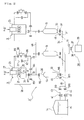
- the raw material gas (such as natural gas) in a spherical tank 1 is increased in the pressure to a specified level (for example 5.4 MPa, preferably from 5 to 7 MPa) by a pressurizing apparatus (not shown), and is cooled to a specified temperature (for example 3°C, preferably from 3°C to 10°C) by a cooler 2, and then is charged into a gas hydrate production apparatus 3.
- the water (such as plain water) w in a water storage tank 4 is cooled to a specified temperature (for example 3°C, preferably from 3°C to 10°C) by a cooler 5, and then is supplied to the gas hydrate production apparatus 3.
- the natural gas g supplied to the gas hydrate production apparatus 3 carries out hydration reaction with the water w to produce natural gas hydrate n (hereinafter referred to as the "gas hydrate").
- the heat of formation generated on producing the gas hydrate is removed by a cooling jacket 6 located outside a gas hydrate production tank.
- the gas hydrate production tank internals are agitated by an agitator 7.
- the gas hydrate n is charged into a dehydrator, for example a dehydrator 8 of screw-press type, together with the non-reacted water.
- the gas hydrate n dewatered by the dehydrator 8 is molded into a solid having a shape and a size suitable for transportation and storage, (hereinafter referred to as the "pellets") by a pelletizer 9, (hereinafter referred to as the "granulation apparatus").
- the shape of pellets includes spherical shape and convex lens shape.
- the size of pellets is preferably about 20 mm in diameter or in diameter of inscribed circle, (hereinafter referred to simply as the "diameter").
- the diameter is not specifically limited to the range, and for example, about 10 mm to 100 mm can be applied.
- the pellets may have the same size as each other, different pellet diameters can further increase the filling rate. In that regard, it is preferred that the large pellet has a diameter of about 20 to 100 mm, and that the small pellet has a diameter of about 10 to 40 mm.
- the pellets p formed by the granulation apparatus 9 are cooled to a specified temperature (for example, ranging from -15°C to -30°C) by a cooler 10, for example the cooler 10 of screw-conveyer type, composed of a horizontal casing 11 provided with a cooling jacket, and a screw shaft 12 equipped with screw blades, in the casing 11.
- a cooler 10 for example the cooler 10 of screw-conveyer type, composed of a horizontal casing 11 provided with a cooling jacket, and a screw shaft 12 equipped with screw blades, in the casing 11.
- the pellets p are charged into a slurry tank 13 for depressurizing.
- the pellets p in the slurry tank 13 are slurryed by a slurry mother liquid m supplied from a slurry liquid storage tank 14, which slurry is then transferred to a storage tank 16 via a first slurry transfer pipe 15.
- the slurry mother liquid m which transferred the pellets p returns to the slurry mother liquid storage tank 14 via a slurry mother liquid-returning pipe 20, and only the pellets p are stored in the storage tank 16.
- a preferred slurry liquid is, for example, kerosene or gas oil.
- the pellets p in the storage tank 16 are transferred to a transport ship 17, the pellets p in the storage tank 16 are again slurried by the slurry mother liquid m, and then are transferred to a hold 18 of the transport ship 17 via a second slurry transfer pipe 19.
- the slurry mother liquid m after the transfer is returned to the slurry mother liquid storage tank 14 via the slurry mother liquid-returning pipe 20.
- the transport ship 17 returns the ballast water, or the water (plain water) generated by thermal decomposition of gas hydrate, to the water storage tank 4 via a clear water-returning pipe 21.
- the pellet carrying-out apparatus is structured normally by pluralities of groups, though the structure depends on the scale of the gas hydrate production apparatus 3. Nevertheless, for convenience of explanation, a single group is adopted in the description.
- the group A" is composed of pluralities of (for example, three) granulation apparatuses 9 and the same number of slurry tanks 13.
- valves B 8 and valves B 11, attached near to the respective three slurry tanks 13 are manipulated in sequence for the respective tanks 13 to charge the pellets continuously into the storage tank 16.
- the granulation apparatus 9 is composed of a pressure vessel 23 and a granulator 24 installed in the pressure vessel 23.
- the granulator 24 is not specifically limited, a preferred one is, for example, a type of briquetting roll having pellet-forming concavities (not shown) on the peripheral surface of a pair of rolls 25.
- the pressure vessel 23 is connected to the slurry tank 23 via a pellet supply pipe 26.
- the pressure vessel 23 has a gas hydrate introducing pipe 27 which introduces the powdery gas hydrate n, a gas-returning pipe 28, and a low pressure gas supply pipe 29.
- the apical part of each of the pipes 28 and 29 connects the pellet supply pipe 26.
- the gas-returning pipe 28 has a third valve B3, and the low pressure gas supply pipe 29 has an expansion turbine type pressure reducer 30 and a fourth valve B4.
- the pressure reducer 30 has a fifth valve B5 at the upstream side, and a sixth valve B6 at the downstream side.
- the low-pressure gas supply pipe 29 has a bypass pipe 31 which bypasses the pressure reducer 30, and two valves B5 and B6.
- the bypass pipe 31 has a seventh valve B7.
- the slurry tank 13 has a slurry-discharging pipe 33 having an eighth valve B8 at the bottom part thereof.
- the slurry-discharging pipes 33 are connected each other by a common pipe 34.
- the slurry transfer pipe 15 is connected to the common pipe 34.
- the slurry transfer pipe 15 has a slurry concentration measuring device 36 connected thereto.
- the slurry concentration measuring device 36 is structured by a sampling pipe 37 provided with a valve and connected to the slurry transfer pipe 15, and a sample container 39. By opening/closing a valve 38 of the sampling pipe 37, the slurry s" in which pellets p is mixed in with the slurry mother liquid m is extracted into the sample container 39, from which the pellet content is determined.
- the Pellet content E can be determined by the following formula.
- E X ⁇ Y ⁇ 100 / X
- X is the slurry extraction amount
- Y is the amount of slurry mother liquid left after removing the amount of pellets from the slurry extraction amount.
- a low-pressure pump 42 is controlled so that the concentration of slurry s" becomes a specified value (for example, about 30%).
- the concentration of slurry s" becomes a specified value (for example, about 30%).
- the slurry mother liquid storage tank 14 has a high-pressure pump 41 and a low-pressure pump 42, and the slurry mother liquid m in the slurry mother liquid storage tank 14 is supplied to the slurry tank 13. That is, pipes 43 and 44 of the high-pressure pump 41 and the low-pressure pump 42, respectively, are joined together to become a single slurry mother liquid supply pipe 45. Branch pipes 46 branched from the slurry mother liquid supply pipe 45 are connected to each of the slurry tanks 13.
- branch pipes 46 have the eleventh valves B11, and are attached to near the inlet of the slurry-discharging pipes 33.
- the pipe 43 of the high-pressure pump 41 has a ninth valve B9, and the pipe 44 of the low-pressure pump 42 has a tenth valve B10.
- the slurry tanks 13 are connected each other by a connection pipe 48.
- the connection pipe 48 is located between the confluence 32 and the second valve B2.
- the storage tank 16 has a cylindrical shell part 126, a circular top plate 127, and a circular bottom face 128.
- the bottom face 128 is structured by a bottom part 129a in hexagonal pyramid shape, and six bottom parts 129b in tetragonal pyramid shape positioned at each side of the bottom part 129a.
- the jet pumps (ejectors) 130 are each located as the pellet discharging means.
- the storage tank 16 has pluralities of slurry-charging nozzles 131 at the top plate 127 and these slurry-charging nozzles 131 are positioned so as to each face jet pumps 130.
- the slurry-charging nozzle 131 is mounted on the top plate 127 in free rotational mode.
- the slurry-charging nozzle 131 is formed in an elbow shape, and has a structure allowing horizontal turning in 360° centering on the vertical axis O.
- the elbow-shape slurry-charging nozzle 131 curves at the apical parts in the circumferential direction, and is automatically rotated by a reaction force by which the slurry s is ejected".
- each of the branch pipes 132 branched from the slurry transfer pipe 15 is connected to these slurry-charging nozzles 131. As shown in Fig. 3 , each of the branch pipes 132 has a valve 133.
- one or more distance-measuring device 135 is mounted to determine the distance H between the top plate 127 and the slurry mother liquid level m', or the distance H' between the top plate 127 and the pellet accumulation surface n'. Accordingly, when the slurry is charged, a slurry mother liquid discharge pump 136 is controlled so that the distance H between the top plate 127 and the slurry mother liquid level m' becomes almost constant. When the distance H' between the top plate 127 and the pellet accumulation surface n' reached a predetermined value, the charge of pellets is stopped.
- the jet pump (ejector) 130 is positioned at the bottom parts 129a and 129b of the storage tank 16.
- the pellet discharge means including the jet pump 130 will be described below. For convenience, however, the description will be given to the pellet discharge means at the center of the bottom plate, and detail description about other pellet discharge means will not be given here applying the same reference symbol to the same component.
- a tunnel 137 for inspection is located at the hexagonal pyramid-shape bottom part 129a at center of the bottom plate.
- the inspection tunnel 137 is, as shown in Fig. 7 , positioned at above an apical part 138 of the hexagonal pyramid shape bottom part 129a, and both ends of the tunnel 137 open on slopes 139a and 139b of the bottom part 129a, respectively.
- the tunnel 137 has the built-in jet pump (ejector) 130.
- a suction opening 134 of the jet pump 130 directs the apical part 138 of the hexagonal pyramid shape bottom part 129a.
- pluralities, (for example, three), of high-pressure ejection nozzles 140 are positioned directing the suction opening 134 of the jet pump 130, to bring the pellets in the vicinity of the suction opening into a flowing state.
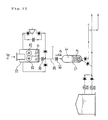
- the slurry mother liquid m in the slurry mother liquid storage tank 14 is supplied to a working fluid intake 141 of the jet pump 130 by a jet fluid driving pump 142, and further is supplied to the high-pressure ejection nozzle 140 by a high-pressure pump 143 for nozzle. Furthermore, to a pipe 144 connected to the discharge side of the jet pump 130, a slurry concentration controller 160 (hereinafter referred to as the "IPF controller") is mounted.
- the IPF controller 160 is structured by an IPF-measuring device 161 and a slurry concentration-adjusting tank 162.
- the IPF measuring device 161 arranges a pair of ring-shape electrodes 164a and 164b on an instrumentation pipe 163 being inserted in the pipe 144, via three insulation rings 165a, 165b, and 165c, keeping distance in the axial direction from each other.
- an electric conductivity-measuring device 166 is connected via a thin intake pipe 167. Only the slurry mother liquid as the conductive fluid enters into the electric conductivity-measuring device 166.
- the electric conductivity-measuring device 166 has a pair of electrodes (not shown) therein.
- An electric resistance-measuring device 168 measures the resistance between the pair of ring-shape electrodes 164a and 164b, or measures the electric resistance of a mixed-phase fluid (slurry containing pellets) passing through the instrumentation pipe 163,
- the electric conductivity-measuring device 166 measures the electric resistance (proportional to reciprocal number of electric conductivity ⁇ ) of the slurry mother liquid as a component of the mixed-phase fluid based on the resistance between the pair of electrodes positioned in the electric conductivity-measuring device 166.
- measured electric resistance r and electric conductivity ⁇ are inputted to a computing unit 169.
- the computing unit 169 stores the relation between the electric resistance r and the mixing rate ⁇ at each electric conductivity ⁇ of the slurry mother liquid.
- the mixing rate ⁇ corresponding to the inputted values is computed, and is outputted as the measured value.
- the slurry concentration-adjusting tank 162 is positioned at the downstream side of the IPF-measuring device 161, and is structured by a liquid-holding tank 170 and a penetration pipe 171 penetrating therethrough.
- the penetration pipe 171 is connected with the instrumentation pipe 163 of the IPF-measuring device, and has a small hole 172 at a portion of the penetration pipe 171 inside the liquid-holding tank 170, through which hole 172, gas and the slurry mother liquid flow out.
- a blower 174 is installed to be connected with a pipe 173 connected with the upper end of the liquid-holding tank 170, to return the non-reacted gas g' in the liquid-holding tank 170 to the storage tank 16.
- a slurry concentration-adjusting pump 176 is installed to be connected with a pipe 175 connected with the lower end of the liquid-holding tank 170, which thus returns the slurry mother liquid m in the liquid-holding tank 170 to the storage tank 16.
- the mixing rate ⁇ outputted from the IPF-measuring device 161 enters a controller 180 to control the slurry concentration-adjusting pump 176 attached to the slurry concentration-adjusting tank 162, thus to remove excess slurry mother liquid m.
- a slurry mother liquid charge pipe 145 and a slurry mother liquid discharge pipe 146 By controlling the slurry mother liquid discharge pump 136 (refer to Fig. 4 ) installed on the slurry mother liquid discharge pipe 146 by the distance-measuring device 135, the slurry mother liquid level m' in the storage tank 16 is controlled.
- the slurry mother liquid discharge pipe 146 has a valve 147.
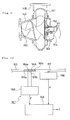
- the second slurry transfer pipe 19 has a slurry transfer pump 148 (refer to Fig. 4 ).
- the slurry transfer pump 148 has a structure to allow the suppression of the damage of pellets p. As shown in Fig.
- a spiral-shape impeller 150 in a suction cover 149 there is provided a spiral-shape impeller 150 in a suction cover 149.
- the reference number 151 signifies a casing
- 152 signifies an impeller flange
- 153 signifies a shaft sleeve
- 154 signifies a main shaft.
- the second valve B2, the third valve B3, the ninth valve B9, and the eleventh valve B11 are opened.
- the high pressure pump 41 is started to increase the pressure of the slurry mother liquid m in the slurry mother liquid storage tank 14 to a specified level (for example, 5.4 MPa or above), to charge the slurry mother liquid m under pressure into the slurry tank 13, and to return the non-reacted gas g' in the slurry tank 13 to the pressure vessel 23 of the granulation apparatus 9 via the gas-returning pipe 28.
- the second valve B2, the third valve B3, the ninth valve B9, and the eleventh valve B11 are closed.
- the eighth valve B8 is opened and closed instantaneously or in a short period of time (for example, opened and closed for 0.1 to 1.0 second), to release the internal pressure of the slurry tank 13 (for example, 5.4 MPa ⁇ 0.1 MPa).
- the low-pressure pump 42 increases the pressure of the slurry mother liquid m in the slurry mother liquid storage tank 14 to a specified level (for example, 0.4 MPa) to charge the slurry mother liquid m from the branch pipe 46 near the inlet of the slurry discharge pipe 33 at the bottom part of the slurry tank 13, and to adjust the concentration of the slurry s" which is pushed out from the slurry tank 13 to be about 30%.
- the tenth valve B10 and the eleventh valve B11 are opened.
- the second valve B2 the fourth to the sixth valves B4 to B6, the eighth valve B8, the tenth valve B10, and the eleventh valve B11 are closed.
- the second pellet carrying-out apparatus is different from the first pellet carrying-out apparatus in that a funnel 60 made of a perforated plate is provided in the pressure vessel 23 to prevent spread of pellets p, a pellet supply pipe 62 equipped with a valve 61 is mounted, a bypass pipe 63 is provided at the outer side of the gas-returning pipe 28 with the third valve B3, and the bypass pipe 63 has the pressure reducer 30, the twelfth valve B12, and the thirteenth valve B13.
- valve B3 of the gas-returning pipe 28 is closed.
- valve B8 of the slurry discharge pipe 33 connected to the bottom part of the slurry tank 13 is opened and closed for a short period of time to release the internal pressure of the slurry tank 13.
- valves B12 and B13 of the bypass pipe 63 are opened. Furthermore, the valve B2 of the pellet supply pipe 26 is opened to charge the depressurized (for example, 0.4 MPa) non-reacted gas g' from the pressure vessel 23 of the granulation apparatus 9 into the slurry tank 13 to push out the slurry s" in the slurry tank 13 into the first slurry transfer pipe 15.
- depressurized for example, 0.4 MPa
- the low-pressure pump 42 is started to increase the pressure of the slurry mother liquid m in the slurry mother liquid storage tank 14 to a specified level (for example, 0.4 MPa) to charge the slurry mother liquid m near the inlet of the slurry discharge pipe 33 at the bottom part of the slurry tank 13 via the branch pipe 46, and to adjust the concentration of the slurry s" which is pushed out from the slurry tank 13 to be about 30%.
- a specified level for example, 0.4 MPa
- each valve is closed. After that, by opening the second valve B2 and the second valve B3, the slurry tank 13 is again filled with high-pressure non-reacted gas g' (for example, about 5.4 MPa).
- the valves 133 at top of the storage tank are fully opened to fill the storage tank 16 with the slurry mother liquid m (refer to Fig. 18 ).
- the level of slurry mother liquid m is adjusted to the extent that pellets charged from the slurry-charging nozzles 131 are not damaged (for example, the level is kept apart from the top plate 17 of the storage tank by a distance of H).
- the slurry mother liquid m takes the route of: the slurry mother liquid storage tank 14 ⁇ the pressurizing pump 22 ⁇ the slurry mother liquid transfer pipe 15 ⁇ the storage tank 16 (refer to Fig. 1 ).
- valves 133 at top of the storage tank are once fully closed.
- the valves 133 are opened to charge the slurry s" into the storage tank 16, (refer to Fig. 18 ).
- the valves 133 are opened one by one, for example in sequential order from 133a, 133b, 133c, 133d, 133e, 133f, to 133g, (refer to Fig. 3 ), which equalizes the charge amount of slurry s" through each valve 133.
- each of slurry charge nozzles131 has a structure of freely rotating horizontally in 360°, as described before, the slurry charge nozzle 131 ejects the slurry s" horizontally at a specified initial velocity while rotating the nozzle by itself. Since the slurry s" immediately after the ejection requires a large falling distance, the slurry s" is distributed on the broad circumference of circle. With the progress of the charge of pellets, the slurry is gradually distributed on the narrow circumference of circle, and flattens the upper surface of the accumulated pellets.
- the slurry mother liquid discharge valve 147 of each of the storage tank bottoms 129a and 129b is fully opened and discharges successively the slurry mother liquid m while leaving behind the amount of shock-absorbing slurry mother liquid at the top of the accumulated pellets.
- the slurry mother liquid m takes the route of: the slurry mother liquid discharge pipe 146 ⁇ the slurry mother liquid discharge valve 147 ⁇ the slurry mother liquid discharge pump 136 ⁇ the slurry mother liquid storage tank 14.
- the level of the slurry mother liquid m is lowered to a level which gives equivalent height for both the pellet accumulation level n' and the slurry mother liquid m level, to store the pellets.
- the slurry mother liquid m is ejected from pluralities (for example, three)of the high-pressure ejection nozzles 140 attached to each of the tank bottom parts 129a and 129b to break up a lump of pellets p packed in the vicinity of the suction opening 134 of the jet pump 130.
- the slurry mother liquid m takes the route of: the slurry mother liquid storage tank 14 ⁇ the high pressure pump 143 for nozzle ⁇ the high pressure ejection nozzle 140.
- the slurry mother liquid m is ejected from the slurry charge nozzle 131 at the upper part of the storage tank in order to prepare the slurry volume concentration of 30%.
- the slurry mother liquid takes the route of: the slurry mother liquid storage tank 14 ⁇ the pressurizing pump 22 ⁇ the slurry charge nozzle 131.
- the slurry mother liquid m is ejected from the slurry mother liquid charge pipes 145 at each of the bottom parts 129a and 129b in order to prepare the slurry volume concentration of 30% (refer to Fig. 19 ).
- the slurry mother liquid m takes the route of: the slurry mother liquid storage tank 14 ⁇ the pressurizing pump 22 ⁇ the slurry mother liquid charge pipe 145.
- the jet pump 130 for discharging the pellets is started to suck the pellets p in the storage tank 16, and to charge the pellets into the pipe 144 under pressure.
- the slurry mother liquid m takes the route of: the slurry mother liquid storage tank 14 ⁇ the jet fluid-driving pump 142 ⁇ the jet pump 130.
- the IPF controller 160 is actuated to charge the slurry s" into the slurry concentration-adjusting tank 162, and to adjust the concentration of the slurry to be about 30%.
- the pellet slurry transfer pump 148 is started to transfer the slurry s" to the transport ship 17.
- the slurry s" takes the route of: the jet pump 130 ⁇ the slurry transfer pump 148 ⁇ the pellet loader ⁇ the hold 18 of the transport ship.
- the present invention can be applied in wide fields of production, storage, and transportation of gas hydrate other than natural gas hydrate.
Landscapes
- Chemical & Material Sciences (AREA)
- Oil, Petroleum & Natural Gas (AREA)
- Organic Chemistry (AREA)
- Geochemistry & Mineralogy (AREA)
- Geology (AREA)
- Life Sciences & Earth Sciences (AREA)
- General Life Sciences & Earth Sciences (AREA)
- Environmental & Geological Engineering (AREA)
- Engineering & Computer Science (AREA)
- Chemical Kinetics & Catalysis (AREA)
- General Chemical & Material Sciences (AREA)
- Filling Or Discharging Of Gas Storage Vessels (AREA)
- Glanulating (AREA)
- Organic Low-Molecular-Weight Compounds And Preparation Thereof (AREA)
Applications Claiming Priority (1)
| Application Number | Priority Date | Filing Date | Title |
|---|---|---|---|
| PCT/JP2007/052985 WO2008102427A1 (ja) | 2007-02-19 | 2007-02-19 | ガスハイドレートの製造、貯蔵及び輸送方法 |
Publications (2)
| Publication Number | Publication Date |
|---|---|
| EP2128228A1 true EP2128228A1 (de) | 2009-12-02 |
| EP2128228A4 EP2128228A4 (de) | 2010-10-13 |
Family
ID=39709712
Family Applications (1)
| Application Number | Title | Priority Date | Filing Date |
|---|---|---|---|
| EP07714511A Withdrawn EP2128228A4 (de) | 2007-02-19 | 2007-02-19 | Verfahren zur herstellung, zur aufbewahrung und zum transport für gashydrat |
Country Status (5)
| Country | Link |
|---|---|
| US (1) | US8231708B2 (de) |
| EP (1) | EP2128228A4 (de) |
| BR (1) | BRPI0720326A2 (de) |
| NO (1) | NO20093023L (de) |
| WO (1) | WO2008102427A1 (de) |
Cited By (1)
| Publication number | Priority date | Publication date | Assignee | Title |
|---|---|---|---|---|
| EP2130896A4 (de) * | 2007-03-30 | 2012-10-31 | Mitsui Shipbuilding Eng | Verfahren zur herstellung eines gemischten gashydrats |
Families Citing this family (4)
| Publication number | Priority date | Publication date | Assignee | Title |
|---|---|---|---|---|
| US9308507B2 (en) * | 2010-08-23 | 2016-04-12 | Dongguk University Industry-Academic Cooperation Foundation | Device for revaporizing natural gas |
| CN110345384B (zh) * | 2019-08-20 | 2024-03-26 | 西南石油大学 | 一种页岩气水合物浆液快速转运卸载装置及方法 |
| CN117307955B (zh) * | 2023-10-13 | 2025-11-18 | 中国科学院广州能源研究所 | 一种天然气水合物生产和输运系统 |
| CN119793158B (zh) * | 2024-12-18 | 2026-03-20 | 贵州盘江精煤股份有限公司 | 一种煤矿井下瓦斯循环抽排系统 |
Family Cites Families (10)
| Publication number | Priority date | Publication date | Assignee | Title |
|---|---|---|---|---|
| JP2001280592A (ja) | 2000-03-30 | 2001-10-10 | Mitsubishi Heavy Ind Ltd | 天然ガスの輸送方法 |
| JP2002220353A (ja) * | 2000-11-21 | 2002-08-09 | Mitsui Eng & Shipbuild Co Ltd | ガスハイドレートの造粒及び荷役並びに輸送方法 |
| JP3810310B2 (ja) * | 2001-12-04 | 2006-08-16 | 三井造船株式会社 | ガスハイドレートの荷役方法及び装置 |
| JP2004131272A (ja) * | 2002-10-15 | 2004-04-30 | National Maritime Research Institute | メタンガスハイドレートペレット荷揚げ装置 |
| JP4184906B2 (ja) * | 2003-09-16 | 2008-11-19 | 三井造船株式会社 | ガスハイドレートペレットおよびその製造方法 |
| JP4500567B2 (ja) * | 2004-03-16 | 2010-07-14 | 三井造船株式会社 | ガスハイドレート製造方法および製造装置 |
| JP4724379B2 (ja) * | 2004-05-20 | 2011-07-13 | 独立行政法人産業技術総合研究所 | ガスハイドレートの輸送及び貯蔵方法 |
| JP2006052261A (ja) * | 2004-08-10 | 2006-02-23 | Mitsui Eng & Shipbuild Co Ltd | ガスハイドレート製造プロセスにおける脱圧方法及び装置 |
| JP4444084B2 (ja) * | 2004-11-29 | 2010-03-31 | 株式会社川崎造船 | ガスハイドレートペレット移送装置と移送方法 |
| JP4758715B2 (ja) * | 2005-09-14 | 2011-08-31 | 三井造船株式会社 | ガスハイドレートペレットの移送方法 |
-
2007
- 2007-02-19 EP EP07714511A patent/EP2128228A4/de not_active Withdrawn
- 2007-02-19 WO PCT/JP2007/052985 patent/WO2008102427A1/ja not_active Ceased
- 2007-02-19 US US12/449,620 patent/US8231708B2/en not_active Expired - Fee Related
- 2007-02-19 BR BRPI0720326-8A patent/BRPI0720326A2/pt not_active IP Right Cessation
-
2009
- 2009-09-18 NO NO20093023A patent/NO20093023L/no not_active Application Discontinuation
Cited By (1)
| Publication number | Priority date | Publication date | Assignee | Title |
|---|---|---|---|---|
| EP2130896A4 (de) * | 2007-03-30 | 2012-10-31 | Mitsui Shipbuilding Eng | Verfahren zur herstellung eines gemischten gashydrats |
Also Published As
| Publication number | Publication date |
|---|---|
| WO2008102427A1 (ja) | 2008-08-28 |
| US20100083568A1 (en) | 2010-04-08 |
| NO20093023L (no) | 2009-09-18 |
| BRPI0720326A2 (pt) | 2013-01-15 |
| EP2128228A4 (de) | 2010-10-13 |
| US8231708B2 (en) | 2012-07-31 |
Similar Documents
| Publication | Publication Date | Title |
|---|---|---|
| EP2128228A1 (de) | Verfahren zur herstellung, zur aufbewahrung und zum transport für gashydrat | |
| US5733953A (en) | Low viscosity, high concentration drag reducing agent and method therefor | |
| EP1375630A1 (de) | Vorrichtung zur herstellung von gashydrat und gashydrat-dehydratisierungsvorrichtung | |
| JP2001342473A (ja) | ガスハイドレート製造装置およびガスハイドレート脱水装置 | |
| JPH0417309B2 (de) | ||
| JP2002220353A (ja) | ガスハイドレートの造粒及び荷役並びに輸送方法 | |
| CN86102096A (zh) | 煤浆系统 | |
| AU2008325692B9 (en) | Carbon dioxide underground storage system | |
| US20080072609A1 (en) | Process for producing slush fluid and apparatus therefor | |
| EP3122706B1 (de) | Verfahren und vorrichtung zur rückgewinnung von explosiven ladungen aus suspensionen mit diesen explosiven ladungen in trockenem zustand | |
| AU4485599A (en) | Method of treating carbon dioxide-containing gas and apparatus therefor | |
| KR101692260B1 (ko) | 가스 하이드레이트 펠릿 성형장치 | |
| JP4758715B2 (ja) | ガスハイドレートペレットの移送方法 | |
| CN101922426B (zh) | 用于高压液态货物的货物处理系统 | |
| JP5627567B2 (ja) | 少なくとも固形物及び液体を含む加圧流体を受けるためのセパレータ、並びに関連した装置及び方法 | |
| CN211770603U (zh) | 碎煤加压气化固液混合物处理系统 | |
| RU2713596C1 (ru) | Модульная мобильная технологическая линия получения эмульсионных промышленных взрывчатых веществ | |
| JP4817608B2 (ja) | ガスハイドレートの払い出し方法および払い出し装置 | |
| EP4467766B1 (de) | Anlage zum auflösen von wasserlöslichen polymeren in pulverform | |
| CN214192554U (zh) | 溶剂分装装置 | |
| JP2005008347A (ja) | 氷雪または気体水和物からなる粒状体のスラリー移送法 | |
| CN103980936B (zh) | 燃料在线脱水脱氧设备 | |
| CN115772422B (zh) | 一种超临界水气化反应器在线排渣装置及方法 | |
| CN119971905B (zh) | 氢化镁规模化生产装置及生产工艺 | |
| Zhu et al. | Research on green disposal technology and system of hydraulic cavitation based on retired ammunition |
Legal Events
| Date | Code | Title | Description |
|---|---|---|---|
| PUAI | Public reference made under article 153(3) epc to a published international application that has entered the european phase |
Free format text: ORIGINAL CODE: 0009012 |
|
| 17P | Request for examination filed |
Effective date: 20090722 |
|
| AK | Designated contracting states |
Kind code of ref document: A1 Designated state(s): AT BE BG CH CY CZ DE DK EE ES FI FR GB GR HU IE IS IT LI LT LU LV MC NL PL PT RO SE SI SK TR |
|
| DAX | Request for extension of the european patent (deleted) | ||
| A4 | Supplementary search report drawn up and despatched |
Effective date: 20100909 |
|
| STAA | Information on the status of an ep patent application or granted ep patent |
Free format text: STATUS: THE APPLICATION IS DEEMED TO BE WITHDRAWN |
|
| 18D | Application deemed to be withdrawn |
Effective date: 20110409 |