EP2128338A1 - Cylindre de réglage d'inclinaison - Google Patents
Cylindre de réglage d'inclinaison Download PDFInfo
- Publication number
- EP2128338A1 EP2128338A1 EP20090160766 EP09160766A EP2128338A1 EP 2128338 A1 EP2128338 A1 EP 2128338A1 EP 20090160766 EP20090160766 EP 20090160766 EP 09160766 A EP09160766 A EP 09160766A EP 2128338 A1 EP2128338 A1 EP 2128338A1
- Authority
- EP
- European Patent Office
- Prior art keywords
- yoke
- pin
- biegeeinstellwalze
- axis
- support means
- Prior art date
- Legal status (The legal status is an assumption and is not a legal conclusion. Google has not performed a legal analysis and makes no representation as to the accuracy of the status listed.)
- Withdrawn
Links
- 239000012530 fluid Substances 0.000 claims description 16
- 238000010276 construction Methods 0.000 claims description 14
- 238000005452 bending Methods 0.000 claims description 11
- 230000002706 hydrostatic effect Effects 0.000 claims description 9
- 239000000835 fiber Substances 0.000 abstract 1
- 238000004519 manufacturing process Methods 0.000 description 3
- 230000000712 assembly Effects 0.000 description 1
- 238000000429 assembly Methods 0.000 description 1
- 238000004364 calculation method Methods 0.000 description 1
- 238000001816 cooling Methods 0.000 description 1
- 238000005553 drilling Methods 0.000 description 1
- 230000009977 dual effect Effects 0.000 description 1
- 230000002349 favourable effect Effects 0.000 description 1
- 210000004907 gland Anatomy 0.000 description 1
- 239000000314 lubricant Substances 0.000 description 1
- 239000002184 metal Substances 0.000 description 1
- 238000005192 partition Methods 0.000 description 1
- 238000003825 pressing Methods 0.000 description 1
- 239000007787 solid Substances 0.000 description 1
- 239000011343 solid material Substances 0.000 description 1
- 230000006641 stabilisation Effects 0.000 description 1
- 238000011105 stabilization Methods 0.000 description 1
Images


Classifications
-
- D—TEXTILES; PAPER
- D21—PAPER-MAKING; PRODUCTION OF CELLULOSE
- D21G—CALENDERS; ACCESSORIES FOR PAPER-MAKING MACHINES
- D21G1/00—Calenders; Smoothing apparatus
- D21G1/02—Rolls; Their bearings
- D21G1/0206—Controlled deflection rolls
- D21G1/0213—Controlled deflection rolls with deflection compensation means acting between the roller shell and its supporting member
- D21G1/022—Controlled deflection rolls with deflection compensation means acting between the roller shell and its supporting member the means using fluid pressure
-
- D—TEXTILES; PAPER
- D21—PAPER-MAKING; PRODUCTION OF CELLULOSE
- D21G—CALENDERS; ACCESSORIES FOR PAPER-MAKING MACHINES
- D21G1/00—Calenders; Smoothing apparatus
- D21G1/02—Rolls; Their bearings
- D21G1/0206—Controlled deflection rolls
-
- F—MECHANICAL ENGINEERING; LIGHTING; HEATING; WEAPONS; BLASTING
- F16—ENGINEERING ELEMENTS AND UNITS; GENERAL MEASURES FOR PRODUCING AND MAINTAINING EFFECTIVE FUNCTIONING OF MACHINES OR INSTALLATIONS; THERMAL INSULATION IN GENERAL
- F16C—SHAFTS; FLEXIBLE SHAFTS; ELEMENTS OR CRANKSHAFT MECHANISMS; ROTARY BODIES OTHER THAN GEARING ELEMENTS; BEARINGS
- F16C13/00—Rolls, drums, discs, or the like; Bearings or mountings therefor
- F16C13/02—Bearings
- F16C13/022—Bearings supporting a hollow roll mantle rotating with respect to a yoke or axle
- F16C13/024—Bearings supporting a hollow roll mantle rotating with respect to a yoke or axle adjustable for positioning, e.g. radial movable bearings for controlling the deflection along the length of the roll mantle
- F16C13/026—Bearings supporting a hollow roll mantle rotating with respect to a yoke or axle adjustable for positioning, e.g. radial movable bearings for controlling the deflection along the length of the roll mantle by fluid pressure
Definitions
- the invention relates to a Biegeeinstellwalze for treating a paper, cardboard, tissue or other running fibrous web in a machine for producing and / or finishing the same, with a, about a fixed, supported in bearings axis rotatable roll shell, which at least one Support means is pressed on the axis to form a press nips for the fibrous web in the direction of a counter-pressure element.
- the axes of Biegeeinstellwalzen are usually made completely forged or cast, the axle bale is preferably carried out round. To meet the strength requirements, the axes have enormous dimensions and therefore a very high weight due to the high pressing forces in the press nip and the length of often more than 10 m. The high weight of the axle can easily exceed the capacity of available hoists for very wide machines.
- the object of the invention is therefore to provide a Biegeeinstellwalze whose axis overcomes the disadvantages of the prior art described.
- the object is achieved in that the axis of two substantially rotationally symmetrical pin with bearings and an intermediate and connected to the two pins yoke builds up.
- the roll ends are formed as in conventional bending set.
- these roller ends are formed in the region of the axis by two rotationally symmetrical, with respect to the total length of the axis relatively short pin.
- the spigots are cast and / or forged and have a precision that is the camp recording fair.
- Between the pins is a kind of intermediate piece, which may consist of one or more parts, built, which is called yoke in the following. Due to the multi-parting, it is much easier to produce the axle. Since the yoke connecting the pins can be produced in a variety of ways and adapted to the required strength requirements, it is also possible to make the overall axis as light as possible and vibration-resistant.
- the yoke is a welded construction.
- a composed of sheets and / or profiles yoke can be designed very reliable calculation methods in its strength and deflection properties and is clearly much easier than a usually used to date rotationally symmetric solid material.
- the space for supply lines of a pressurized fluid necessary for the support devices can be created by a welded construction. This can be applied to today's very elaborate axis-parallel holes are omitted inside the entire axis.
- the yoke has the shape of an elongated in the axial direction of the Biegeeinstellwalze and preferably hollow box. Such a box tolerates very high bending moments without significant deflection.
- the cross-sectional area of the yoke is not larger at its ends than the end face of the pin. Because of this, the yoke is connectable at its entire circumference with the pin. For example, a weld can be placed around the yoke end, which joins the yoke with each pin to form an axle.
- the shell inner circumference of the roller need only be dimensioned to the outer diameter of the pin.
- the roller can be supplied via at least one channel in at least one pin with a pressurized fluid.
- the pin is rotatably mounted during operation and thus forms the ideal location for the supply of the pressurized fluid that is needed for the support elements.
- the passage through the pin is to be performed quickly with holes, especially since not as in the prior art, the bore must be continued through the middle part of the axis.
- the at least one channel axially in the pin out and radially leads out of the pin.
- at least two holes are required per channel, which meet in the journal, namely an axially parallel inlet bore in the end face of the pin and a radial hole already lying below the jacket towards the inner ring space of the bending adjusting (between axle and roll jacket). But you have the opportunity to connect in a simple and accessible way further supply lines.
- At least one supply line is provided along the wall of the yoke from the channel to the support means.
- the supply lines which lead in the direction of the support elements, can be so easily attached to the wall of the yoke.
- a described welded construction in the form of a box favors this structure in that pipes can be screwed on both inside and outside on the sheets or profiles. And the box can by its construction have such a shape that there is enough space for the supply lines between the yoke and the rotating roll shell.
- the at least one supply line is attached to an outer wall of the yoke parallel to the roll axis and this covers at least over a third of their Jochines.
- Such long straight supply lines are particularly easy to attach and can ensure the inflow even up to the middle of the roll without problems.
- At least one support device on the yoke comprises at least one cylinder for a piston of a hydrostatic support element.
- Hydrostatic support elements for Biegeeinstellwalzen are well known and have been proven by their satisfactory mode of action.
- Also in the yoke wall of a box welded from sheet metal can be integrated by drilling such a cylinder, which in turn can accommodate a hydrostatic support element piston.
- a connecting line for the pressurized fluid from the supply line is accommodated in the cylinder in the interior of the yoke. There they are housed protected and take with their glands no space between the axis and roll shell.
- connection line is accommodated in or on a support arrangement of the welded construction.
- partition plates in the welded construction of the yoke are simultaneously used as a holder for the connection lines.
- At least one support device is provided in the journal.
- the first cylinder for a hydrostatic support element piston of a support element row extending over the entire length of the axis is then already accommodated in the journal in accordance with the invention.
- too strong stresses that could act on the connection spigot yoke, if only in the yoke support elements are present, can be avoided.
- a longer and simpler to produce weld seam is possible for fixing the pin on the yoke, as if the pin is inserted only in the yoke.
- the yoke is connected to at least one profile which serves as a drainage channel for pressurized fluid drawn from the roller.
- the introduced via the hydrostatic support elements in the roll interior pressure fluid is usually routed through the creator and connected to these drain lines out of the roller.
- an additional hollow profile for stiffening can be easily integrated, which can also serve as a drainage channel at the same time.
- a deflection roll 1 according to the invention is shown. It works with a counter-pressure element 11 together, which is only partially and shown in phantom.
- a fibrous web 2 is treated under pressure.
- Such rolls are typically used in calenders and presses.
- support means 6, 16 which are supported on the fixed axis 3 and act against a rotating roll shell 4 in order to influence this in its deflection can.
- bearings 5 At the ends of the axle is supported in bearings 5, which are housed for example in the stiffening of a calender or a press.
- this is a (in Fig. 1 stylized) Spherical bearing, because the axle does not rotate and the bearing only has to absorb the deflection of axle 3.
- axes of the roller according to the invention In contrast to conventional axes of the roller according to the invention of two rotationally symmetrical pin 7.1,7.2, which also show the bearing seat, and a yoke 8 mounted therebetween assembled.
- the axis is thus not made “from the solid", but has an intermediate piece, a yoke 8, which is formed in a favorable manufacturing form as a welded construction 9 and represents a hollow box with required moments of inertia.
- the entire axis 3 is much easier and much faster to produce.
- the axis need not be pierced lengthwise, which is very problematic in calenders and presses, which are becoming ever wider.
- Fig. 2 shows, in the roll according to the invention only one or both pins 7.1, 7.2 has to be drilled axially and this channel 14 then continues to extend radially and exit from the pin 7.1, 7.2 at its circumference.
- a support means 16 is already provided for the casing in the region of the pin 7.1, 7.2, so here is a supply channel in the production no problem.
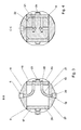
- FIG. 3 one recognizes the simple construction of the yoke. It basically consists of two lateral plates 26 and two welded to these lids 27, in which the receptacle for at least one support means 6 can be accommodated.
- the support device 6 is a hydrostatic support element which consists of at least one cylinder 19 in the cover 27 and a piston 20. Below the piston leads a connecting line 21, the pressurized fluid in the cylinder 19. It forms Thus, a pressure chamber in which a force acts on the piston 20, which in turn presses against the jacket 4.
- the mode of action of hydrostatic support devices in bending adjustment is known and need not be further explained here.
- connection lines 21 to the support means of the roller can be easily prefabricated and housed protected inside the yoke.
- three sides, ie a lateral plate 26 and at least one cover 27, are first connected to one another, for example, welded. With curved pipe sections, the connecting lines 21 are then formed. Subsequently, the welded construction 9 can be closed by the second cover 27 and the second lateral plate 26.
- a supply line 15 along the yoke leads a supply line 15 along the yoke to the connecting line 21.
- the formed as a side plate 26 wall 17, in particular the outer wall 18, is particularly well suited to several of these supply lines 15, all in each case a connecting line 21 for a support means 6 ends to fasten.
- sufficient clearance is provided between the wall of the side plate 26 and the inner circumference of the roll shell to accommodate a plurality of supply lines in the roll.
- FIG. 4 represents an alternative embodiment of the connecting lines.
- Each connecting line is in the form of two holes in a support assembly 22, for example, a bulkhead introduced.
- the support assemblies 22 now take on a dual function, namely the stabilization of the welded construction 9 and the possibility of supplying the support means 6 with pressurized fluid.
- the support assembly 22 within the yoke may be a standard part for different Biegeeinstellwalzen and already have holes to different possible positions for support means.
- the axle is composed of three parts, two pins 7.1, 7.2 and the yoke in between.
- Their direction of action against the jacket, not shown, points to the counter-pressure element (for example, a roller) and the fibrous web to be treated therebetween.
- the counter-pressure element for example, a roller
- Approximately at right angles to the direction of action run on the outer wall 18 of the yoke 8 parallel to the axis of the supply lines 15. They begin at the radial outlet of the channels 14 from the pins 7.1, 7.2 and ends at the level of the respective support means to be supplied, where they communicate with the respective connecting line get connected.
- FIG. 5 a mounted on the wall profile, in this case a U-profile 23, as in FIG. 3 and FIG. 4 better recognizes, shown. It is connected to at least one creator 25, the excess pressure fluid, so for example oil, scoops from the roller and thus provides a low required drive power of the roller.
- the excess pressure fluid so for example oil
- the profile forms quasi an outlet channel 24, in which the pressure fluid is brought to an outlet channel 28 from the roller. In addition, it serves to stiffen the welded construction of the yoke 8.
- Such profiles can also take on other functions, such as the supply of cooling oil or lubricants.
- the yoke 8 need not necessarily be composed of two plates 26 and two lids 27, but may be any box shape of a variety of sheets and profiles.
Landscapes
- Physics & Mathematics (AREA)
- Fluid Mechanics (AREA)
- Engineering & Computer Science (AREA)
- General Engineering & Computer Science (AREA)
- Mechanical Engineering (AREA)
- Paper (AREA)
Applications Claiming Priority (1)
| Application Number | Priority Date | Filing Date | Title |
|---|---|---|---|
| DE200810002112 DE102008002112A1 (de) | 2008-05-30 | 2008-05-30 | Biegeeinstellwalze |
Publications (1)
| Publication Number | Publication Date |
|---|---|
| EP2128338A1 true EP2128338A1 (fr) | 2009-12-02 |
Family
ID=41112557
Family Applications (1)
| Application Number | Title | Priority Date | Filing Date |
|---|---|---|---|
| EP20090160766 Withdrawn EP2128338A1 (fr) | 2008-05-30 | 2009-05-20 | Cylindre de réglage d'inclinaison |
Country Status (2)
| Country | Link |
|---|---|
| EP (1) | EP2128338A1 (fr) |
| DE (1) | DE102008002112A1 (fr) |
Cited By (1)
| Publication number | Priority date | Publication date | Assignee | Title |
|---|---|---|---|---|
| WO2014195151A1 (fr) * | 2013-06-06 | 2014-12-11 | Voith Patent Gmbh | Cylindre et production d'un axe de cylindre |
Citations (8)
| Publication number | Priority date | Publication date | Assignee | Title |
|---|---|---|---|---|
| CH383087A (de) | 1960-05-11 | 1964-10-15 | Benninger Ag Maschf | Biegungsarme Walze |
| DE2942002A1 (de) * | 1979-10-17 | 1981-05-07 | Kleinewefers Gmbh, 4150 Krefeld | Druckbehandlungswalze |
| EP0241442A2 (fr) * | 1986-04-09 | 1987-10-14 | Valmet Oy | Procédé pour contrôler la déflexion d'un rouleau de réglage de la flexion et rouleau pour machine à papier appliquant le procédé |
| DE29622141U1 (de) | 1996-12-20 | 1997-02-13 | Voith Sulzer Papiermaschinen GmbH, 89522 Heidenheim | Tambour zum Aufwickeln einer Materialbahn |
| WO1998042992A1 (fr) | 1997-03-20 | 1998-10-01 | Valmet Corporation | Rouleau |
| DE29902451U1 (de) | 1998-12-16 | 1999-05-27 | Valmet Corp., Helsinki | Vorrichtung zum Kalandrieren von Papier |
| WO2003046278A1 (fr) * | 2001-11-29 | 2003-06-05 | Voith Paper Patent Gmbh | Rouleau de presse |
| WO2004085156A1 (fr) | 2003-03-26 | 2004-10-07 | Koenig & Bauer Aktiengesellschaft | Cylindre comprenant un arbre et une enveloppe mobile autour de l'arbre |
-
2008
- 2008-05-30 DE DE200810002112 patent/DE102008002112A1/de not_active Withdrawn
-
2009
- 2009-05-20 EP EP20090160766 patent/EP2128338A1/fr not_active Withdrawn
Patent Citations (8)
| Publication number | Priority date | Publication date | Assignee | Title |
|---|---|---|---|---|
| CH383087A (de) | 1960-05-11 | 1964-10-15 | Benninger Ag Maschf | Biegungsarme Walze |
| DE2942002A1 (de) * | 1979-10-17 | 1981-05-07 | Kleinewefers Gmbh, 4150 Krefeld | Druckbehandlungswalze |
| EP0241442A2 (fr) * | 1986-04-09 | 1987-10-14 | Valmet Oy | Procédé pour contrôler la déflexion d'un rouleau de réglage de la flexion et rouleau pour machine à papier appliquant le procédé |
| DE29622141U1 (de) | 1996-12-20 | 1997-02-13 | Voith Sulzer Papiermaschinen GmbH, 89522 Heidenheim | Tambour zum Aufwickeln einer Materialbahn |
| WO1998042992A1 (fr) | 1997-03-20 | 1998-10-01 | Valmet Corporation | Rouleau |
| DE29902451U1 (de) | 1998-12-16 | 1999-05-27 | Valmet Corp., Helsinki | Vorrichtung zum Kalandrieren von Papier |
| WO2003046278A1 (fr) * | 2001-11-29 | 2003-06-05 | Voith Paper Patent Gmbh | Rouleau de presse |
| WO2004085156A1 (fr) | 2003-03-26 | 2004-10-07 | Koenig & Bauer Aktiengesellschaft | Cylindre comprenant un arbre et une enveloppe mobile autour de l'arbre |
Cited By (3)
| Publication number | Priority date | Publication date | Assignee | Title |
|---|---|---|---|---|
| WO2014195151A1 (fr) * | 2013-06-06 | 2014-12-11 | Voith Patent Gmbh | Cylindre et production d'un axe de cylindre |
| CN105264142A (zh) * | 2013-06-06 | 2016-01-20 | 福伊特专利有限公司 | 辊及辊轴的制造 |
| CN110714357A (zh) * | 2013-06-06 | 2020-01-21 | 福伊特专利有限公司 | 辊和用于制造轴的方法 |
Also Published As
| Publication number | Publication date |
|---|---|
| DE102008002112A1 (de) | 2009-12-03 |
Similar Documents
| Publication | Publication Date | Title |
|---|---|---|
| DE3832324C2 (fr) | ||
| EP0043119A1 (fr) | Cylindre presseur à réglage de la flexion | |
| WO1992017641A1 (fr) | Presse a rouleaux | |
| DE3025799C2 (de) | Preßwalze, deren Durchbiegung einstellbar ist | |
| EP0685660A1 (fr) | Rouleau pour machine à papier | |
| DE3329595C2 (de) | Walze für einen Folienziehkalander | |
| DE3889122T2 (de) | Selbst-belastende durchbiegungseinstellwalze. | |
| AT392661B (de) | Presswalze, deren durchbiegung einstellbar ist | |
| EP2128338A1 (fr) | Cylindre de réglage d'inclinaison | |
| EP1239170B1 (fr) | Rouleau à auto-réglage de la flexion | |
| DE3735491A1 (de) | Verfahren in einer durchbiegungsgeregelten walze und eine das verfahren anwendende walzenvorrichtung | |
| DE3024575C2 (de) | Preßwalze, deren Durchbiegung einstellbar ist | |
| AT510755B1 (de) | Verbindungsanordnung | |
| DE8817076U1 (de) | Kalander | |
| DE10393228B4 (de) | Pressvorrichtung | |
| EP1995378A2 (fr) | Rouleau aspirant à sabot | |
| DE102012205187A1 (de) | Presswalze für eine Maschine zur Herstellung einer Faserstoffbahn | |
| EP0745725A2 (fr) | Presse à rouleaux | |
| EP1956137A2 (fr) | Rouleau compresseur | |
| EP2151522A1 (fr) | Agencement de presse pour machine à papier | |
| DE102008026496A1 (de) | Walze mit selbsteinstellbarer Durchbiegung | |
| EP1956138B1 (fr) | Rouleau compresseur | |
| DE1461221A1 (de) | Walze fuer die Druckbehandlung von Warenbahnen | |
| DE102007033579B4 (de) | Durchbiegungsausgleichswalze einer Papier-/Kartonmaschine oder einer Ausrüstungsmaschine | |
| WO2013079537A1 (fr) | Empoise et son procédé de fabrication |
Legal Events
| Date | Code | Title | Description |
|---|---|---|---|
| PUAI | Public reference made under article 153(3) epc to a published international application that has entered the european phase |
Free format text: ORIGINAL CODE: 0009012 |
|
| AK | Designated contracting states |
Kind code of ref document: A1 Designated state(s): AT BE BG CH CY CZ DE DK EE ES FI FR GB GR HR HU IE IS IT LI LT LU LV MC MK MT NL NO PL PT RO SE SI SK TR |
|
| 17P | Request for examination filed |
Effective date: 20100602 |
|
| 17Q | First examination report despatched |
Effective date: 20110107 |
|
| RIC1 | Information provided on ipc code assigned before grant |
Ipc: F16C 13/02 20060101AFI20150318BHEP Ipc: D21G 1/02 20060101ALI20150318BHEP |
|
| STAA | Information on the status of an ep patent application or granted ep patent |
Free format text: STATUS: THE APPLICATION IS DEEMED TO BE WITHDRAWN |
|
| 18D | Application deemed to be withdrawn |
Effective date: 20150806 |