EP2128376B1 - Flussdrosselungskupplung - Google Patents
Flussdrosselungskupplung Download PDFInfo
- Publication number
- EP2128376B1 EP2128376B1 EP09170752A EP09170752A EP2128376B1 EP 2128376 B1 EP2128376 B1 EP 2128376B1 EP 09170752 A EP09170752 A EP 09170752A EP 09170752 A EP09170752 A EP 09170752A EP 2128376 B1 EP2128376 B1 EP 2128376B1
- Authority
- EP
- European Patent Office
- Prior art keywords
- hollow tubular
- tubular member
- aperture
- coupling
- flow restrictor
- Prior art date
- Legal status (The legal status is an assumption and is not a legal conclusion. Google has not performed a legal analysis and makes no representation as to the accuracy of the status listed.)
- Active
Links
Images
Classifications
-
- E—FIXED CONSTRUCTIONS
- E21—EARTH OR ROCK DRILLING; MINING
- E21B—EARTH OR ROCK DRILLING; OBTAINING OIL, GAS, WATER, SOLUBLE OR MELTABLE MATERIALS OR A SLURRY OF MINERALS FROM WELLS
- E21B17/00—Drilling rods or pipes; Flexible drill strings; Kellies; Drill collars; Sucker rods; Cables; Casings; Tubings
- E21B17/02—Couplings; joints
- E21B17/04—Couplings; joints between rod or the like and bit or between rod and rod or the like
- E21B17/042—Threaded
-
- E—FIXED CONSTRUCTIONS
- E21—EARTH OR ROCK DRILLING; MINING
- E21B—EARTH OR ROCK DRILLING; OBTAINING OIL, GAS, WATER, SOLUBLE OR MELTABLE MATERIALS OR A SLURRY OF MINERALS FROM WELLS
- E21B17/00—Drilling rods or pipes; Flexible drill strings; Kellies; Drill collars; Sucker rods; Cables; Casings; Tubings
- E21B17/10—Wear protectors; Centralising devices, e.g. stabilisers
- E21B17/1078—Stabilisers or centralisers for casing, tubing or drill pipes
-
- E—FIXED CONSTRUCTIONS
- E21—EARTH OR ROCK DRILLING; MINING
- E21B—EARTH OR ROCK DRILLING; OBTAINING OIL, GAS, WATER, SOLUBLE OR MELTABLE MATERIALS OR A SLURRY OF MINERALS FROM WELLS
- E21B21/00—Methods or apparatus for flushing boreholes, e.g. by use of exhaust air from motor
- E21B21/10—Valve arrangements in drilling-fluid circulation systems
- E21B21/103—Down-hole by-pass valve arrangements, i.e. between the inside of the drill string and the annulus
-
- E—FIXED CONSTRUCTIONS
- E21—EARTH OR ROCK DRILLING; MINING
- E21B—EARTH OR ROCK DRILLING; OBTAINING OIL, GAS, WATER, SOLUBLE OR MELTABLE MATERIALS OR A SLURRY OF MINERALS FROM WELLS
- E21B43/00—Methods or apparatus for obtaining oil, gas, water, soluble or meltable materials or a slurry of minerals from wells
- E21B43/12—Methods or apparatus for controlling the flow of the obtained fluid to or in wells
-
- Y—GENERAL TAGGING OF NEW TECHNOLOGICAL DEVELOPMENTS; GENERAL TAGGING OF CROSS-SECTIONAL TECHNOLOGIES SPANNING OVER SEVERAL SECTIONS OF THE IPC; TECHNICAL SUBJECTS COVERED BY FORMER USPC CROSS-REFERENCE ART COLLECTIONS [XRACs] AND DIGESTS
- Y10—TECHNICAL SUBJECTS COVERED BY FORMER USPC
- Y10T—TECHNICAL SUBJECTS COVERED BY FORMER US CLASSIFICATION
- Y10T29/00—Metal working
- Y10T29/49—Method of mechanical manufacture
- Y10T29/49826—Assembling or joining
Definitions
- the description relates to a flow restrictor coupling and particularly to a flow restrictor coupling for an oil well.
- Production tubing string is made up of individual tubing sections approximately 9.1 metres (30 feet) long. Attached to the top end of each tubing section is a coupling with two female thread forms to allow corresponding male threads on the end of the tubing sections to be threaded together to create one continuous tubing string.
- the rock which makes up the oil reservoir may vary in type and physical characteristics, but the main characteristic of interest is the permeability of the rock.
- the permeability determines the ease with which the oil can flow through the rock and into the oil well.
- Certain rocks such as sandstone have a relatively even permeability and are called homogeneous. Oil can flow through the homogeneous rock at a relatively even pace and will be produced evenly across the drilled section of reservoir.
- Other reservoir rocks such as limestone and chalk can be heavily, naturally fractured and vary greatly in permeability. These rocks are known as heterogeneous. Oil from a heterogeneous reservoir will produce mainly from the areas of highest permeability where the fractures occur.
- the oil well may be drilled through a considerable length of the oil reservoir, the high permeability zones may account for only 10-15% of the length of the drilled reservoir section. If allowed to produce directly into the drilled hole and production tubing string, the oil will never be produced from the remaining 85-90% of the drilled section thus reducing the efficiency of the oil well.
- a second problem is that directly beneath the oil reservoir there is typically a layer of naturally occurring water.
- the aim is to produce as much oil as possible and to limit the amount of natural water produced. Over time as the oil is depleted, it is replaced by the natural water seeping up from the rock below it. In a homogeneous reservoir the water may rise slowly and evenly, prolonging the time before water eventually breaks through into the well bore. In a heterogeneous reservoir the mixed permeability of the reservoir and the natural faulting may allow water to be produced almost immediately at the expense of oil production.
- Devices which invoke this effect come in a variety of forms and have the common feature of restricting flow by creating a pressure drop as the oil passes through them.
- the restriction can take the form of a series of orifices or a tortuous flow path.
- the devices are provided in the production tubing string and are spaced out at intervals across the reservoir section. As the oil produces it will pass out of the oil reservoir rock and fill the annular area between the bore hole drilled through the reservoir and the outside of the production tubing string. It will then flow towards the flow restriction devices and enter the production tubing string as described above.
- a production tubing string passing through a 1000 metre section of reservoir may only be provided with between 5 and 10 devices. This limits the efficiency of the process and may reduce the extent of oil producing zones and thus reduce the time until water breakthrough.
- CA 2,132,458 discloses that in the oil and gas industry, well bores are commonly drilled horizontally through the oil or gas bearing reservoir rock. It is common to equip (“complete") the producing section with a special pipe (called a liner) which facilitates maintenance or enhancement of productive capacity. Since the producing section is so long (100 m to 2000 m) for horizontal wells in comparison to vertical wells (1 m to 20 m), previous conventional liner completion designs, which were primarily designed for vertical wells, are often prohibitively expensive for horizontal wells. In response to this expense, many horizontal wells are left uncompleted (“open hole”) or are completed with a simplified liner design, which compromises well performance.
- CA 2,132,458 therefore discloses a low cost ported liner design which enables the following: retrievability, reuse, clean outs of produced sand, hydraulic jetting of multiple simultaneous "perforations”, abrasive jetting of multiple simultaneous “perforations”, limited entry stimulation or chemical soaks, underbalanced operations, low torque and drag installation.
- CA 2,132,458 essentially discloses a specialized hole located in the liner couplings. For selective placement of fluid along the wellbore, the diameter and frequency of the ports may be varied.
- the description relates to a device capable of creating the necessary flow restriction and resultant pressure drop that can be produced at a fraction of the price of current devices.
- This allows an oilfield operator to install larger quantities of the device more evenly distributed across the oil reservoir. The result of this will be a more efficient production from a greater proportion of the reservoir and an extension of the time until water break-through.
- a flow restrictor coupling comprising: a hollow tubular member having at a first end thereof first means for engagement with an end of a first pipe and, at a second end thereof, second means for engagement with an end of a second pipe, wherein said hollow tubular member is arranged to couple said first pipe to said second pipe and to provide for fluid communication therebetween, said flow restrictor coupling further being arranged to present at least one aperture in a wall of said hollow tubular member between said first and second ends, the aperture having selectively variable dimensions for control of fluid flow therethrough.
- An advantage of the present invention is that, as oil is produced, it must pass through the at least one aperture to gain access to the production tubing string to be produced at the surface.
- each coupling can be set up to create a specific pressure drop for a given flow rate. This choking effect creates a back pressure on higher quality sections of the reservoir allowing tighter sections to contribute, thereby evening out the inflow profile from the well. This evening out of the inflow profile will result in better coning control, therefore prolonging the lifetime of the well before water break-through.
- fluid flow through said aperture is fixed upon selection of the aperture dimensions.
- said at least one aperture is arranged to receive an insert member arranged to control the said fluid flow.
- said-at least one insert member is formed with an aperture to allow fluid flow therethrough and such that, when said insert member is located in said at least one corresponding aperture of said hollow tubular member, said aperture of said insert member provides fluid communication between an exterior of said hollow tubular member and an interior of said hollow tubular member.
- said at least one aperture of said hollow tubular member is provided with a thread for engagebly receiving said insert member which is similarly provided with an external thread.
- the rate of fluid flow between the exterior of said hollow tubular member and the interior of said hollow tubular member via said aperture of said insert member is variable dependent on the number of insert members present in said hollow tubular member.
- the rate of fluid flow between the exterior of said hollow tubular member and the interior of said hollow tubular member via said aperture of said insert member is further variable by replacing at least one of a plurality of insert members with a corresponding blank insert member arranged for engagement with said corresponding at least one aperture of said hollow tubular member and further arranged to prevent fluid flowing between the exterior of said hollow tubular member and the interior of said hollow tubular member via the corresponding at least one aperture of said hollow tubular member in which said blank insert member is located.
- the coupling further comprises centralising means arranged to space regions of said flow restrictor coupling from formations external to said flow restrictor coupling.
- said centralising means comprises an annular member provided with an internal thread for engagement with an external thread provided on the exterior of said hollow tubular member.
- said centralising means is formed as part of said hollow tubular member such that the wall of said hollow tubular member is thicker in the region of the centralising means than the portion of the hollow tubular member where said insert member is located.
- said centralising means is located either at one end, or both ends, of said hollow tubular member.
- said first and second means of engagement comprise female threads arranged to cooperate with corresponding male threads at ends of said first and second pipes respectively.
- said at least one aperture of said hollow tubular member extends through a wall of said hollow tubular member at a position corresponding to said mid region.
- said first and second means of engagement comprise male threads arranged to cooperate with corresponding female threads at ends of said first and second pipes respectively.
- an insert member for use as the insert member described above.
- a blank insert member for use as the blank insert member described above.
- a centralising means for use as the centralising means described above.
- a pipeline system comprising a plurality of pipe sections and a plurality of flow restrictor couplings as described above, wherein said each flow restrictor coupling serves to couple adjacent pipe sections to allow fluid communication between said adjacent pipe sections.
- a method of forming a flow restrictor coupling comprising the steps of: providing a hollow tubular member having at a first end thereof first means for engagement with an end of a first pipe and, at a second end thereof, second means for engagement with an end of a second pipe; forming at least one aperture in a wall of said hollow tubular member between said first and second ends.
- the method further comprises the step of: locating, in said at least one aperture, a flow-restricting insert member.
- the method further comprises the step of: forming said at least one aperture with a thread for engagebly receiving said corresponding at least one insert member which is similarly formed with a thread.
- said insert member presents a flow-restricting aperture.
- the method further comprises the step of providing said coupling with a centralising means arranged to space regions of said flow restrictor coupling from formations external to said flow restrictor coupling.
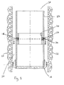
- Fig. 1 illustrates a flow restrictor coupling 10, which comprises four main components, namely: a coupling body 12; a nozzle 14; a blank nozzle 16; and a centraliser 18.
- the flow restrictor coupling 10 is illustrated in-situ, i.e. in an oil-well bore hole 20 drilled in an oil-bearing rock 22. Tubing sections of a production tubing string are not illustrated in Fig. 1 in order to aid clarity.
- Coupling body 12 comprises a hollow tubular member (preferably a thin-walled steel cylinder) having means at each end thereof for engaging with a tubing section so as to couple together adjacent tubing sections.
- the engaging means preferably comprise female thread forms machined in the interior wall of the hollow tubular member at each end thereof. These female threads are arranged to mate with corresponding male thread forms at the ends of tubing sections.
- the thread form on coupling body 12 matches the mating thread form on the production tubing sections, the production tubing sections can be coupled together to form a production tubing string.
- the female thread forms do not extend along the entire length of the interior wall of the coupling body 12, but rather extend only part way from the ends of the coupling body 12 along its length toward the centre.
- a section 24 of the interior wall of the coupling body remains unthreaded between the innermost ends of the female thread forms.
- At least one aperture is formed/provided in the wall of the coupling body 12 and extends between an exterior surface of the coupling body 12 to an interior surface of the coupling body 12 to allow fluid communication between the exterior and interior of the coupling body 12.
- the at least one aperture is formed/provided preferably at the mid-point along the length of the coupling body 12: a position which corresponds to section 24.
- a plurality of apertures are formed/provided in the wall of the coupling body 12 and are equally spaced around the perimeter of the coupling body 12.
- the apertures can themselves form the means by which fluid flows from the exterior of the coupling body 12 to a flow passage of the production tubing string in the interior of the coupling body 12.
- the apertures are each arranged to receive a corresponding nozzle 14 or blank nozzle 16.
- the nozzles 14/blank nozzles 16 may engage with the apertures formed in the coupling body 12 by any suitable means but preferably, the apertures are provided with a thread, with such a thread arranged to mate with a corresponding thread provided on the exterior of the nozzle 14 or blank nozzle 16. Thus, the nozzle 14 or blank nozzle 16 can be threaded directly into the apertures of the coupling body 12.
- Each nozzle 14 has an internal orifice 26 of given diameter to create a specific pressure drop for a specific flow rate of oil and water.
- the nozzles 14/blank nozzles 16 are preferably manufactured from a very hard, wear-resistant, material such as tungsten carbide.
- Blank nozzles 16 have substantially the same external dimensions as nozzles 14 so that they can be threaded into the apertures in coupling body 12. However, blank nozzles 16 differ from nozzles 14 in that they do not have an orifice and so do not allow fluid to pass between the exterior of the flow restrictor coupling 10 and the flow passage of the production tubing string in the interior of the flow restrictor coupling 10. Thus, the blank nozzles 16 can be used to replace nozzles 14 if the flow area through the combined nozzles 14/blank nozzles 16 is to be limited further.
- Centraliser 18 is located around the periphery of coupling body 12 and serves to hold the coupling body 12 and nozzles 14 away from the faces of the oil-well bore hole 20 in the oil reservoir.
- an oil-well bore hole is drilled horizontally or at a very shallow angle with the result that a production tubing string within the bore hole will lie against one side of the bore hole.
- the coupling body 12 might lie directly against the oil-well bore hole face and the entrance to the nozzle(s) would be partially or fully blocked, thereby affecting the desired pressure restriction characteristics of the present invention.
- centraliser 18 is a ring-shaped member provided with an internal thread (not shown) which is arranged to engage with a corresponding thread around the external periphery of the coupling body 12.
- the centraliser 18 need not be a discrete element, and may form part of the exterior of the coupling body 12.
- the centraliser 18 may comprise a section of said coupling body 12 which protrudes from the external surface of the coupling body 12. Such a section may be located at a centre, an end, or both ends of the coupling body, or at any point between the ends.
- the section need not be a continuous protrusion around the perimeter of the coupling body 12, but may comprise a number of protrusions separate from one another and located around the perimeter of the coupling body 12.
- Flow restrictor couplings 10 are provided in the production tubing string across an oil reservoir zone. Produced oil can only enter the production tubing string through the nozzles 14 mounted in the flow restrictor coupling 10.
- the nozzles 14 restrict the flow of oil into the production tubing string creating a pressure drop for any given flow rate which can be varied by altering the number of nozzles 14 and the diameter of the orifice in each nozzle 14.
- the pressure drop created allows oil to be produced from areas of the reservoir which would otherwise remain unproductive as the oil would take the path of least resistance and flow only from the most permeable regions.
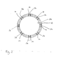
- FIG. 2 illustrates a cross-sectional top view of the flow restrictor coupling 10 of Fig. 1 taken along the line A-A.
- the coupling body 12 is provided with eight equally spaced apertures about its periphery, with seven of the apertures each containing therein a nozzle 14, and with the eighth aperture containing a blank nozzle 16.
- the apertures of the coupling body 12 for receiving the nozzles 14/blank nozzles 16 are located at positions around the periphery of the coupling body 12 such that pairs of said apertures are diametrically opposite.
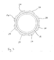
- Fig. 3 illustrates the ring-shaped member forming the centraliser 18.
- the centraliser 18 includes protrusions 28 equally spaced about a periphery of the centraliser 18. It is these protrusions 28 which space regions of the flow restrictor coupling 10 from rock (or other matter) surrounding the flow restrictor coupling 10 when the flow restrictor coupling 10 is located in a bore-hole.
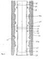
- FIG. 4 illustrates a cross-sectional side view of a production tubing string in-situ and comprising a plurality of flow restrictor couplings according to the present invention.
- two pipe sections 30a, 30b of a production tubing string located in a bore-hole 20 are coupled together by means of a flow restrictor coupling 10 according to the present invention.
- These pipe sections 30a, 3b are also provided with further flow restrictor couplings 10 at ends remote from the section where they are coupled together.
- These further flow restrictor couplings 10 are arranged to couple the pipe sections 30a, 30b to pipe sections (not shown) adjacent the remote ends in order to form the production tubing string.
Landscapes
- Engineering & Computer Science (AREA)
- Geology (AREA)
- Mining & Mineral Resources (AREA)
- Life Sciences & Earth Sciences (AREA)
- General Life Sciences & Earth Sciences (AREA)
- Fluid Mechanics (AREA)
- Environmental & Geological Engineering (AREA)
- Physics & Mathematics (AREA)
- Geochemistry & Mineralogy (AREA)
- Mechanical Engineering (AREA)
- Earth Drilling (AREA)
- Quick-Acting Or Multi-Walled Pipe Joints (AREA)
- Hydraulic Clutches, Magnetic Clutches, Fluid Clutches, And Fluid Joints (AREA)
- Lock And Its Accessories (AREA)
- Mechanical Operated Clutches (AREA)
- Water Treatment By Sorption (AREA)
Claims (17)
- Verfahren zur Herstellung einer Zuflussdrosselkupplung (10), das die folgenden Schritte aufweist:Bereitstellen eines hohlen, rohrförmigen Elementes (12), das an einem ersten Ende davon eine erste Einrichtung für einen Eingriff mit einem Ende eines ersten Rohres und an einem zweiten Ende davon eine zweite Einrichtung für einen Eingriff mit einem Ende eines zweiten Rohres aufweist;Ausbilden von mindestens einer Öffnung in einer Wand des hohlen, rohrförmigen Elementes (12) zwischen dem ersten und dem zweiten Ende, wobei die Abmessungen der mindestens einen Öffnung ausgewählt werden, um die Strömung in das hohle, rohrförmige Element zu steuern; undAuswählen der Anzahl der Öffnungen in der Flussdrosselkupplung und des Durchmessers der mindestens einen Öffnung, um einen spezifischen Druckabfall für eine bestimmte Strömungsgeschwindigkeit in das hohle, rohrförmige Element zu erzeugen.
- Verfahren nach Anspruch 1, das außerdem den Schritt des Anordnens eines Flussdrosseleinsatzelementes (14) in der mindestens einen Öffnung aufweist.
- Verfahren nach Anspruch 2, das außerdem den Schritt des Ausbildens der mindestens einen Öffnung mit einem Gewinde für ein ineinandergreifendes Aufnehmen des Einsatzelementes (14) aufweist, das gleichermaßen mit einem Gewinde ausgebildet ist.
- Verfahren nach Anspruch 2 oder 3, bei dem das Einsatzelement (14) eine Flussdrosselöffnung (26) verkörpert.
- Verfahren nach einem der Ansprüche 2 bis 4, bei dem die Geschwindigkeit der Strömung zwischen der Außenseite des hohlen, rohrförmigen Elementes (12) und der Innenseite des hohlen, rohrförmigen Elementes (12) über die Öffnung (26) des Einsatzelementes (14) in Abhängigkeit von der Anzahl der Einsatzelemente (14) veränderlich ist, die im hohlen, rohrförmigen Element (12) vorhanden sind.
- Verfahren nach Anspruch 5, bei dem die Geschwindigkeit der Strömung zwischen der Außenseite des hohlen, rohrförmigen Elementes (12) und der Innenseite des hohlen, rohrförmigen Elementes (12) über die Öffnung (26) des Einsatzelementes (14) außerdem veränderlich ist, indem mindestens eines von einer Vielzahl von Einsatzelementen (14) durch ein entsprechendes unbearbeitetes Einsatzelement (16) ersetzt wird, das für einen Eingriff mit der entsprechenden mindestens einen Öffnung des hohlen, rohrförmigen Elementes (12) angeordnet ist, und das außerdem angeordnet ist, um eine Strömung zwischen der Außenseite des hohlen, rohrförmigen Elementes (12) und der Innenseite des hohlen, rohrförmigen Elementes (12) über die entsprechende mindestens eine Öffnung des hohlen, rohrförmigen Elementes (12) zu verhindern, in der das unbearbeitete Einsatzelement (16) angeordnet ist.
- Verfahren nach einem der vorhergehenden Ansprüche, bei dem die erste und die zweite Einrichtung für einen Eingriff Innengewindegänge aufweisen, die so ausgebildet sind, dass sie mit entsprechenden Außengewindegängen an den Enden des jeweils ersten und zweiten Rohres zusammenwirken.
- Verfahren nach Anspruch 7, bei dem ein Abschnitt der Innenfläche in einem Mittelbereich (24) des hohlen, rohrförmigen Elementes (12) und abgelegen von den innersten Enden der Innengewindegänge gewindelos ist.
- Verfahren nach Anspruch 7 oder 8, bei dem sich die mindestens eine Öffnung des hohlen, rohrförmigen Elementes (12) durch eine Wand des hohlen, rohrförmigen Elementes (12) in einer Position entsprechend dem Mittelbereich (24) erstreckt.
- Verfahren nach einem der vorhergehenden Ansprüche, bei dem die erste und die zweite Einrichtung für einen Eingriff Außengewindegänge aufweisen, die so ausgebildet sind, dass sie mit entsprechenden Innengewindegängen an den Enden des jeweils ersten und zweiten Rohres zusammenwirken.
- Verfahren nach einem der vorhergehenden Ansprüche, das außerdem den Schritt des Versehens der Kupplung (10) mit einer Zentriereinrichtung (18) aufweist, die angeordnet ist, um Bereiche der Flussdrosselkupplung (10) von Formationen (22) außerhalb der Flussdrosselkupplung (10) in Abstand zu bringen.
- Verfahren nach Anspruch 11, bei dem die Zentriereinrichtung (18) ein ringförmiges Element aufweist, das mit einem Innengewinde für einen Eingriff mit einem Außengewinde versehen ist, das auf der Außenseite des hohlen, rohrförmigen Elementes (12) vorhanden ist.
- Verfahren nach Anspruch 11 oder 12, bei dem die Zentriereinrichtung (18) als Teil des hohlen, rohrförmigen Elementes (12) ausgebildet ist, so dass die Wand des hohlen, rohrförmigen Elementes (12) im Bereich der Zentriereinrichtung (18) dicker ist als der Abschnitt des hohlen, rohrförmigen Elementes (12), wo das Einsatzelement (14) angeordnet ist.
- Verfahren nach Anspruch 13, bei dem die Zentriereinrichtung (18) entweder an einem Ende oder an beiden Enden des hohlen, rohrförmigen Elementes (12) angeordnet ist.
- Verfahren zur Herstellung eines Rohrleitungssystems, das die folgenden Schritte aufweist:Bereitstellen einer Vielzahl von Rohrabschnitten und einer Vielzahl von Flussdrosselkupplungen (10), die nach einem der vorhergehenden Ansprüche hergestellt wurden; undVerwenden der Flussdrosselkupplungen (10), um benachbarte Rohrabschnitte zu kuppeln, um eine Fluidverbindung zwischen den benachbarten Rohrabschnitten zu gestatten.
- Verfahren zum Ausgleichen des Zuflussprofils eines Bohrloches, das eine Erdöllagerstättenzone schneidet, die Abschnitte mit höherer Durchlässigkeit und Abschnitte mit niedrigerer Durchlässigkeit aufweist, wobei das Verfahren die folgenden Schritte aufweist:Herstellen eines Steigrohrstranges durch Kuppeln von Rohren bei Verwendung von Kupplungen, die nach einem der Ansprüche 1 bis 14 hergestellt wurden; undZusammensetzen einer jeden Kupplung, um einen spezifischen Druckabfall für eine bestimmte Strömungsgeschwindigkeit zu erzeugen, und um daher eine Drosselwirkung und einen Gegendruck bei Abschnitten der Lagerstätte mit höherer Durchlässigkeit zu erzeugen, wodurch gestattet wird, dass die Abschnitte mit niedrigerer Durchlässigkeit fördern.
- Verfahren zum Bewirken einer Coning Control bei einem Bohrloch, das eine Erdöllagerstättenzone schneidet, wobei das Verfahren die folgenden Schritte aufweist:Herstellen eines Steigrohrstranges durch Kuppeln von Rohren bei Verwendung von Kupplungen, die nach einem der Ansprüche 1 bis 14 hergestellt wurden; undZusammensetzen einer jeden Kupplung, um einen spezifischen Druckabfall für eine bestimmte Strömungsgeschwindigkeit zu erzeugen, und um daher eine Drosselwirkung und einen Gegendruck zu erzeugen.
Applications Claiming Priority (2)
| Application Number | Priority Date | Filing Date | Title |
|---|---|---|---|
| GBGB0615042.9A GB0615042D0 (en) | 2006-07-29 | 2006-07-29 | Flow restrictor coupling |
| EP07110598A EP1882808B1 (de) | 2006-07-29 | 2007-06-19 | Flussdrosselungskupplung |
Related Parent Applications (2)
| Application Number | Title | Priority Date | Filing Date |
|---|---|---|---|
| EP07110598.5 Division | 2007-06-19 | ||
| EP07110598A Division EP1882808B1 (de) | 2006-07-29 | 2007-06-19 | Flussdrosselungskupplung |
Publications (3)
| Publication Number | Publication Date |
|---|---|
| EP2128376A2 EP2128376A2 (de) | 2009-12-02 |
| EP2128376A3 EP2128376A3 (de) | 2009-12-09 |
| EP2128376B1 true EP2128376B1 (de) | 2011-11-16 |
Family
ID=40278836
Family Applications (2)
| Application Number | Title | Priority Date | Filing Date |
|---|---|---|---|
| EP07110598A Active EP1882808B1 (de) | 2006-07-29 | 2007-06-19 | Flussdrosselungskupplung |
| EP09170752A Active EP2128376B1 (de) | 2006-07-29 | 2007-06-19 | Flussdrosselungskupplung |
Family Applications Before (1)
| Application Number | Title | Priority Date | Filing Date |
|---|---|---|---|
| EP07110598A Active EP1882808B1 (de) | 2006-07-29 | 2007-06-19 | Flussdrosselungskupplung |
Country Status (8)
| Country | Link |
|---|---|
| US (1) | US20100276927A1 (de) |
| EP (2) | EP1882808B1 (de) |
| AT (2) | ATE533916T1 (de) |
| CA (1) | CA2692233A1 (de) |
| DE (1) | DE602007002527D1 (de) |
| ES (1) | ES2377443T3 (de) |
| GB (1) | GB0615042D0 (de) |
| WO (1) | WO2008155578A1 (de) |
Families Citing this family (8)
| Publication number | Priority date | Publication date | Assignee | Title |
|---|---|---|---|---|
| GB0805216D0 (en) * | 2008-03-20 | 2008-04-30 | Flotech Ltd | Flow restrictor |
| CA2903316A1 (en) * | 2013-04-05 | 2014-10-09 | Halliburton Energy Services, Inc. | Controlling flow in a wellbore |
| NO339673B1 (no) * | 2014-06-03 | 2017-01-23 | Trican Completion Solutions Ltd | Strømningsstyrt nedihullsverktøy |
| CN105134101B (zh) * | 2015-08-21 | 2017-05-24 | 西南石油大学 | 一种深水钻井隔水管与钻杆防磨减磨保护装置 |
| US10494902B1 (en) * | 2018-10-09 | 2019-12-03 | Turbo Drill Industries, Inc. | Downhole tool with externally adjustable internal flow area |
| CN112031670B (zh) * | 2020-08-21 | 2022-01-28 | 中煤科工集团西安研究院有限公司 | 一种具有防掉钻功能的矿用钻杆 |
| CN112227975B (zh) * | 2020-09-29 | 2022-03-15 | 中煤科工集团西安研究院有限公司 | 一种仿动物筋-骨结构的双连接钻杆 |
| CN113700441B (zh) * | 2021-11-01 | 2021-12-31 | 中煤科工集团西安研究院有限公司 | 一种具有断裂自锁功能的矿用钻杆公接头及钻杆 |
Family Cites Families (38)
| Publication number | Priority date | Publication date | Assignee | Title |
|---|---|---|---|---|
| US365068A (en) * | 1887-06-21 | Coupling for joining pipes | ||
| US958100A (en) * | 1909-09-24 | 1910-05-17 | Harry R Decker | Strainer for oil and water wells. |
| US1379815A (en) * | 1920-07-30 | 1921-05-31 | Hall James Robert | Oil-well screen and liner cleaner |
| US2126575A (en) * | 1934-07-23 | 1938-08-09 | Ranney Leo | Method of and apparatus for recovering water from and supplying water to subterranean formations |
| US2178845A (en) * | 1936-10-10 | 1939-11-07 | Baker Oil Tools Inc | Safety circulation medium for well casings |
| US2170004A (en) * | 1937-09-07 | 1939-08-22 | Roger C Boughton | Pipe joint |
| US2167191A (en) * | 1938-02-25 | 1939-07-25 | Texas Co | Method and apparatus for screening wells |
| US2205119A (en) * | 1939-04-17 | 1940-06-18 | Security Engineering Co Inc | Method of setting drillable liners in wells |
| US2312579A (en) * | 1939-09-15 | 1943-03-02 | Pierce John B Foundation | Method of applying coupling devices |
| US2537066A (en) * | 1944-07-24 | 1951-01-09 | James O Lewis | Apparatus for controlling fluid producing formations |
| US2826254A (en) * | 1955-04-07 | 1958-03-11 | Johnston Testers Inc | Packing for mandrel of testing tool |
| US3310113A (en) * | 1964-06-12 | 1967-03-21 | Mabre P Maness | Well cleaner |
| US3360047A (en) * | 1965-05-18 | 1967-12-26 | Bob J Burnett | Well drilling device |
| US3747964A (en) * | 1971-12-15 | 1973-07-24 | N Nilsen | Quick coupling and seal |
| US4123800A (en) * | 1977-05-18 | 1978-10-31 | Mazzei Angelo L | Mixer-injector |
| US4258801A (en) * | 1979-06-14 | 1981-03-31 | Eastman Whipstock, Inc. | Dump valve for use with downhole motor |
| US4361193A (en) * | 1980-11-28 | 1982-11-30 | Mobil Oil Corporation | Method and arrangement for improving cuttings removal and reducing differential pressure sticking of drill strings in wellbores |
| US4782896A (en) * | 1987-05-28 | 1988-11-08 | Atlantic Richfield Company | Retrievable fluid flow control nozzle system for wells |
| US5526881A (en) * | 1994-06-30 | 1996-06-18 | Quality Tubing, Inc. | Preperforated coiled tubing |
| CA2132458A1 (en) * | 1994-08-31 | 1996-03-01 | Barry Richard Hassen | Multi- port oilfield liner connector |
| US5678592A (en) * | 1996-01-16 | 1997-10-21 | S. C. Johnson & Son, Inc. | Back flow prevention device |
| US5673725A (en) * | 1996-06-10 | 1997-10-07 | Knight Equipment International, Inc. | Air gap device with interchangeable parts |
| US5895076A (en) * | 1996-11-04 | 1999-04-20 | Tyler J. Elliot | Hose coupling shroud |
| US5842516A (en) * | 1997-04-04 | 1998-12-01 | Mobil Oil Corporation | Erosion-resistant inserts for fluid outlets in a well tool and method for installing same |
| US5881809A (en) * | 1997-09-05 | 1999-03-16 | United States Filter Corporation | Well casing assembly with erosion protection for inner screen |
| US5893641A (en) * | 1998-05-26 | 1999-04-13 | Garcia; Paul | Differential injector |
| EG22932A (en) * | 2000-05-31 | 2002-01-13 | Shell Int Research | Method and system for reducing longitudinal fluid flow around a permeable well tubular |
| FR2815073B1 (fr) * | 2000-10-09 | 2002-12-06 | Johnson Filtration Systems | Elements de drain ayant une crepine consitituee de tiges creuses pour collecter notamment des hydrocarbures |
| US6464013B2 (en) * | 2001-02-23 | 2002-10-15 | Kenneth A. Bystedt | Oil well casing centralizer coupling |
| NO314701B3 (no) * | 2001-03-20 | 2007-10-08 | Reslink As | Stromningsstyreanordning for struping av innstrommende fluider i en bronn |
| US6899176B2 (en) * | 2002-01-25 | 2005-05-31 | Halliburton Energy Services, Inc. | Sand control screen assembly and treatment method using the same |
| US7258166B2 (en) * | 2003-12-10 | 2007-08-21 | Absolute Energy Ltd. | Wellbore screen |
| US20060070675A1 (en) * | 2004-10-06 | 2006-04-06 | Maxwell Hsu | Pressurized gas-water mixer |
| US20070284037A1 (en) * | 2006-06-07 | 2007-12-13 | Jean Buytaert | Epoxy secured stop collar for centralizer |
| US20080041588A1 (en) * | 2006-08-21 | 2008-02-21 | Richards William M | Inflow Control Device with Fluid Loss and Gas Production Controls |
| US7731246B2 (en) * | 2006-09-29 | 2010-06-08 | Varco I/P, Inc. | Pipe coupling system |
| US7527305B2 (en) * | 2007-05-31 | 2009-05-05 | Hyslop William J | Hose connector with adjustable ambient air inlets |
| US7954555B2 (en) * | 2009-04-23 | 2011-06-07 | Baker Hughes Incorporated | Full function downhole valve and method of operating the valve |
-
2006
- 2006-07-29 GB GBGB0615042.9A patent/GB0615042D0/en not_active Ceased
-
2007
- 2007-06-19 AT AT09170752T patent/ATE533916T1/de active
- 2007-06-19 EP EP07110598A patent/EP1882808B1/de active Active
- 2007-06-19 DE DE602007002527T patent/DE602007002527D1/de not_active Expired - Fee Related
- 2007-06-19 AT AT07110598T patent/ATE443802T1/de not_active IP Right Cessation
- 2007-06-19 ES ES09170752T patent/ES2377443T3/es active Active
- 2007-06-19 EP EP09170752A patent/EP2128376B1/de active Active
-
2008
- 2008-06-18 US US12/665,524 patent/US20100276927A1/en not_active Abandoned
- 2008-06-18 CA CA002692233A patent/CA2692233A1/en not_active Abandoned
- 2008-06-18 WO PCT/GB2008/050464 patent/WO2008155578A1/en not_active Ceased
Also Published As
| Publication number | Publication date |
|---|---|
| DE602007002527D1 (de) | 2009-11-05 |
| GB0615042D0 (en) | 2006-09-06 |
| CA2692233A1 (en) | 2008-12-24 |
| ATE443802T1 (de) | 2009-10-15 |
| EP1882808B1 (de) | 2009-09-23 |
| US20100276927A1 (en) | 2010-11-04 |
| EP2128376A3 (de) | 2009-12-09 |
| ATE533916T1 (de) | 2011-12-15 |
| EP2128376A2 (de) | 2009-12-02 |
| WO2008155578A1 (en) | 2008-12-24 |
| EP1882808A1 (de) | 2008-01-30 |
| ES2377443T3 (es) | 2012-03-27 |
Similar Documents
| Publication | Publication Date | Title |
|---|---|---|
| EP1546506B1 (de) | Strömungssteuervorrichtung für einspritzrohrstrang | |
| EP1882808B1 (de) | Flussdrosselungskupplung | |
| US4782896A (en) | Retrievable fluid flow control nozzle system for wells | |
| US6457525B1 (en) | Method and apparatus for completing multiple production zones from a single wellbore | |
| US8893809B2 (en) | Flow control device with one or more retrievable elements and related methods | |
| US8418768B2 (en) | Bypass gaslift system, apparatus, and method for producing a multiple zones well | |
| US20060060352A1 (en) | Sand control completion having smart well capability and method for use of same | |
| US20170284179A1 (en) | Method for developing an oil bearing formation | |
| US9828838B2 (en) | Adjustable flow control assemblies, systems, and methods | |
| US9617836B2 (en) | Passive in-flow control devices and methods for using same | |
| EP2452042B1 (de) | Flussdrosselungsvorrichtung | |
| US20120061093A1 (en) | Multiple in-flow control devices and methods for using same | |
| AU2009227746A1 (en) | Flow restrictor | |
| WO2013124643A2 (en) | Downhole flow control device | |
| EP1502002B1 (de) | Bohrlochvorbereitung mit vereinigtem zufluss von bohrlochflüssigkeiten | |
| US20120145382A1 (en) | System and Method for Operating Multiple Valves | |
| CA2132458A1 (en) | Multi- port oilfield liner connector | |
| US12188337B2 (en) | Gas dispersal tool and associated methods and systems | |
| US20090250222A1 (en) | Reverse flow in-flow control device | |
| EP2463477B1 (de) | System und Verfahren zur Bedienung mehrerer Ventile | |
| EP1430200B1 (de) | Bohrlochsystem zum gleichzeitigen bohren und fördern | |
| Carpenter | Study Summarizes 20 Years of Horizontal Multistage Completions |
Legal Events
| Date | Code | Title | Description |
|---|---|---|---|
| PUAI | Public reference made under article 153(3) epc to a published international application that has entered the european phase |
Free format text: ORIGINAL CODE: 0009012 |
|
| PUAL | Search report despatched |
Free format text: ORIGINAL CODE: 0009013 |
|
| AC | Divisional application: reference to earlier application |
Ref document number: 1882808 Country of ref document: EP Kind code of ref document: P |
|
| AK | Designated contracting states |
Kind code of ref document: A2 Designated state(s): AT BE BG CH CY CZ DE DK EE ES FI FR GB GR HU IE IS IT LI LT LU LV MC MT NL PL PT RO SE SI SK TR |
|
| AK | Designated contracting states |
Kind code of ref document: A3 Designated state(s): AT BE BG CH CY CZ DE DK EE ES FI FR GB GR HU IE IS IT LI LT LU LV MC MT NL PL PT RO SE SI SK TR |
|
| 17P | Request for examination filed |
Effective date: 20100315 |
|
| 17Q | First examination report despatched |
Effective date: 20100414 |
|
| RIC1 | Information provided on ipc code assigned before grant |
Ipc: E21B 21/10 20060101ALI20110225BHEP Ipc: E21B 43/12 20060101ALI20110225BHEP Ipc: E21B 17/042 20060101AFI20110225BHEP Ipc: E21B 17/10 20060101ALI20110225BHEP |
|
| GRAP | Despatch of communication of intention to grant a patent |
Free format text: ORIGINAL CODE: EPIDOSNIGR1 |
|
| GRAS | Grant fee paid |
Free format text: ORIGINAL CODE: EPIDOSNIGR3 |
|
| GRAA | (expected) grant |
Free format text: ORIGINAL CODE: 0009210 |
|
| AC | Divisional application: reference to earlier application |
Ref document number: 1882808 Country of ref document: EP Kind code of ref document: P |
|
| AK | Designated contracting states |
Kind code of ref document: B1 Designated state(s): AT BE BG CH CY CZ DE DK EE ES FI FR GB GR HU IE IS IT LI LT LU LV MC MT NL PL PT RO SE SI SK TR |
|
| REG | Reference to a national code |
Ref country code: GB Ref legal event code: FG4D |
|
| REG | Reference to a national code |
Ref country code: CH Ref legal event code: EP |
|
| REG | Reference to a national code |
Ref country code: IE Ref legal event code: FG4D |
|
| REG | Reference to a national code |
Ref country code: DE Ref legal event code: R096 Ref document number: 602007018842 Country of ref document: DE Effective date: 20120202 |
|
| REG | Reference to a national code |
Ref country code: NL Ref legal event code: T3 |
|
| REG | Reference to a national code |
Ref country code: SE Ref legal event code: TRGR |
|
| REG | Reference to a national code |
Ref country code: ES Ref legal event code: FG2A Ref document number: 2377443 Country of ref document: ES Kind code of ref document: T3 Effective date: 20120327 |
|
| LTIE | Lt: invalidation of european patent or patent extension |
Effective date: 20111116 |
|
| PG25 | Lapsed in a contracting state [announced via postgrant information from national office to epo] |
Ref country code: IS Free format text: LAPSE BECAUSE OF FAILURE TO SUBMIT A TRANSLATION OF THE DESCRIPTION OR TO PAY THE FEE WITHIN THE PRESCRIBED TIME-LIMIT Effective date: 20120316 Ref country code: LT Free format text: LAPSE BECAUSE OF FAILURE TO SUBMIT A TRANSLATION OF THE DESCRIPTION OR TO PAY THE FEE WITHIN THE PRESCRIBED TIME-LIMIT Effective date: 20111116 |
|
| PG25 | Lapsed in a contracting state [announced via postgrant information from national office to epo] |
Ref country code: BE Free format text: LAPSE BECAUSE OF FAILURE TO SUBMIT A TRANSLATION OF THE DESCRIPTION OR TO PAY THE FEE WITHIN THE PRESCRIBED TIME-LIMIT Effective date: 20111116 Ref country code: GR Free format text: LAPSE BECAUSE OF FAILURE TO SUBMIT A TRANSLATION OF THE DESCRIPTION OR TO PAY THE FEE WITHIN THE PRESCRIBED TIME-LIMIT Effective date: 20120217 Ref country code: LV Free format text: LAPSE BECAUSE OF FAILURE TO SUBMIT A TRANSLATION OF THE DESCRIPTION OR TO PAY THE FEE WITHIN THE PRESCRIBED TIME-LIMIT Effective date: 20111116 Ref country code: SI Free format text: LAPSE BECAUSE OF FAILURE TO SUBMIT A TRANSLATION OF THE DESCRIPTION OR TO PAY THE FEE WITHIN THE PRESCRIBED TIME-LIMIT Effective date: 20111116 Ref country code: PT Free format text: LAPSE BECAUSE OF FAILURE TO SUBMIT A TRANSLATION OF THE DESCRIPTION OR TO PAY THE FEE WITHIN THE PRESCRIBED TIME-LIMIT Effective date: 20120316 Ref country code: PL Free format text: LAPSE BECAUSE OF FAILURE TO SUBMIT A TRANSLATION OF THE DESCRIPTION OR TO PAY THE FEE WITHIN THE PRESCRIBED TIME-LIMIT Effective date: 20111116 |
|
| PG25 | Lapsed in a contracting state [announced via postgrant information from national office to epo] |
Ref country code: CY Free format text: LAPSE BECAUSE OF FAILURE TO SUBMIT A TRANSLATION OF THE DESCRIPTION OR TO PAY THE FEE WITHIN THE PRESCRIBED TIME-LIMIT Effective date: 20111116 |
|
| PG25 | Lapsed in a contracting state [announced via postgrant information from national office to epo] |
Ref country code: BG Free format text: LAPSE BECAUSE OF FAILURE TO SUBMIT A TRANSLATION OF THE DESCRIPTION OR TO PAY THE FEE WITHIN THE PRESCRIBED TIME-LIMIT Effective date: 20120216 Ref country code: EE Free format text: LAPSE BECAUSE OF FAILURE TO SUBMIT A TRANSLATION OF THE DESCRIPTION OR TO PAY THE FEE WITHIN THE PRESCRIBED TIME-LIMIT Effective date: 20111116 Ref country code: CZ Free format text: LAPSE BECAUSE OF FAILURE TO SUBMIT A TRANSLATION OF THE DESCRIPTION OR TO PAY THE FEE WITHIN THE PRESCRIBED TIME-LIMIT Effective date: 20111116 Ref country code: DK Free format text: LAPSE BECAUSE OF FAILURE TO SUBMIT A TRANSLATION OF THE DESCRIPTION OR TO PAY THE FEE WITHIN THE PRESCRIBED TIME-LIMIT Effective date: 20111116 Ref country code: SK Free format text: LAPSE BECAUSE OF FAILURE TO SUBMIT A TRANSLATION OF THE DESCRIPTION OR TO PAY THE FEE WITHIN THE PRESCRIBED TIME-LIMIT Effective date: 20111116 |
|
| PGFP | Annual fee paid to national office [announced via postgrant information from national office to epo] |
Ref country code: DE Payment date: 20120613 Year of fee payment: 6 Ref country code: NL Payment date: 20120614 Year of fee payment: 6 |
|
| PG25 | Lapsed in a contracting state [announced via postgrant information from national office to epo] |
Ref country code: RO Free format text: LAPSE BECAUSE OF FAILURE TO SUBMIT A TRANSLATION OF THE DESCRIPTION OR TO PAY THE FEE WITHIN THE PRESCRIBED TIME-LIMIT Effective date: 20111116 |
|
| PGFP | Annual fee paid to national office [announced via postgrant information from national office to epo] |
Ref country code: SE Payment date: 20120612 Year of fee payment: 6 Ref country code: FR Payment date: 20120619 Year of fee payment: 6 |
|
| REG | Reference to a national code |
Ref country code: AT Ref legal event code: MK05 Ref document number: 533916 Country of ref document: AT Kind code of ref document: T Effective date: 20111116 |
|
| PLBE | No opposition filed within time limit |
Free format text: ORIGINAL CODE: 0009261 |
|
| STAA | Information on the status of an ep patent application or granted ep patent |
Free format text: STATUS: NO OPPOSITION FILED WITHIN TIME LIMIT |
|
| PGFP | Annual fee paid to national office [announced via postgrant information from national office to epo] |
Ref country code: IT Payment date: 20120613 Year of fee payment: 6 |
|
| 26N | No opposition filed |
Effective date: 20120817 |
|
| REG | Reference to a national code |
Ref country code: DE Ref legal event code: R097 Ref document number: 602007018842 Country of ref document: DE Effective date: 20120817 |
|
| PGFP | Annual fee paid to national office [announced via postgrant information from national office to epo] |
Ref country code: ES Payment date: 20120726 Year of fee payment: 6 |
|
| PG25 | Lapsed in a contracting state [announced via postgrant information from national office to epo] |
Ref country code: MC Free format text: LAPSE BECAUSE OF NON-PAYMENT OF DUE FEES Effective date: 20120630 Ref country code: AT Free format text: LAPSE BECAUSE OF FAILURE TO SUBMIT A TRANSLATION OF THE DESCRIPTION OR TO PAY THE FEE WITHIN THE PRESCRIBED TIME-LIMIT Effective date: 20111116 |
|
| REG | Reference to a national code |
Ref country code: CH Ref legal event code: PL |
|
| REG | Reference to a national code |
Ref country code: CH Ref legal event code: PL |
|
| REG | Reference to a national code |
Ref country code: IE Ref legal event code: MM4A |
|
| PG25 | Lapsed in a contracting state [announced via postgrant information from national office to epo] |
Ref country code: LI Free format text: LAPSE BECAUSE OF NON-PAYMENT OF DUE FEES Effective date: 20120630 Ref country code: IE Free format text: LAPSE BECAUSE OF NON-PAYMENT OF DUE FEES Effective date: 20120619 Ref country code: CH Free format text: LAPSE BECAUSE OF NON-PAYMENT OF DUE FEES Effective date: 20120630 |
|
| PG25 | Lapsed in a contracting state [announced via postgrant information from national office to epo] |
Ref country code: FI Free format text: LAPSE BECAUSE OF FAILURE TO SUBMIT A TRANSLATION OF THE DESCRIPTION OR TO PAY THE FEE WITHIN THE PRESCRIBED TIME-LIMIT Effective date: 20111116 |
|
| PG25 | Lapsed in a contracting state [announced via postgrant information from national office to epo] |
Ref country code: MT Free format text: LAPSE BECAUSE OF FAILURE TO SUBMIT A TRANSLATION OF THE DESCRIPTION OR TO PAY THE FEE WITHIN THE PRESCRIBED TIME-LIMIT Effective date: 20111116 |
|
| REG | Reference to a national code |
Ref country code: NL Ref legal event code: V1 Effective date: 20140101 |
|
| PG25 | Lapsed in a contracting state [announced via postgrant information from national office to epo] |
Ref country code: SE Free format text: LAPSE BECAUSE OF NON-PAYMENT OF DUE FEES Effective date: 20130620 |
|
| REG | Reference to a national code |
Ref country code: SE Ref legal event code: EUG |
|
| REG | Reference to a national code |
Ref country code: DE Ref legal event code: R119 Ref document number: 602007018842 Country of ref document: DE Effective date: 20140101 |
|
| REG | Reference to a national code |
Ref country code: FR Ref legal event code: ST Effective date: 20140228 |
|
| PG25 | Lapsed in a contracting state [announced via postgrant information from national office to epo] |
Ref country code: TR Free format text: LAPSE BECAUSE OF FAILURE TO SUBMIT A TRANSLATION OF THE DESCRIPTION OR TO PAY THE FEE WITHIN THE PRESCRIBED TIME-LIMIT Effective date: 20111116 Ref country code: NL Free format text: LAPSE BECAUSE OF NON-PAYMENT OF DUE FEES Effective date: 20140101 Ref country code: DE Free format text: LAPSE BECAUSE OF NON-PAYMENT OF DUE FEES Effective date: 20140101 |
|
| PG25 | Lapsed in a contracting state [announced via postgrant information from national office to epo] |
Ref country code: LU Free format text: LAPSE BECAUSE OF NON-PAYMENT OF DUE FEES Effective date: 20120619 Ref country code: FR Free format text: LAPSE BECAUSE OF NON-PAYMENT OF DUE FEES Effective date: 20130701 Ref country code: IT Free format text: LAPSE BECAUSE OF NON-PAYMENT OF DUE FEES Effective date: 20130619 |
|
| REG | Reference to a national code |
Ref country code: ES Ref legal event code: FD2A Effective date: 20140709 |
|
| PG25 | Lapsed in a contracting state [announced via postgrant information from national office to epo] |
Ref country code: HU Free format text: LAPSE BECAUSE OF FAILURE TO SUBMIT A TRANSLATION OF THE DESCRIPTION OR TO PAY THE FEE WITHIN THE PRESCRIBED TIME-LIMIT Effective date: 20070619 |
|
| PG25 | Lapsed in a contracting state [announced via postgrant information from national office to epo] |
Ref country code: ES Free format text: LAPSE BECAUSE OF NON-PAYMENT OF DUE FEES Effective date: 20130620 |
|
| PGFP | Annual fee paid to national office [announced via postgrant information from national office to epo] |
Ref country code: GB Payment date: 20250617 Year of fee payment: 19 |