EP2128408A2 - Verfahren zur Kalibrierung eines Betätigungssystems für eine variable Düse eines Turboladers - Google Patents
Verfahren zur Kalibrierung eines Betätigungssystems für eine variable Düse eines Turboladers Download PDFInfo
- Publication number
- EP2128408A2 EP2128408A2 EP09160949A EP09160949A EP2128408A2 EP 2128408 A2 EP2128408 A2 EP 2128408A2 EP 09160949 A EP09160949 A EP 09160949A EP 09160949 A EP09160949 A EP 09160949A EP 2128408 A2 EP2128408 A2 EP 2128408A2
- Authority
- EP
- European Patent Office
- Prior art keywords
- actuator
- flow rate
- variable
- nozzle
- point calibration
- Prior art date
- Legal status (The legal status is an assumption and is not a legal conclusion. Google has not performed a legal analysis and makes no representation as to the accuracy of the status listed.)
- Granted
Links
Images

Classifications
-
- F—MECHANICAL ENGINEERING; LIGHTING; HEATING; WEAPONS; BLASTING
- F02—COMBUSTION ENGINES; HOT-GAS OR COMBUSTION-PRODUCT ENGINE PLANTS
- F02B—INTERNAL-COMBUSTION PISTON ENGINES; COMBUSTION ENGINES IN GENERAL
- F02B37/00—Engines characterised by provision of pumps driven at least for part of the time by exhaust
- F02B37/12—Control of the pumps
- F02B37/24—Control of the pumps by using pumps or turbines with adjustable guide vanes
-
- F—MECHANICAL ENGINEERING; LIGHTING; HEATING; WEAPONS; BLASTING
- F02—COMBUSTION ENGINES; HOT-GAS OR COMBUSTION-PRODUCT ENGINE PLANTS
- F02B—INTERNAL-COMBUSTION PISTON ENGINES; COMBUSTION ENGINES IN GENERAL
- F02B39/00—Component parts, details, or accessories relating to, driven charging or scavenging pumps, not provided for in groups F02B33/00 - F02B37/00
- F02B39/16—Other safety measures for, or other control of, pumps
-
- F—MECHANICAL ENGINEERING; LIGHTING; HEATING; WEAPONS; BLASTING
- F02—COMBUSTION ENGINES; HOT-GAS OR COMBUSTION-PRODUCT ENGINE PLANTS
- F02D—CONTROLLING COMBUSTION ENGINES
- F02D41/00—Electrical control of supply of combustible mixture or its constituents
- F02D41/0002—Controlling intake air
- F02D41/0007—Controlling intake air for control of turbo-charged or super-charged engines
-
- F—MECHANICAL ENGINEERING; LIGHTING; HEATING; WEAPONS; BLASTING
- F02—COMBUSTION ENGINES; HOT-GAS OR COMBUSTION-PRODUCT ENGINE PLANTS
- F02D—CONTROLLING COMBUSTION ENGINES
- F02D41/00—Electrical control of supply of combustible mixture or its constituents
- F02D41/02—Circuit arrangements for generating control signals
- F02D41/14—Introducing closed-loop corrections
- F02D41/1438—Introducing closed-loop corrections using means for determining characteristics of the combustion gases; Sensors therefor
- F02D41/1444—Introducing closed-loop corrections using means for determining characteristics of the combustion gases; Sensors therefor characterised by the characteristics of the combustion gases
- F02D41/1448—Introducing closed-loop corrections using means for determining characteristics of the combustion gases; Sensors therefor characterised by the characteristics of the combustion gases the characteristics being an exhaust gas pressure
-
- F—MECHANICAL ENGINEERING; LIGHTING; HEATING; WEAPONS; BLASTING
- F02—COMBUSTION ENGINES; HOT-GAS OR COMBUSTION-PRODUCT ENGINE PLANTS
- F02D—CONTROLLING COMBUSTION ENGINES
- F02D41/00—Electrical control of supply of combustible mixture or its constituents
- F02D41/24—Electrical control of supply of combustible mixture or its constituents characterised by the use of digital means
- F02D41/2406—Electrical control of supply of combustible mixture or its constituents characterised by the use of digital means using essentially read only memories
- F02D41/2425—Particular ways of programming the data
- F02D41/2429—Methods of calibrating or learning
- F02D41/2432—Methods of calibration
-
- F—MECHANICAL ENGINEERING; LIGHTING; HEATING; WEAPONS; BLASTING
- F02—COMBUSTION ENGINES; HOT-GAS OR COMBUSTION-PRODUCT ENGINE PLANTS
- F02D—CONTROLLING COMBUSTION ENGINES
- F02D41/00—Electrical control of supply of combustible mixture or its constituents
- F02D41/24—Electrical control of supply of combustible mixture or its constituents characterised by the use of digital means
- F02D41/2406—Electrical control of supply of combustible mixture or its constituents characterised by the use of digital means using essentially read only memories
- F02D41/2425—Particular ways of programming the data
- F02D41/2429—Methods of calibrating or learning
- F02D41/2451—Methods of calibrating or learning characterised by what is learned or calibrated
- F02D41/2464—Characteristics of actuators
-
- F—MECHANICAL ENGINEERING; LIGHTING; HEATING; WEAPONS; BLASTING
- F02—COMBUSTION ENGINES; HOT-GAS OR COMBUSTION-PRODUCT ENGINE PLANTS
- F02D—CONTROLLING COMBUSTION ENGINES
- F02D43/00—Conjoint electrical control of two or more functions, e.g. ignition, fuel-air mixture, recirculation, supercharging or exhaust-gas treatment
- F02D43/02—Conjoint electrical control of two or more functions, e.g. ignition, fuel-air mixture, recirculation, supercharging or exhaust-gas treatment using only analogue means
-
- Y—GENERAL TAGGING OF NEW TECHNOLOGICAL DEVELOPMENTS; GENERAL TAGGING OF CROSS-SECTIONAL TECHNOLOGIES SPANNING OVER SEVERAL SECTIONS OF THE IPC; TECHNICAL SUBJECTS COVERED BY FORMER USPC CROSS-REFERENCE ART COLLECTIONS [XRACs] AND DIGESTS
- Y02—TECHNOLOGIES OR APPLICATIONS FOR MITIGATION OR ADAPTATION AGAINST CLIMATE CHANGE
- Y02T—CLIMATE CHANGE MITIGATION TECHNOLOGIES RELATED TO TRANSPORTATION
- Y02T10/00—Road transport of goods or passengers
- Y02T10/10—Internal combustion engine [ICE] based vehicles
- Y02T10/12—Improving ICE efficiencies
Definitions
- the present disclosure is related generally to turbochargers having a variable nozzle for regulating flow into the turbine, wherein the position of a variable-geometry member of the nozzle is adjusted by an actuator in order to adjust the flow rate through the nozzle.
- the disclosure is related more particularly to a method for calibrating the actuator to improve the accuracy and repeatability with which the flow rate is set.
- Turbochargers are used for boosting the performance of internal combustion engines, by compressing the air before it is supplied to the engine air intake, thereby increasing the air mass flow rate through the engine.
- exhaust gas from the engine is passed through a turbine, which drives a centrifugal compressor for compressing the intake air.
- the turbine includes a variable nozzle having a variable-geometry member that is movable for regulating the effective flow area through the nozzle and hence the flow rate of the exhaust gas being delivered to the turbine.
- variable nozzles Various types have been developed, including sliding pistons as well as vanes that are variable in setting angle.
- an external actuator is coupled with the variable-geometry member for causing movement thereof. The actuator is controlled in some fashion in order to adjust the variable-geometry member's position as needed for establishing the desired flow rate for a given engine operating condition.
- the present disclosure concerns an improvement in the method used for calibrating an actuator system for a turbocharger variable nozzle.
- the actuator system comprises an electronically controllable actuator coupled with the variable-geometry member of the nozzle and operable for causing movement thereof, and an electronic controller operable for controlling the actuator, the electronic controller having a memory for storing data used by the controller.
- a calibration method comprises the steps of:
- step (c) storing in the memory of the electronic controller a multi-point calibration representing actuator position as a function of an input parameter designed to achieve a desired flow rate, the multi-point calibration comprising at least two points derived from the actuator positions and flow rates determined in step (b).
- the input parameter which would typically come from the engine control unit (ECU) can be in the form of a desired flow rate for the turbine.
- the multi-point calibration can represent a relationship between the desired flow rate and the actuator position needed in order to produce that flow rate.
- the input parameter can be a "nominal" actuator position required to produce a desired flow rate, assuming the nozzle behaves in accordance with a known "nominal" relationship between actuator position and flow rate.
- the multi-point calibration can represent a relationship between nominal actuator position and actual actuator position required to produce a given flow rate.
- step (b) comprises communicating a series of commanded actuator positions to the actuator to cause the actuator to incrementally move the variable-geometry member.
- the actuator positions recorded in step (b) are recorded as commanded actuator positions.
- step (b) it is preferred to continually monitor the pressure ratio across the turbine as the flow rate changes, and to adjust the turbine inlet pressure as needed to maintain the pressure ratio within a predetermined range.
- the multi-point calibration can be stored in the memory of the controller in various forms.
- the multi-point calibration is stored as a table of discrete points.
- each point can comprise a value for flow rate and a corresponding value for the actuator position.
- each point can comprise a value for nominal actuator position and a corresponding value for actual actuator position.
- the multi-point calibration can be stored as a curve fit or formula.
- the curve fit can be linear, based on only two points. The points preferably differ in actuator position by an amount greater than 40% of the maximum range for the actuator position.
- the present disclosure also describes an actuator system for a variable-geometry member of a variable nozzle.
- the actuator system comprises an electronically controllable actuator and an electronic controller operable for controlling the actuator, the electronic controller having a memory for storing data used by the controller.
- the memory stores a multi-point calibration representing actuator position as a function of flow rate.
- the multi-point calibration comprises at least two points derived by flowing fluid through the variable nozzle while varying the actuator position and monitoring the flow rate so as to determine the actuator positions needed for establishing at least two different flow rates.
- FIG. 1 is a schematic depiction of an actuator system for a variable nozzle of a turbocharger, in accordance with an embodiment of the invention
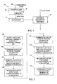
- FIG. 2 is a flow chart illustrating a method for calibrating the actuator system in accordance with an embodiment of the invention
- FIG. 3 is a plot depicting flow rate versus vane position data obtained by testing several turbochargers, and showing a linear two-point calibration based on the data;
- FIG. 4 depicts a two-point calibration table that can be stored in the controller memory.
- FIG. 1 schematically depicts an actuator system 10 for a variable nozzle of a turbocharger.
- the actuator system includes an actuator 12 for being mechanically connected to a variable-geometry member 14 of the nozzle.
- the actuator 12 can be connected to the unison ring via a suitable linkage.
- the actuator 12 can be connected to the piston via a suitable linkage.
- the details of the variable-geometry member and linkage are not important for purposes of the present invention.
- the actuator 12 can be of various types, including linear and rotary actuators.
- the actuator comprises a rotary electric actuator (REA).
- REA rotary electric actuator
- the actuator system also includes an electronic controller 16 for the actuator.
- the controller includes a memory 18 that can store electronic data for use by the controller.
- the controller is configured to be capable of executing operations by manipulating electronic signals.
- the controller can include a microprocessor.
- the controller is able to execute a predetermined set of instructions, or program, which can be implemented in firmware, in software, or in a combination of firmware and software.
- the electronic controller 16 can be incorporated in the actuator 12.
- the controller 16 can be implemented in an engine control unit (ECU) of the internal combustion engine to which the turbocharger is connected.
- ECU engine control unit
- the controller 16 is typically arranged to receive command signals 20 determined in the ECU (not shown) of the internal combustion engine.
- the ECU typically supplies a signal 20 indicative of a commanded or desired flow rate for the turbine of the turbocharger.
- the controller 16 then signals the actuator to move to a position corresponding to the desired flow rate.
- turbochargers of the same nominal design typically vary in terms of nozzle flow characteristics. Accordingly, the relationship between actuator position and nozzle flow rate can differ appreciably from one turbocharger to the next.
- the present invention concerns a method for calibrating the actuator system in order to substantially reduce such variability.
- FIG. 2 is a flow chart showing steps of the method in accordance with one embodiment of the invention.
- the calibration process can be performed with the aid of a flow bench or test stand having the capability of supplying a flow of air to the turbine at a selectively variable super-atmospheric pressure, and of measuring the flow rate of the air and the pressure ratio across the turbine.
- Such flow benches are well known and hence are not further described herein.
- the flow bench is operated to supply air to the turbine.
- the flow bench monitors the pressure ratio across the turbine throughout the calibration process, and continually adjusts the turbine inlet pressure as needed in order to maintain the pressure ratio generally constant, i.e., within a predetermined range.
- the flow bench commands the actuator to move toward a first calibration position.
- the first calibration position may correspond to an 80% closed position of the variable-geometry member of the turbine nozzle, which nominally is designed to produce a predetermined desired turbine flow rate.
- the flow bench commands the actuator to move toward the first calibration position in a series of increments.
- the flow bench monitors the changing flow rate as the variable-geometry member is incrementally moved. As the flow rate approaches the desired flow rate, the flow bench commands the actuator to move in smaller increments, until the measured flow rate is substantially equal to the desired flow rate.
- the commanded actuator position that substantially achieves the desired flow rate is recorded as actuator position #1 (step 106 ).
- the flow bench commands the actuator to move toward a second calibration position.
- the second calibration position may correspond to a 30% closed position of the variable-geometry member of the turbine nozzle, which is nominally designed to produce a predetermined desired flow rate.
- the flow bench monitors the changing flow rate as the variable-geometry member is incrementally moved. As the flow rate approaches the desired flow rate, the flow bench commands the actuator to move in smaller increments, until the measured flow rate is substantially equal to the desired flow rate.
- the commanded actuator position that substantially achieves the desired flow rate is recorded as actuator position #2 (step 112 ).
- steps similar to steps 108-112 can be repeated for one or more additional actuator positions and flow rates.
- the method entails determining at least two actuator positions and corresponding flow rates as shown in FIG. 2 .
- the final step of the calibration method is storing a multi-point calibration in the memory 18 of the controller 16.
- FIG. 3 is a graph showing actual test results obtained by testing a turbocharger on a flow bench generally as illustrated in FIG. 2 .
- the turbocharger had a variable vane mechanism for regulating turbine flow rate.
- the turbine pressure ratio was maintained substantially constant at about 1.25 throughout the tests.
- the solid line represents actual flow rate versus percent vane position (0% representing fully open and 100% representing fully closed). It can be seen that the relationship between flow rate and vane position is substantially linear. Although the data below 30% vane position appear to indicate a somewhat non-linear trend, it is believed that this is a result of limitations of the particular flow bench used for the tests. Other testing using different flow benches has indicated a substantially linear relationship all the way to 0% vane position.
- test data such as shown in FIG. 3 can be used to construct a multi-point calibration for the actuator system of the turbocharger.
- a two-point calibration can be determined as illustrated in FIG. 3 .
- a first calibration point is selected at 30% vane position.
- the test data at 30% vane position indicate the flow rate was about 550 kg/hr.
- a second calibration point is selected at 80% vane position, at which the flow rate was about 280 kg/hr.
- the two-point calibration can be stored in the controller's memory in any suitable form.
- a look-up table such as shown in FIG. 4 can be stored in the memory.
- the table includes two points each having a value for actuator position and a corresponding value for flow rate.
- the controller is programmed to employ a table look-up scheme to determine the actuator position required in order to produce a given flow rate. For instance, if the engine's ECU commands the controller to adjust the variable nozzle to produce a flow rate of 400 kg/hr, the controller employs linear interpolation between point #1 and point #2 to calculate the actuator position as about 57.8% vane position. The controller then sends to the actuator a command signal corresponding to 57.8% vane position.
- a similar calibration can be performed for each turbocharger produced, such that each turbocharger's actuator system has its own multi-point calibration. In this manner, even if the turbochargers vary from one to the next in terms of nozzle flow characteristics, the turbochargers will produce substantially the same nozzle flow rate for a given commanded flow rate from the ECU.
- the simple two-point calibration as described above works well when the nozzle flow rate is substantially linear with vane position. In reality, the flow rate generally is not perfectly linear with vane position. Improved accuracy can be attained by using more than two points for the calibration. For example, a look-up table having three, four, five, or more points can be stored in the controller's memory. The controller can employ a table look-up scheme to interpolate between the stored points.
- the controller's memory can store the multi-point calibration in the form of a curve fit or formula.
- the formula can be a polynomial expression determined using known curve-fitting techniques.
- the procedure described above assumes that the signal 20 ( FIG. 1 ) from the engine's ECU represents a desired flow rate for the turbine.
- the signal 20 can represent a commanded actuator position that is based on a "nominal" relationship between actuator position and flow rate.
- a given turbocharger may have a position-flow relationship that differs from nominal.
- the multi-point calibration in this embodiment can represent a relationship between "nominal" actuator position and actual actuator position for a given flow rate.
Landscapes
- Engineering & Computer Science (AREA)
- Chemical & Material Sciences (AREA)
- Combustion & Propulsion (AREA)
- Mechanical Engineering (AREA)
- General Engineering & Computer Science (AREA)
- Supercharger (AREA)
Applications Claiming Priority (1)
| Application Number | Priority Date | Filing Date | Title |
|---|---|---|---|
| US12/129,343 US7689376B2 (en) | 2008-05-29 | 2008-05-29 | Method of calibrating an actuator system for a variable nozzle of a turbocharger |
Publications (3)
| Publication Number | Publication Date |
|---|---|
| EP2128408A2 true EP2128408A2 (de) | 2009-12-02 |
| EP2128408A3 EP2128408A3 (de) | 2011-04-20 |
| EP2128408B1 EP2128408B1 (de) | 2021-07-07 |
Family
ID=41010578
Family Applications (1)
| Application Number | Title | Priority Date | Filing Date |
|---|---|---|---|
| EP09160949.5A Active EP2128408B1 (de) | 2008-05-29 | 2009-05-22 | Verfahren zur Kalibrierung eines Betätigungssystems für eine variable Düse eines Turboladers und Datenverarbeitungsvorrichtung zur Durchführung solch eines Verfahren |
Country Status (2)
| Country | Link |
|---|---|
| US (1) | US7689376B2 (de) |
| EP (1) | EP2128408B1 (de) |
Cited By (3)
| Publication number | Priority date | Publication date | Assignee | Title |
|---|---|---|---|---|
| EP3070276A1 (de) * | 2015-03-17 | 2016-09-21 | Rolls-Royce Controls and Data Services Limited | Steuerungssystem für verstellbare leitschaufeln |
| WO2017207459A1 (de) * | 2016-05-31 | 2017-12-07 | Robert Bosch Gmbh | Verfahren und vorrichtung zur kalibrierung eines stellgebersystems |
| CN111456844A (zh) * | 2020-04-08 | 2020-07-28 | 重庆江增船舶重工有限公司 | 一种可变几何混流涡轮增压器的控制方法 |
Families Citing this family (8)
| Publication number | Priority date | Publication date | Assignee | Title |
|---|---|---|---|---|
| GB2461553B (en) * | 2008-07-03 | 2012-10-10 | Gm Global Tech Operations Inc | A control method and system for a fluid control device, based on position sensor learning |
| US8931272B2 (en) * | 2010-10-29 | 2015-01-13 | Ford Global Technologies, Llc | Method and system for limiting output of a boosted engine |
| FR2983236B1 (fr) * | 2011-11-24 | 2016-05-06 | Snecma | Procede de surveillance du jeu d'une cinematique de liaison entre un organe de commande et un organe recepteur. |
| KR101441414B1 (ko) | 2013-07-15 | 2014-09-25 | 국방과학연구소 | 가변노즐의 지상 시험장치 |
| GB201405572D0 (en) * | 2014-03-28 | 2014-05-14 | Rolls Royce Plc | Actuation system investigation apparatus |
| CN112627970B (zh) * | 2020-12-24 | 2022-05-13 | 江苏毅合捷汽车科技股份有限公司 | 涡轮增压器vnt气控阀开度位置电压标定工艺及系统 |
| DE102022104501B4 (de) | 2022-02-24 | 2026-02-05 | Rolls-Royce Solutions GmbH | Steuervorrichtung für eine Brennkraftmaschine, Brennkraftmaschinenanordnung mit einer Brennkraftmaschine und einer solchen Steuervorrichtung, Verfahren zum Betreiben einer Brennkraftmaschine, und Verfahren zum Ermitteln eines Komponentenkennfelds |
| NL2031474B1 (en) * | 2022-04-01 | 2023-10-24 | Daf Trucks Nv | Variable geometry turbine and method for calibrating a variable geometry turbine |
Citations (1)
| Publication number | Priority date | Publication date | Assignee | Title |
|---|---|---|---|---|
| US20080011071A1 (en) | 2006-07-17 | 2008-01-17 | Giorgio Figura | Method for calibrating a turbocharger |
Family Cites Families (7)
| Publication number | Priority date | Publication date | Assignee | Title |
|---|---|---|---|---|
| US3893300A (en) * | 1973-04-30 | 1975-07-08 | Nrg Inc | External combustion engine and engine cycle |
| EP1499796B1 (de) * | 2002-02-08 | 2005-08-24 | Honeywell Garrett SA, Garrett Engine Boosting Systems | Betätigungseinrichtung für turbolader |
| DE10233951B4 (de) * | 2002-07-25 | 2010-06-24 | Continental Automotive Gmbh | Verfahren zur Adaption eines Stellstreckenmodells für einen Abgasturboladersteller |
| JP4244198B2 (ja) * | 2004-03-15 | 2009-03-25 | トヨタ自動車株式会社 | 内燃機関の燃料噴射制御方法 |
| EP1703110A1 (de) * | 2005-03-18 | 2006-09-20 | Ford Global Technologies, LLC, A subsidary of Ford Motor Company | Verfahren zur Optimierung der Kalibrierung eines Verbrennungsmotors |
| JP2007315632A (ja) * | 2006-05-23 | 2007-12-06 | Denso Corp | エジェクタ式サイクル |
| US8523511B2 (en) * | 2007-11-13 | 2013-09-03 | Honeywell International Inc. | Adaptive variable geometry turbocharger strategy |
-
2008
- 2008-05-29 US US12/129,343 patent/US7689376B2/en active Active
-
2009
- 2009-05-22 EP EP09160949.5A patent/EP2128408B1/de active Active
Patent Citations (1)
| Publication number | Priority date | Publication date | Assignee | Title |
|---|---|---|---|---|
| US20080011071A1 (en) | 2006-07-17 | 2008-01-17 | Giorgio Figura | Method for calibrating a turbocharger |
Cited By (6)
| Publication number | Priority date | Publication date | Assignee | Title |
|---|---|---|---|---|
| EP3070276A1 (de) * | 2015-03-17 | 2016-09-21 | Rolls-Royce Controls and Data Services Limited | Steuerungssystem für verstellbare leitschaufeln |
| US10132189B2 (en) | 2015-03-17 | 2018-11-20 | Rolls-Royce Plc | Variable vane control system |
| WO2017207459A1 (de) * | 2016-05-31 | 2017-12-07 | Robert Bosch Gmbh | Verfahren und vorrichtung zur kalibrierung eines stellgebersystems |
| US11175163B2 (en) | 2016-05-31 | 2021-11-16 | Robert Bosch Gmbh | Method and apparatus for calibrating an actuator system |
| CN111456844A (zh) * | 2020-04-08 | 2020-07-28 | 重庆江增船舶重工有限公司 | 一种可变几何混流涡轮增压器的控制方法 |
| CN111456844B (zh) * | 2020-04-08 | 2021-04-02 | 重庆江增船舶重工有限公司 | 一种可变几何混流涡轮增压器的控制方法 |
Also Published As
| Publication number | Publication date |
|---|---|
| EP2128408A3 (de) | 2011-04-20 |
| US20090299673A1 (en) | 2009-12-03 |
| US7689376B2 (en) | 2010-03-30 |
| EP2128408B1 (de) | 2021-07-07 |
Similar Documents
| Publication | Publication Date | Title |
|---|---|---|
| US7689376B2 (en) | Method of calibrating an actuator system for a variable nozzle of a turbocharger | |
| US6928817B2 (en) | Control system for improved transient response in a variable-geometry turbocharger | |
| CN106321252B (zh) | 一种航空发动机的起动过程燃油控制方法和系统 | |
| US9322323B2 (en) | Method for correcting the reduced mass flow rate of a compressor in an internal combustion engine turbocharged with a turbocharger | |
| US8302397B2 (en) | Mode transition systems and methods for a sequential turbocharger | |
| JP7201698B2 (ja) | 内燃機関をモデルに基づき開ループ制御及び閉ループ制御する方法 | |
| JP5627733B1 (ja) | 内燃機関のウエストゲートバルブ制御装置および内燃機関のウエストゲートバルブ制御方法 | |
| EP1533573A1 (de) | Verfahren zur Regelung der Brennstoffverteilung einer Gasturbinenbrennkammer | |
| JP4585277B2 (ja) | 質量流導管内の少なくとも一つのアクチュエータの制御方法 | |
| KR101910294B1 (ko) | 조절 장치를 갖는 내연기관 | |
| CN103518047A (zh) | 增压发动机的控制装置 | |
| WO2007106703A1 (en) | Control for variable geometry compressor | |
| CN107269407B (zh) | 用于确定燃烧马达中的新鲜空气质量流量的方法和装置 | |
| CN101105152A (zh) | 用于对内燃机进行增压调节的方法 | |
| CN104632359B (zh) | 用于控制涡轮增压内燃发动机中的排气泄压阀的方法 | |
| JP2007127121A (ja) | 特に自動車の内燃機関エンジン用の、可変ターボチャージャーの形状を制御するための方法及び装置 | |
| US20130025275A1 (en) | Method and device for adjusting an end position of a turbine for a charging device having a variable turbine geometry | |
| KR20050094756A (ko) | 내연 기관 제어 방법 | |
| DE10007669B4 (de) | Verfahren zur Regelung eines Verdichters, insbesondere eines Verdichters im Ansaugtrakt einer Brennkraftmaschine | |
| SE526009C2 (sv) | Förfarande och anordning för reglering av laddningstrycket hos åtminstone två kompressorer till en förbränningsmotor | |
| EP1302644B1 (de) | Verfahren zur Steuerung eines Abgasturboladers mit verstellbarer Turbinengeometrie | |
| EP3892830A1 (de) | Modellierung und steuerung des betriebes eines gas-kreislauf-kraftwerks durch variation der geteilten last für mehrere gasturbinen | |
| RU2653262C2 (ru) | Способ управления газотурбинным двигателем и система для его осуществления | |
| CN115717553A (zh) | 喷嘴环组开度控制方法及废气涡轮增压系统 | |
| KR101186222B1 (ko) | 차량용 터보차저의 제어방법 및 이를 이용한 터보자처 |
Legal Events
| Date | Code | Title | Description |
|---|---|---|---|
| PUAI | Public reference made under article 153(3) epc to a published international application that has entered the european phase |
Free format text: ORIGINAL CODE: 0009012 |
|
| 17P | Request for examination filed |
Effective date: 20090522 |
|
| AK | Designated contracting states |
Kind code of ref document: A2 Designated state(s): AT BE BG CH CY CZ DE DK EE ES FI FR GB GR HR HU IE IS IT LI LT LU LV MC MK MT NL NO PL PT RO SE SI SK TR |
|
| PUAL | Search report despatched |
Free format text: ORIGINAL CODE: 0009013 |
|
| AK | Designated contracting states |
Kind code of ref document: A3 Designated state(s): AT BE BG CH CY CZ DE DK EE ES FI FR GB GR HR HU IE IS IT LI LT LU LV MC MK MT NL NO PL PT RO SE SI SK TR |
|
| 17Q | First examination report despatched |
Effective date: 20110331 |
|
| RAP1 | Party data changed (applicant data changed or rights of an application transferred) |
Owner name: HONEYWELL INTERNATIONAL INC. |
|
| STAA | Information on the status of an ep patent application or granted ep patent |
Free format text: STATUS: EXAMINATION IS IN PROGRESS |
|
| RAP1 | Party data changed (applicant data changed or rights of an application transferred) |
Owner name: GARRETT TRANSPORTATION I INC. |
|
| REG | Reference to a national code |
Ref country code: DE Ref legal event code: R079 Ref document number: 602009063852 Country of ref document: DE Free format text: PREVIOUS MAIN CLASS: F02D0023020000 Ipc: F02B0037240000 |
|
| GRAP | Despatch of communication of intention to grant a patent |
Free format text: ORIGINAL CODE: EPIDOSNIGR1 |
|
| STAA | Information on the status of an ep patent application or granted ep patent |
Free format text: STATUS: GRANT OF PATENT IS INTENDED |
|
| RIC1 | Information provided on ipc code assigned before grant |
Ipc: F02D 41/14 20060101ALI20201127BHEP Ipc: F02D 41/24 20060101ALI20201127BHEP Ipc: F02B 37/24 20060101AFI20201127BHEP Ipc: F02D 41/00 20060101ALI20201127BHEP Ipc: F02D 43/02 20060101ALI20201127BHEP Ipc: F02B 39/16 20060101ALI20201127BHEP |
|
| INTG | Intention to grant announced |
Effective date: 20201223 |
|
| GRAS | Grant fee paid |
Free format text: ORIGINAL CODE: EPIDOSNIGR3 |
|
| GRAA | (expected) grant |
Free format text: ORIGINAL CODE: 0009210 |
|
| STAA | Information on the status of an ep patent application or granted ep patent |
Free format text: STATUS: THE PATENT HAS BEEN GRANTED |
|
| AK | Designated contracting states |
Kind code of ref document: B1 Designated state(s): AT BE BG CH CY CZ DE DK EE ES FI FR GB GR HR HU IE IS IT LI LT LU LV MC MK MT NL NO PL PT RO SE SI SK TR |
|
| REG | Reference to a national code |
Ref country code: GB Ref legal event code: FG4D |
|
| REG | Reference to a national code |
Ref country code: AT Ref legal event code: REF Ref document number: 1408800 Country of ref document: AT Kind code of ref document: T Effective date: 20210715 |
|
| REG | Reference to a national code |
Ref country code: DE Ref legal event code: R096 Ref document number: 602009063852 Country of ref document: DE |
|
| REG | Reference to a national code |
Ref country code: IE Ref legal event code: FG4D |
|
| REG | Reference to a national code |
Ref country code: LT Ref legal event code: MG9D |
|
| REG | Reference to a national code |
Ref country code: NL Ref legal event code: MP Effective date: 20210707 |
|
| REG | Reference to a national code |
Ref country code: AT Ref legal event code: MK05 Ref document number: 1408800 Country of ref document: AT Kind code of ref document: T Effective date: 20210707 |
|
| PG25 | Lapsed in a contracting state [announced via postgrant information from national office to epo] |
Ref country code: HR Free format text: LAPSE BECAUSE OF FAILURE TO SUBMIT A TRANSLATION OF THE DESCRIPTION OR TO PAY THE FEE WITHIN THE PRESCRIBED TIME-LIMIT Effective date: 20210707 Ref country code: SE Free format text: LAPSE BECAUSE OF FAILURE TO SUBMIT A TRANSLATION OF THE DESCRIPTION OR TO PAY THE FEE WITHIN THE PRESCRIBED TIME-LIMIT Effective date: 20210707 Ref country code: NO Free format text: LAPSE BECAUSE OF FAILURE TO SUBMIT A TRANSLATION OF THE DESCRIPTION OR TO PAY THE FEE WITHIN THE PRESCRIBED TIME-LIMIT Effective date: 20211007 Ref country code: PT Free format text: LAPSE BECAUSE OF FAILURE TO SUBMIT A TRANSLATION OF THE DESCRIPTION OR TO PAY THE FEE WITHIN THE PRESCRIBED TIME-LIMIT Effective date: 20211108 Ref country code: NL Free format text: LAPSE BECAUSE OF FAILURE TO SUBMIT A TRANSLATION OF THE DESCRIPTION OR TO PAY THE FEE WITHIN THE PRESCRIBED TIME-LIMIT Effective date: 20210707 Ref country code: FI Free format text: LAPSE BECAUSE OF FAILURE TO SUBMIT A TRANSLATION OF THE DESCRIPTION OR TO PAY THE FEE WITHIN THE PRESCRIBED TIME-LIMIT Effective date: 20210707 Ref country code: ES Free format text: LAPSE BECAUSE OF FAILURE TO SUBMIT A TRANSLATION OF THE DESCRIPTION OR TO PAY THE FEE WITHIN THE PRESCRIBED TIME-LIMIT Effective date: 20210707 Ref country code: AT Free format text: LAPSE BECAUSE OF FAILURE TO SUBMIT A TRANSLATION OF THE DESCRIPTION OR TO PAY THE FEE WITHIN THE PRESCRIBED TIME-LIMIT Effective date: 20210707 Ref country code: BG Free format text: LAPSE BECAUSE OF FAILURE TO SUBMIT A TRANSLATION OF THE DESCRIPTION OR TO PAY THE FEE WITHIN THE PRESCRIBED TIME-LIMIT Effective date: 20211007 Ref country code: LT Free format text: LAPSE BECAUSE OF FAILURE TO SUBMIT A TRANSLATION OF THE DESCRIPTION OR TO PAY THE FEE WITHIN THE PRESCRIBED TIME-LIMIT Effective date: 20210707 |
|
| PG25 | Lapsed in a contracting state [announced via postgrant information from national office to epo] |
Ref country code: PL Free format text: LAPSE BECAUSE OF FAILURE TO SUBMIT A TRANSLATION OF THE DESCRIPTION OR TO PAY THE FEE WITHIN THE PRESCRIBED TIME-LIMIT Effective date: 20210707 Ref country code: LV Free format text: LAPSE BECAUSE OF FAILURE TO SUBMIT A TRANSLATION OF THE DESCRIPTION OR TO PAY THE FEE WITHIN THE PRESCRIBED TIME-LIMIT Effective date: 20210707 Ref country code: GR Free format text: LAPSE BECAUSE OF FAILURE TO SUBMIT A TRANSLATION OF THE DESCRIPTION OR TO PAY THE FEE WITHIN THE PRESCRIBED TIME-LIMIT Effective date: 20211008 |
|
| REG | Reference to a national code |
Ref country code: DE Ref legal event code: R097 Ref document number: 602009063852 Country of ref document: DE |
|
| PG25 | Lapsed in a contracting state [announced via postgrant information from national office to epo] |
Ref country code: DK Free format text: LAPSE BECAUSE OF FAILURE TO SUBMIT A TRANSLATION OF THE DESCRIPTION OR TO PAY THE FEE WITHIN THE PRESCRIBED TIME-LIMIT Effective date: 20210707 |
|
| PLBE | No opposition filed within time limit |
Free format text: ORIGINAL CODE: 0009261 |
|
| STAA | Information on the status of an ep patent application or granted ep patent |
Free format text: STATUS: NO OPPOSITION FILED WITHIN TIME LIMIT |
|
| PG25 | Lapsed in a contracting state [announced via postgrant information from national office to epo] |
Ref country code: SK Free format text: LAPSE BECAUSE OF FAILURE TO SUBMIT A TRANSLATION OF THE DESCRIPTION OR TO PAY THE FEE WITHIN THE PRESCRIBED TIME-LIMIT Effective date: 20210707 Ref country code: RO Free format text: LAPSE BECAUSE OF FAILURE TO SUBMIT A TRANSLATION OF THE DESCRIPTION OR TO PAY THE FEE WITHIN THE PRESCRIBED TIME-LIMIT Effective date: 20210707 Ref country code: EE Free format text: LAPSE BECAUSE OF FAILURE TO SUBMIT A TRANSLATION OF THE DESCRIPTION OR TO PAY THE FEE WITHIN THE PRESCRIBED TIME-LIMIT Effective date: 20210707 Ref country code: CZ Free format text: LAPSE BECAUSE OF FAILURE TO SUBMIT A TRANSLATION OF THE DESCRIPTION OR TO PAY THE FEE WITHIN THE PRESCRIBED TIME-LIMIT Effective date: 20210707 |
|
| 26N | No opposition filed |
Effective date: 20220408 |
|
| PG25 | Lapsed in a contracting state [announced via postgrant information from national office to epo] |
Ref country code: IT Free format text: LAPSE BECAUSE OF FAILURE TO SUBMIT A TRANSLATION OF THE DESCRIPTION OR TO PAY THE FEE WITHIN THE PRESCRIBED TIME-LIMIT Effective date: 20210707 |
|
| REG | Reference to a national code |
Ref country code: CH Ref legal event code: PL |
|
| REG | Reference to a national code |
Ref country code: BE Ref legal event code: MM Effective date: 20220531 |
|
| PG25 | Lapsed in a contracting state [announced via postgrant information from national office to epo] |
Ref country code: MC Free format text: LAPSE BECAUSE OF FAILURE TO SUBMIT A TRANSLATION OF THE DESCRIPTION OR TO PAY THE FEE WITHIN THE PRESCRIBED TIME-LIMIT Effective date: 20210707 Ref country code: LU Free format text: LAPSE BECAUSE OF NON-PAYMENT OF DUE FEES Effective date: 20220522 Ref country code: LI Free format text: LAPSE BECAUSE OF NON-PAYMENT OF DUE FEES Effective date: 20220531 Ref country code: CH Free format text: LAPSE BECAUSE OF NON-PAYMENT OF DUE FEES Effective date: 20220531 |
|
| PG25 | Lapsed in a contracting state [announced via postgrant information from national office to epo] |
Ref country code: IE Free format text: LAPSE BECAUSE OF NON-PAYMENT OF DUE FEES Effective date: 20220522 |
|
| PG25 | Lapsed in a contracting state [announced via postgrant information from national office to epo] |
Ref country code: BE Free format text: LAPSE BECAUSE OF NON-PAYMENT OF DUE FEES Effective date: 20220531 |
|
| P01 | Opt-out of the competence of the unified patent court (upc) registered |
Effective date: 20230424 |
|
| PG25 | Lapsed in a contracting state [announced via postgrant information from national office to epo] |
Ref country code: HU Free format text: LAPSE BECAUSE OF FAILURE TO SUBMIT A TRANSLATION OF THE DESCRIPTION OR TO PAY THE FEE WITHIN THE PRESCRIBED TIME-LIMIT; INVALID AB INITIO Effective date: 20090522 |
|
| PG25 | Lapsed in a contracting state [announced via postgrant information from national office to epo] |
Ref country code: MK Free format text: LAPSE BECAUSE OF FAILURE TO SUBMIT A TRANSLATION OF THE DESCRIPTION OR TO PAY THE FEE WITHIN THE PRESCRIBED TIME-LIMIT Effective date: 20210707 Ref country code: CY Free format text: LAPSE BECAUSE OF FAILURE TO SUBMIT A TRANSLATION OF THE DESCRIPTION OR TO PAY THE FEE WITHIN THE PRESCRIBED TIME-LIMIT Effective date: 20210707 |
|
| PG25 | Lapsed in a contracting state [announced via postgrant information from national office to epo] |
Ref country code: MT Free format text: LAPSE BECAUSE OF FAILURE TO SUBMIT A TRANSLATION OF THE DESCRIPTION OR TO PAY THE FEE WITHIN THE PRESCRIBED TIME-LIMIT Effective date: 20210707 |
|
| PGFP | Annual fee paid to national office [announced via postgrant information from national office to epo] |
Ref country code: DE Payment date: 20250528 Year of fee payment: 17 |
|
| PGFP | Annual fee paid to national office [announced via postgrant information from national office to epo] |
Ref country code: GB Payment date: 20250520 Year of fee payment: 17 |
|
| PGFP | Annual fee paid to national office [announced via postgrant information from national office to epo] |
Ref country code: FR Payment date: 20250526 Year of fee payment: 17 |
|
| PG25 | Lapsed in a contracting state [announced via postgrant information from national office to epo] |
Ref country code: TR Free format text: LAPSE BECAUSE OF FAILURE TO SUBMIT A TRANSLATION OF THE DESCRIPTION OR TO PAY THE FEE WITHIN THE PRESCRIBED TIME-LIMIT Effective date: 20210707 |