EP2128446A2 - Unité hydraulique - Google Patents
Unité hydraulique Download PDFInfo
- Publication number
- EP2128446A2 EP2128446A2 EP09006984A EP09006984A EP2128446A2 EP 2128446 A2 EP2128446 A2 EP 2128446A2 EP 09006984 A EP09006984 A EP 09006984A EP 09006984 A EP09006984 A EP 09006984A EP 2128446 A2 EP2128446 A2 EP 2128446A2
- Authority
- EP
- European Patent Office
- Prior art keywords
- hydraulic
- pump
- motor
- housing
- unit according
- Prior art date
- Legal status (The legal status is an assumption and is not a legal conclusion. Google has not performed a legal analysis and makes no representation as to the accuracy of the status listed.)
- Granted
Links
Images




Classifications
-
- F—MECHANICAL ENGINEERING; LIGHTING; HEATING; WEAPONS; BLASTING
- F04—POSITIVE - DISPLACEMENT MACHINES FOR LIQUIDS; PUMPS FOR LIQUIDS OR ELASTIC FLUIDS
- F04C—ROTARY-PISTON, OR OSCILLATING-PISTON, POSITIVE-DISPLACEMENT MACHINES FOR LIQUIDS; ROTARY-PISTON, OR OSCILLATING-PISTON, POSITIVE-DISPLACEMENT PUMPS
- F04C2/00—Rotary-piston machines or pumps
- F04C2/08—Rotary-piston machines or pumps of intermeshing-engagement type, i.e. with engagement of co-operating members similar to that of toothed gearing
- F04C2/10—Rotary-piston machines or pumps of intermeshing-engagement type, i.e. with engagement of co-operating members similar to that of toothed gearing of internal-axis type with the outer member having more teeth or tooth-equivalents, e.g. rollers, than the inner member
-
- F—MECHANICAL ENGINEERING; LIGHTING; HEATING; WEAPONS; BLASTING
- F04—POSITIVE - DISPLACEMENT MACHINES FOR LIQUIDS; PUMPS FOR LIQUIDS OR ELASTIC FLUIDS
- F04C—ROTARY-PISTON, OR OSCILLATING-PISTON, POSITIVE-DISPLACEMENT MACHINES FOR LIQUIDS; ROTARY-PISTON, OR OSCILLATING-PISTON, POSITIVE-DISPLACEMENT PUMPS
- F04C11/00—Combinations of two or more machines or pumps, each being of rotary-piston or oscillating-piston type; Pumping installations
- F04C11/005—Combinations of two or more machines or pumps, each being of rotary-piston or oscillating-piston type; Pumping installations of dissimilar working principle
-
- F—MECHANICAL ENGINEERING; LIGHTING; HEATING; WEAPONS; BLASTING
- F04—POSITIVE - DISPLACEMENT MACHINES FOR LIQUIDS; PUMPS FOR LIQUIDS OR ELASTIC FLUIDS
- F04C—ROTARY-PISTON, OR OSCILLATING-PISTON, POSITIVE-DISPLACEMENT MACHINES FOR LIQUIDS; ROTARY-PISTON, OR OSCILLATING-PISTON, POSITIVE-DISPLACEMENT PUMPS
- F04C2210/00—Fluid
- F04C2210/14—Lubricant
-
- F—MECHANICAL ENGINEERING; LIGHTING; HEATING; WEAPONS; BLASTING
- F04—POSITIVE - DISPLACEMENT MACHINES FOR LIQUIDS; PUMPS FOR LIQUIDS OR ELASTIC FLUIDS
- F04C—ROTARY-PISTON, OR OSCILLATING-PISTON, POSITIVE-DISPLACEMENT MACHINES FOR LIQUIDS; ROTARY-PISTON, OR OSCILLATING-PISTON, POSITIVE-DISPLACEMENT PUMPS
- F04C2240/00—Components
- F04C2240/30—Casings or housings
Definitions
- the invention / innovation relates to a hydraulic unit for providing a pressurized hydraulic fluid for driving a coupled hydraulic actuator, comprising a motor arranged in a pressurized motor housing, a hydraulic accumulator arranged in a storage housing, a hydraulic pump disposed in a pump housing and a hydraulic block, wherein at least the motor housing, pump housing and the hydraulic block form a uniform manageable rigid module and the hydraulic fluid flowing around in the module passes through all the elements of the module in the longitudinal direction (circulation system) in some areas.
- WO 2006/056256 A2 teaches a hydraulic power unit, which uses an electric motor and a pump operated via this for generating pressure to a pressurized hydraulic fluid at an output.
- the hydraulic fluid drawn in by the pump is provided with a storage space with a variable compensation volume, in which the hydraulic fluid is stored gas-free.
- the invention / innovation is the object of developing a hydraulic unit with the features of the preamble of claim 1 such that it can be realized in a compact design, controlled by the simplest control and regulated (without electric valves) can be and has good operating characteristics such as high rigidity, overload safety and low noise emission. It is another object of the invention to have both good adaptability to, for example, extreme cold, ways and speeds as well as a high degree of flexibility.
- the hydraulic pump and the hydraulic block form a functional unit
- the hydraulic block is provided with a plurality of hydraulic connection elements and a flange arranged in the pump housing delivery chamber is covered by the hydraulic block on the opposite side of the motor housing.
- the arrangement of the hydraulic pump immediately adjacent to the hydraulic block allows both a manufacturing technology easy to implement, as well as reliably operable in operation functional unit.
- the integration of the delivery chamber of the pump final "lid" to the hydraulic block the dimensioning of the entire hydraulic unit is reduced. Parts of the pump components are assigned to the hydraulic unit. Both in the pump housing, as well as in the hydraulic block valves can be integrated.
- the hydraulic connection elements serve as an interface of the hydraulic unit to the connecting lines of the hydraulic actuators to be driven.
- the hydraulic accumulator can be part of the uniform, manageable rigid module, thus reducing the dimensioning of the entire unit.
- the hydraulic fluid flowing through all the elements of the module in the longitudinal direction is preferably guided in one circulation.
- This can be the Hydraulic fluid also be assigned a cooling function in addition to the power transmission.
- hydraulic elements such as pressure relief valves, suction valves or pilot operated check valves may be integrally employed and assisted by the shape and shape of the channels in the pump housing (e.g., channeling and / or concentration of hydraulic fluid in the area of the valves used).
- the immediate vicinity of the hydraulic block to the pump achieves design advantages, it can be ensured directly from the pump delivery chamber via shortest connections to the hydraulic connection elements and optionally between these intermediate overload valves / pressure relief valves a safe, reliable and energy-saving operation of the hydraulic unit ,
- circumferential elements of the hydraulic pump protrude into the region of the hydraulic block via the flange surface arranged between the pump housing and the hydraulic block in the delivery chamber.
- shaft elements (pinion shaft) of the pump can be mounted at least in regions in a corresponding recess of the hydraulic block.
- the dimensioning of the entire hydraulic unit is further reduced.
- the rotating elements of the hydraulic pump are guided in the region of the hydraulic block.
- Such a guide can positively affect both the storage and optionally other functions of the pump shaft to elements of the hydraulic block, for example, the pump shaft is formed as a hollow shaft, which in a continuing, preferably hydraulic fluid leading channel of the hydraulic block continues.
- the peripheral elements arranged in the pump housing, cooperating therewith, valve elements arranged in the pump housing and the valve elements of the hydraulic block form a coherent integrated hydraulic functional unit.
- the surface of the hydraulic block facing the pump does not only have a function concluding the delivery chamber, but also has further recesses influencing the function of the pump and / or the hydraulic fluid management, control and / or regulation.
- the fact that there is a connection to the pump directly from the valve elements of the hydraulic block both a structurally simple, and low-maintenance and thus a reliable hydraulic unit is provided, for example, the sealed areas can be reduced to a minimum (only static seals).
- the pump is designed such that it is operable in four-quadrant mode and thereby allows a promotion of the hydraulic fluid in two directions (forward / backward).
- This also makes it possible, for example, not only to use the hydraulic unit as a medium providing hydraulic pressure, but also to tap from this electrical energy when the hydraulic unit is acted upon by a hydraulic pressure (energy return - 2, and 4 th quadrant).
- the pump is designed as a gear pump.
- This includes, for example, an external gear, internal gear or gerotor pump.
- Vane pumps, screw pumps, rotary lobe pumps or rotary vane pumps can also be used in conjunction with the hydraulic unit.
- Such pumps have the advantage that they are a relative ensure uniform delivery of the pump medium and the conveying direction is reversible with the direction of rotation.
- drive modes for the motor are preferably called controlled or unregulated electrical asynchronous or synchronous motors.
- drive modes for the motor are preferably called controlled or unregulated electrical asynchronous or synchronous motors.
- under oil designs are preferred which ensure intensive cooling, build compact and achieve a low mass moment of inertia.
- a further hydraulic pump is arranged, which is also driven by the motor.
- the further hydraulic pump can be arranged between the motor and the hydraulic accumulator and / or between the first pump and the hydraulic block and can likewise be driven via the motor driving the first hydraulic pump.
- higher pressures for the hydraulic medium can be generated.
- the pump power especially at high Press
- a hydraulic pump can be designed as a radial piston pump and arranged both on the pump and preferably on the storage side of the engine. Since this has a favorable efficiency and reaches high load pressures at a smaller flow rate, it is suitable for the above-described Forming and / or shear phases. Consequently, the radial piston pump can serve primarily as a second higher pressure level. In order to be able to use the full drive power for the high pressures, the delivery of the low-pressure pump is automatically switched to pressureless circulation.
- the leak hydraulic fluid occurring during operation of the hydraulic unit is preferably returned directly to the housing in the hydraulic system of the hydraulic unit.
- the hydraulic fluid exiting from one or more pressure relief valves and / or other hydraulic elements may be internally fed directly into the hydraulic system of the hydraulic unit.
- This pressure limiting valve and / or hydraulic element is preferably arranged in the region of the hydraulic block and is operatively connected to channels arranged in the region of the pressure limiting valve and / or hydraulic element, which purposefully recirculate the escaping hydraulic fluid into the hydraulic system of the hydraulic unit. This can also be used for one circulation to maintain the cooling.
- a hydraulic return line is formed, which connects the outlet of the pressure limiting valve with the hydraulic reservoir passing through the engine and hydraulic accumulator.
- a hydraulic return flow channel is preferably operatively connected directly or indirectly to the pressure limiting valve and / or hydraulic element.
- the shaft of the motor and / or the shaft of the pump as Hollow shaft formed and forms a part of the return channel (circulation channel) for the hydraulic fluid to return them to the hydraulic accumulator.
- both the dimensioning of the entire hydraulic unit can be reduced, as well as a cooling function are taken over by the flowing back through the return flow in the hydraulic fluid, as this when flowing through the motor and / or pump hollow shaft to just this place, but especially at the stator and rotor of the engine can dissipate heat energy.
- a particularly advantageous embodiment of the hydraulic unit according to the invention is formed in that the return flow channel formed by the shaft of the motor is aligned coaxially with the hydraulic return flow of the pump.
- Such a linear hydraulic fluid stirring simplifies the overall construction, reduces the resistances acting on the hydraulic fluid and promotes or allows the hydraulic fluid circulation.
- the return flow channel formed by the shaft of the engine immediately continues with the volume of the hydraulic accumulator.
- the opposing flanges of the pump housing are aligned parallel to each other.
- these flanges are aligned parallel to each other and / or have a coordinated coupling surface, it is possible, in the manner of a modular system, one, two or more pump housing together and thus designed depending on the application, the performance of the hydraulic unit targeted.
- a coupling element such as a cross slide.
- a coupling element may be formed depending on the combination of different motors and different pumps as a specific combination part, so that at the interfaces of the engine and the pump relatively simple held, the respective component conditions corresponding configurations of the interfaces can be implemented.
- a first coupling element for connecting the two elements can be used and in a second combination case in the combination of a second motor with again the first pump, a second coupling element can be used.
- Such a composition of the individual hydraulic units with such coupling elements increases the flexibility and simplifies the overall construction in particular when providing a plurality of different power gradations (motor-pump combination).
- the coupling element In combination with the central hydraulic fluid return, the coupling element has corresponding recesses and / or openings. In addition, such a coupling compensates for a possible axial offset due to manufacturing tolerances.
- connecting flange passing through hydraulic fluid carrying elements substantially symmetrical to the motor axis.
- hydraulic block, the pump housing, the motor housing and the storage housing are formed substantially rotationally symmetrical and are arranged coaxially or axially parallel to each other.
- the pump housing and / or the motor housing in each case with at least one region beyond the outer diameter of the pump housing or the motor housing final pump flange respectively motor flange area is provided.
- the Pumpenflanschbereieh and the motor flange area advantageously have at least one mounted in a coplanar plane mounting flange on which the substantially cylindrical hydraulic unit is reliably and statically determined mounted on a flat surface.
- the hydraulic accumulator used is preferably a bladder accumulator or a piston accumulator which has an air or gas bias directed against the hydraulic reservoir.
- the bladder accumulator or piston accumulator can also be preloaded with a different preloading element (for example a spring).
- a bladder accumulator having at least one air or gas bias directed against the hydraulic reservoir has the advantage that by controlling and regulating the air or gas bias (e.g., from a pneumatic network), the operation of the hydraulic unit can be selectively influenced.
- a terminal adapter with hydraulic connection elements can be attached to the hydraulic block.
- a cover housing element can be attached to the hydraulic block, which covers at least one valve element.
- various modular attachment to the hydraulic block connection adapter can be arranged on the hydraulic block.
- the hydraulic connection elements of the hydraulic block are then formed by the hydraulic connection elements of the connection adapter. Actuators can be directly connected with suitable flanges, so that the hydraulic unit forms a unit with the actuator.
- the hydraulic unit is designed in such a way that no outwardly acting seals are arranged on moving parts. This is achieved inter alia by the encapsulated, guided in the manner of a circulation hydraulic fluid.
- the flow and return of a hydraulic actuator can be accomplished by only a reversal of the pump rotation of the hydraulic unit.
- a forward and reverse flow can be realized without the use of electromagnetic directional control valves.
- the hydraulic unit is a closed to the atmosphere system and makes it possible to adjust the pressure of different sizes variable. This prevents re-suction (from the atmosphere) and effectively excludes the absorption of air, moisture and foaming harmful to the operation of hydraulic systems.
- the hydraulic actuators perform linear and / or rotary movements.
- the unit for decentralized drives can be provided and position independent, stationary and in particular mobile operation with high accelerations (eg mounting on a robot).
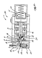
- hydraulic unit 1 is (not shown) for driving a coupled hydraulic actuator driven by a arranged in a motor housing 2 electric motor 3.
- a storage housing 4 is flanged with a hydraulic accumulator 5 arranged therein.
- a hydraulic accumulator 5 is arranged in a pump housing 6 hydraulic pump 7 and on the pump housing 5, a hydraulic block 8 is attached.
- hydraulic connection elements 9 interfaces
- the motor housing 2, the pump housing 6, the hydraulic block 8 and the storage housing 4 form a uniformly hand-held rigid module 30, wherein the hydraulic fluid flowing around in the module 30 passes through all the elements of the module 30 in the longitudinal direction.
- a functional unit is formed.
- the arranged in the pump housing 6 delivery chamber 10 is covered on the motor housing 2 opposite side by the hydraulic block 8.
- the hydraulic accumulator 5 is part of the uniformly manageable rigid module 30th
- the hydraulic unit 1 is shown in longitudinal section. It can be seen in particular that the hydraulic fluid in the longitudinal direction of all elements 3, 5, 7, 8 of the module 30 in its longitudinal direction flowed through in a circular manner. This can be used inter alia that leak hydraulic fluid inside the housing directly into the hydraulic system of the hydraulic unit 1 is traceable.
- the exiting from the pressure relief valves 11 hydraulic fluid inside the housing can be returned directly into the hydraulic system of the hydraulic unit 1. This can be achieved, in particular, by means of a hydraulic return flow channel 12 which is arranged in the central region Z of the hydraulic pump 7, whereby the latter connects the outlet 13 of a pressure limiting valve 11 and / or a pilot operated check valve (not shown) with a hydraulic reservoir passing through the motor 3.
- the hydraulic reservoir is formed, in particular, by the volume area penetrated by the hydraulic fluid, wherein the largest hydraulic reservoir volume can be found in the region of the hydraulic accumulator 5.
- the motor 3 has a hollow shaft 14, which is used as reflux channel 12 for the hydraulic fluid to the hydraulic accumulator 5.
- the hollow shaft 14 it is advantageous, as shown, to connect coaxially with the Hydraulik Wegflußkanal 12 (hollow shaft 15) of the hydraulic pump 7.
- the hydraulic return passage 12 with its hollow shafts 14, 15 is directly connected to the volume of the hydraulic accumulator 5.
- the axes of rotation of the rotating elements of the hydraulic pump 7 and the electric motor 3 are arranged coaxially with each other. If the two hollow shafts 14, 15 of the motor 3 and the hydraulic pump 7 are aligned coaxially with each other, they can be coupled together by a connecting sleeve 16 in such a way that the circulation of the hydraulic fluid is not disturbed.
- the hydraulic accumulator 5 comprises a bladder accumulator, which at its end remote from the motor 3 end 17 with a It is also possible to operate, in particular, from the sectional representation (FIG. Fig. 2 ) can be seen that on the moving parts (hollow shafts 14, 15 and bearing elements of the motor 3 and the hydraulic accumulator 5) no outwardly acting seals are arranged.
- the pump housing 6 is wholly or partially provided with hydraulic elements (valves, channels). Because in Fig. 2 In some cases the (hidden) elements lying behind the cut surfaces are shown visually (dot-dash line S), the connecting channels 18 arranged in the region of the connection surface of the hydraulic block 8 and the hydraulic pump 7 as well as parts of the delivery chambers 10 of the hydraulic pump 7 are visible. The connecting channels 18 and parts of the delivery chamber 10 are thus incorporated as hydraulic elements in the pump housing 6.
- the hydraulic block 8 is shown cut, it is easy to see how the pressure relief valve 11 is disposed within the hydraulic block 8 and how the outgoing from the pump connecting channels 18th and the central hydraulic fluid return passage 12 leads from the hydraulic block 8 to the hollow shafts 14, 15.
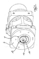
- 8 additional attachments 21, 22 can be seen on the hydraulic block.
- the hydraulic block 8 is viewed from the side view in cross-section T-shaped.
- a cover housing element 21 can be attached to the hydraulic block 8 in such a way that it at least partially covers the hydraulic block 8 as well as optionally valves 11 connected to the hydraulic block 8 and projecting beyond its contour.
- the hydraulic connection elements 9 associated with the hydraulic block 8 are arranged in the illustrated embodiment on the connection adapter 22 and connected by means of channels to the hydraulic block 8.
- connection adapter 22 serves as an adapter to the different connection options due to different connection line connections of the actuators used in each case (line diameter, Amchluß Klipuseelement 21 and / or the terminal adapter 22, it is possible to keep the hydraulic block 8 manufacturing technology simple and to run it as a series part.
- the application-specific interfaces can be assigned to the modular adapters 22 which can be attached to the hydraulic block 8.
- the section line VV of FIG. 1 is the yakringpumpen shame structure of the hydraulic pump 7 of the illustrated embodiment recognizable.
- an internal gear pump is used, since in this the axis of rotation of the central element (pinion shaft 19) remains concentric relative to the pump housing 6 and in particular the hydraulic block 8 and thus finally a linear hydraulic return passage 12 can be formed by the hollow shaft 15 of the hydraulic pump 7.
- FIGS. 6 and 7 shown schematic diagrams put in the first hydraulic pump 7, a hydraulic fluid both forward and backward promoting hydraulic pump 7, which is operable in four-quadrant mode, based.
- the actuator can be provided with a one-sided (25) or continuous (26) piston rod, in the embodiment shown in drawing Figure 7, the cylinder 25 is shown with one-sided piston rod, for example, the pressing cylinder of a punching tool.
- a further hydraulic pump 27 is arranged, which is also driven via the first hydraulic pump 5 driving motor 3.
- This further hydraulic pump 27 may be formed as a radial piston pump and thereby delivers the higher pressure than the hydraulic block 8 facing the first hydraulic pump 7.
- the second radial piston pump 27 As the second higher pressure level, it is set with the first hydraulic pump 7 in parallel.
- the hydraulic pumps 7, 27 are set in operative connection, that when exceeding the low pressure, the promotion of the low-pressure pump 7 is automatically pressureless circulation, so that the drive power of the engine. 3 concentrated on the high-pressure pump 27.
- FIG. 7 represents the basic design for the operation of a co-axial cylinder.
- actuators with one-sided piston rod (reference numeral 25 in Fig. 6 ) have different Flow and return volume.
- the speeds for such cylinders are also the same after this circuit, but during the flow, the missing volume is sucked in via a check valve in the function as Nachsaugventil 31 and the excess volume flows through a pressure relief valve 11 in the return,
- actuators are shown with one-sided piston rod and different flow and return speed.
- the excess oil flows through a pressure-controlled 2-way valve and at FIG. 9 via a pilot operated check valve without pressure.
- the hydraulic block 8, the pump housing 6, the motor housing 2 and the storage housing 4 are formed substantially rotationally symmetrical and coaxial with each other, see. Fig. 1 ,
- the pump housing 6 and the motor housing 2 each have at least one pump flange region 28 or motor flange region 29 projecting in regions beyond the outer diameter of the pump housing 6 or the motor housing 2.
- These flanges 28, 29 are used to mount the hydraulic unit 1 to other elements.
- the hydraulic unit 1 can be mounted on a robot arm in a simple manner via such flanges.
- the pump flange region 28 and the motor flange region 29 are designed as mounting flanges 28, 29 arranged in a coplanar plane.
Landscapes
- Engineering & Computer Science (AREA)
- Mechanical Engineering (AREA)
- General Engineering & Computer Science (AREA)
- Supply Devices, Intensifiers, Converters, And Telemotors (AREA)
- Details Of Reciprocating Pumps (AREA)
Applications Claiming Priority (1)
| Application Number | Priority Date | Filing Date | Title |
|---|---|---|---|
| DE102008025054A DE102008025054B4 (de) | 2008-05-26 | 2008-05-26 | Hydraulikeinheit |
Publications (3)
| Publication Number | Publication Date |
|---|---|
| EP2128446A2 true EP2128446A2 (fr) | 2009-12-02 |
| EP2128446A3 EP2128446A3 (fr) | 2014-05-21 |
| EP2128446B1 EP2128446B1 (fr) | 2017-04-26 |
Family
ID=40903248
Family Applications (1)
| Application Number | Title | Priority Date | Filing Date |
|---|---|---|---|
| EP09006984.0A Active EP2128446B1 (fr) | 2008-05-26 | 2009-05-26 | Unité hydraulique |
Country Status (2)
| Country | Link |
|---|---|
| EP (1) | EP2128446B1 (fr) |
| DE (1) | DE102008025054B4 (fr) |
Cited By (1)
| Publication number | Priority date | Publication date | Assignee | Title |
|---|---|---|---|---|
| EP2921702A3 (fr) * | 2014-03-21 | 2015-11-11 | ECKERLE INDUSTRIE-ELEKTRONIK GmbH | Unité pompes-moteur |
Families Citing this family (8)
| Publication number | Priority date | Publication date | Assignee | Title |
|---|---|---|---|---|
| DE102011080377B4 (de) * | 2011-08-03 | 2015-10-22 | Pressure Wave Systems Gmbh | Kühlvorrichtung mit Kompressorvorrichtung sowie Gifford-McMahon-Kühler oder Pulsrohrkühler |
| DE102012211138B4 (de) * | 2012-06-28 | 2017-05-18 | Robert Bosch Gmbh | Brennkraftmaschine |
| DE102013111098B3 (de) * | 2013-10-08 | 2014-11-13 | 4-QM hydraulics GmbH | Strömungsmaschine |
| DE102014012694B3 (de) * | 2014-09-01 | 2016-02-25 | Böhner-EH GmbH | Hydraulische Vorrichtung |
| DE102015006954A1 (de) * | 2015-06-05 | 2016-12-08 | Sca Schucker Gmbh & Co. Kg | Vorrichtung zum Fördern von viskosem Material |
| DE102017125749B4 (de) | 2017-11-03 | 2025-01-16 | Böllhoff Verbindungstechnik GmbH | Elektrohydraulisches Linearstellglied |
| DE102021119466B4 (de) | 2021-07-27 | 2024-04-11 | Eckerle Technologies GmbH | Hydraulikeinheit |
| DE102021211345A1 (de) | 2021-10-07 | 2023-04-13 | Robert Bosch Gesellschaft mit beschränkter Haftung | Hydraulische Kompaktachse, die mehrere rohrartige Bauteile umfasst |
Citations (1)
| Publication number | Priority date | Publication date | Assignee | Title |
|---|---|---|---|---|
| WO2006056256A2 (fr) | 2004-11-19 | 2006-06-01 | Richard Bergner Verbindungstechnik Gmbh & Co Kg | Unite hydraulique et procede pour mettre a disposition un fluide hydraulique sous pression |
Family Cites Families (6)
| Publication number | Priority date | Publication date | Assignee | Title |
|---|---|---|---|---|
| DE2748897A1 (de) * | 1977-11-02 | 1979-05-03 | Suspa Federungstech | Elektromotorisches pumpenaggregat |
| DE4120665A1 (de) * | 1991-06-22 | 1992-12-24 | Teves Gmbh Alfred | Elektromotorisch angetriebene hydraulikpumpe |
| JPH09177667A (ja) * | 1995-12-26 | 1997-07-11 | Tokimec Inc | 液圧閉回路用液圧パッケージ |
| JP3915241B2 (ja) * | 1998-04-22 | 2007-05-16 | 株式会社デンソー | 複数の回転式ポンプを備えたポンプ装置及びその組付け方法 |
| DE10028957C2 (de) * | 2000-06-16 | 2002-07-11 | Lukas Hydraulik Gmbh & Co Kg | Tragbare Hydraulikpumpeneinheit |
| JP2002364535A (ja) * | 2001-06-08 | 2002-12-18 | Toyota Industries Corp | 回転装置 |
-
2008
- 2008-05-26 DE DE102008025054A patent/DE102008025054B4/de not_active Expired - Fee Related
-
2009
- 2009-05-26 EP EP09006984.0A patent/EP2128446B1/fr active Active
Patent Citations (1)
| Publication number | Priority date | Publication date | Assignee | Title |
|---|---|---|---|---|
| WO2006056256A2 (fr) | 2004-11-19 | 2006-06-01 | Richard Bergner Verbindungstechnik Gmbh & Co Kg | Unite hydraulique et procede pour mettre a disposition un fluide hydraulique sous pression |
Cited By (2)
| Publication number | Priority date | Publication date | Assignee | Title |
|---|---|---|---|---|
| EP2921702A3 (fr) * | 2014-03-21 | 2015-11-11 | ECKERLE INDUSTRIE-ELEKTRONIK GmbH | Unité pompes-moteur |
| US10060432B2 (en) | 2014-03-21 | 2018-08-28 | Eckerle Industrie-Elektronik Gmbh | Motor-pump unit |
Also Published As
| Publication number | Publication date |
|---|---|
| DE102008025054B4 (de) | 2011-04-28 |
| EP2128446A3 (fr) | 2014-05-21 |
| EP2128446B1 (fr) | 2017-04-26 |
| DE102008025054A1 (de) | 2009-12-03 |
Similar Documents
| Publication | Publication Date | Title |
|---|---|---|
| EP2128446B1 (fr) | Unité hydraulique | |
| EP2921702B1 (fr) | Unité pompes-moteur | |
| EP2503160B1 (fr) | Système d'entraînement hydraulique | |
| DE69901841T2 (de) | Stufenlos regelbares keilriemengetriebe und steuerungssystem | |
| EP2676036B1 (fr) | Système d'entraînement hydraulique sans accumulateur de pression pour un consommateur et comprenant un consommateur, en particulier pour des presses, et procédé permettant de faire fonctionner un tel système d'entraînement hydraulique sans accumulateur de pression | |
| EP3387267B1 (fr) | Actionneur linéaire électrohydraulique | |
| EP2181221A1 (fr) | Commande hydraulique d'excavatrice, notamment pour un mécanisme rotatif | |
| EP1837530A2 (fr) | Dispositif d'actionnement | |
| EP0353427A1 (fr) | Unité de brunissage | |
| DE10307566A1 (de) | Elektrohydraulisches Doppelpumpen-Doppelmotor-Aggregat für eine selbstfahrende Arbeitsmaschine, insbesondere Flurförderzeug | |
| DE19849334B4 (de) | Hydrostatische Motoreinheit | |
| EP1495227B1 (fr) | Groupe motopompe hydraulique | |
| DE4207566C2 (de) | Taumelscheibenpumpe mit variabler Förderleistung | |
| DE10331191A1 (de) | Elektrohydraulisches Pumpenaggregat | |
| DE4304897C2 (de) | Stufenlos verstellbares hydrostatisches Flügelzellengetriebe | |
| EP3969753B1 (fr) | Système d'alimentation hydraulique destiné à un véhicule | |
| WO2010084002A2 (fr) | Ensemble machine hydraulique | |
| EP2808109A1 (fr) | Système de serrage | |
| EP4413270B1 (fr) | Axe compact hydraulique comprenant une pluralité de composants tubulaires | |
| DE102005060436B4 (de) | Aktuator | |
| DE102017125749B4 (de) | Elektrohydraulisches Linearstellglied | |
| EP2022990B1 (fr) | Machine outil et unité d'alimentation | |
| DE4428410C2 (de) | Kompakte Regeleinheit für eine Flügelzellenpumpe | |
| WO1999066212A2 (fr) | Dispositif de reglage destine a des appareils hydrauliques | |
| DE10149388A1 (de) | Fluidpumpe, insbesondere Hydraulik- oder Schmiermittelpumpe, für eine Brennkraftmaschine, sowie Baueinheit aus mindestens zwei Fluidpumpen für eine Brennkraftmaschine |
Legal Events
| Date | Code | Title | Description |
|---|---|---|---|
| PUAI | Public reference made under article 153(3) epc to a published international application that has entered the european phase |
Free format text: ORIGINAL CODE: 0009012 |
|
| AK | Designated contracting states |
Kind code of ref document: A2 Designated state(s): AT BE BG CH CY CZ DE DK EE ES FI FR GB GR HR HU IE IS IT LI LT LU LV MC MK MT NL NO PL PT RO SE SI SK TR |
|
| RAP1 | Party data changed (applicant data changed or rights of an application transferred) |
Owner name: BOEHNER-EH GMBH |
|
| PUAL | Search report despatched |
Free format text: ORIGINAL CODE: 0009013 |
|
| RIC1 | Information provided on ipc code assigned before grant |
Ipc: F04C 11/00 20060101ALI20140409BHEP Ipc: F04C 2/10 20060101AFI20140409BHEP |
|
| AK | Designated contracting states |
Kind code of ref document: A3 Designated state(s): AT BE BG CH CY CZ DE DK EE ES FI FR GB GR HR HU IE IS IT LI LT LU LV MC MK MT NL NO PL PT RO SE SI SK TR |
|
| AX | Request for extension of the european patent |
Extension state: AL BA RS |
|
| 17P | Request for examination filed |
Effective date: 20141110 |
|
| RBV | Designated contracting states (corrected) |
Designated state(s): AT BE BG CH CY CZ DE DK EE ES FI FR GB GR HR HU IE IS IT LI LT LU LV MC MK MT NL NO PL PT RO SE SI SK TR |
|
| GRAP | Despatch of communication of intention to grant a patent |
Free format text: ORIGINAL CODE: EPIDOSNIGR1 |
|
| INTG | Intention to grant announced |
Effective date: 20161207 |
|
| GRAS | Grant fee paid |
Free format text: ORIGINAL CODE: EPIDOSNIGR3 |
|
| GRAA | (expected) grant |
Free format text: ORIGINAL CODE: 0009210 |
|
| AK | Designated contracting states |
Kind code of ref document: B1 Designated state(s): AT BE BG CH CY CZ DE DK EE ES FI FR GB GR HR HU IE IS IT LI LT LU LV MC MK MT NL NO PL PT RO SE SI SK TR |
|
| REG | Reference to a national code |
Ref country code: GB Ref legal event code: FG4D Free format text: NOT ENGLISH |
|
| REG | Reference to a national code |
Ref country code: CH Ref legal event code: EP |
|
| REG | Reference to a national code |
Ref country code: AT Ref legal event code: REF Ref document number: 888145 Country of ref document: AT Kind code of ref document: T Effective date: 20170515 |
|
| REG | Reference to a national code |
Ref country code: IE Ref legal event code: FG4D Free format text: LANGUAGE OF EP DOCUMENT: GERMAN |
|
| REG | Reference to a national code |
Ref country code: FR Ref legal event code: PLFP Year of fee payment: 9 |
|
| REG | Reference to a national code |
Ref country code: DE Ref legal event code: R096 Ref document number: 502009013902 Country of ref document: DE |
|
| REG | Reference to a national code |
Ref country code: NL Ref legal event code: MP Effective date: 20170426 |
|
| REG | Reference to a national code |
Ref country code: LT Ref legal event code: MG4D |
|
| PG25 | Lapsed in a contracting state [announced via postgrant information from national office to epo] |
Ref country code: NL Free format text: LAPSE BECAUSE OF FAILURE TO SUBMIT A TRANSLATION OF THE DESCRIPTION OR TO PAY THE FEE WITHIN THE PRESCRIBED TIME-LIMIT Effective date: 20170426 |
|
| PG25 | Lapsed in a contracting state [announced via postgrant information from national office to epo] |
Ref country code: FI Free format text: LAPSE BECAUSE OF FAILURE TO SUBMIT A TRANSLATION OF THE DESCRIPTION OR TO PAY THE FEE WITHIN THE PRESCRIBED TIME-LIMIT Effective date: 20170426 Ref country code: ES Free format text: LAPSE BECAUSE OF FAILURE TO SUBMIT A TRANSLATION OF THE DESCRIPTION OR TO PAY THE FEE WITHIN THE PRESCRIBED TIME-LIMIT Effective date: 20170426 Ref country code: GR Free format text: LAPSE BECAUSE OF FAILURE TO SUBMIT A TRANSLATION OF THE DESCRIPTION OR TO PAY THE FEE WITHIN THE PRESCRIBED TIME-LIMIT Effective date: 20170727 Ref country code: LT Free format text: LAPSE BECAUSE OF FAILURE TO SUBMIT A TRANSLATION OF THE DESCRIPTION OR TO PAY THE FEE WITHIN THE PRESCRIBED TIME-LIMIT Effective date: 20170426 Ref country code: NO Free format text: LAPSE BECAUSE OF FAILURE TO SUBMIT A TRANSLATION OF THE DESCRIPTION OR TO PAY THE FEE WITHIN THE PRESCRIBED TIME-LIMIT Effective date: 20170726 Ref country code: HR Free format text: LAPSE BECAUSE OF FAILURE TO SUBMIT A TRANSLATION OF THE DESCRIPTION OR TO PAY THE FEE WITHIN THE PRESCRIBED TIME-LIMIT Effective date: 20170426 |
|
| PG25 | Lapsed in a contracting state [announced via postgrant information from national office to epo] |
Ref country code: BG Free format text: LAPSE BECAUSE OF FAILURE TO SUBMIT A TRANSLATION OF THE DESCRIPTION OR TO PAY THE FEE WITHIN THE PRESCRIBED TIME-LIMIT Effective date: 20170726 Ref country code: PL Free format text: LAPSE BECAUSE OF FAILURE TO SUBMIT A TRANSLATION OF THE DESCRIPTION OR TO PAY THE FEE WITHIN THE PRESCRIBED TIME-LIMIT Effective date: 20170426 Ref country code: LV Free format text: LAPSE BECAUSE OF FAILURE TO SUBMIT A TRANSLATION OF THE DESCRIPTION OR TO PAY THE FEE WITHIN THE PRESCRIBED TIME-LIMIT Effective date: 20170426 Ref country code: IS Free format text: LAPSE BECAUSE OF FAILURE TO SUBMIT A TRANSLATION OF THE DESCRIPTION OR TO PAY THE FEE WITHIN THE PRESCRIBED TIME-LIMIT Effective date: 20170826 Ref country code: SE Free format text: LAPSE BECAUSE OF FAILURE TO SUBMIT A TRANSLATION OF THE DESCRIPTION OR TO PAY THE FEE WITHIN THE PRESCRIBED TIME-LIMIT Effective date: 20170426 |
|
| REG | Reference to a national code |
Ref country code: CH Ref legal event code: PL |
|
| REG | Reference to a national code |
Ref country code: DE Ref legal event code: R097 Ref document number: 502009013902 Country of ref document: DE |
|
| PG25 | Lapsed in a contracting state [announced via postgrant information from national office to epo] |
Ref country code: MC Free format text: LAPSE BECAUSE OF FAILURE TO SUBMIT A TRANSLATION OF THE DESCRIPTION OR TO PAY THE FEE WITHIN THE PRESCRIBED TIME-LIMIT Effective date: 20170426 Ref country code: SK Free format text: LAPSE BECAUSE OF FAILURE TO SUBMIT A TRANSLATION OF THE DESCRIPTION OR TO PAY THE FEE WITHIN THE PRESCRIBED TIME-LIMIT Effective date: 20170426 Ref country code: DK Free format text: LAPSE BECAUSE OF FAILURE TO SUBMIT A TRANSLATION OF THE DESCRIPTION OR TO PAY THE FEE WITHIN THE PRESCRIBED TIME-LIMIT Effective date: 20170426 Ref country code: RO Free format text: LAPSE BECAUSE OF FAILURE TO SUBMIT A TRANSLATION OF THE DESCRIPTION OR TO PAY THE FEE WITHIN THE PRESCRIBED TIME-LIMIT Effective date: 20170426 Ref country code: EE Free format text: LAPSE BECAUSE OF FAILURE TO SUBMIT A TRANSLATION OF THE DESCRIPTION OR TO PAY THE FEE WITHIN THE PRESCRIBED TIME-LIMIT Effective date: 20170426 Ref country code: CZ Free format text: LAPSE BECAUSE OF FAILURE TO SUBMIT A TRANSLATION OF THE DESCRIPTION OR TO PAY THE FEE WITHIN THE PRESCRIBED TIME-LIMIT Effective date: 20170426 |
|
| REG | Reference to a national code |
Ref country code: IE Ref legal event code: MM4A |
|
| PG25 | Lapsed in a contracting state [announced via postgrant information from national office to epo] |
Ref country code: LI Free format text: LAPSE BECAUSE OF NON-PAYMENT OF DUE FEES Effective date: 20170531 Ref country code: CH Free format text: LAPSE BECAUSE OF NON-PAYMENT OF DUE FEES Effective date: 20170531 |
|
| PLBE | No opposition filed within time limit |
Free format text: ORIGINAL CODE: 0009261 |
|
| STAA | Information on the status of an ep patent application or granted ep patent |
Free format text: STATUS: NO OPPOSITION FILED WITHIN TIME LIMIT |
|
| PG25 | Lapsed in a contracting state [announced via postgrant information from national office to epo] |
Ref country code: LU Free format text: LAPSE BECAUSE OF NON-PAYMENT OF DUE FEES Effective date: 20170526 |
|
| 26N | No opposition filed |
Effective date: 20180129 |
|
| REG | Reference to a national code |
Ref country code: BE Ref legal event code: MM Effective date: 20170531 |
|
| PG25 | Lapsed in a contracting state [announced via postgrant information from national office to epo] |
Ref country code: IE Free format text: LAPSE BECAUSE OF NON-PAYMENT OF DUE FEES Effective date: 20170526 |
|
| REG | Reference to a national code |
Ref country code: FR Ref legal event code: PLFP Year of fee payment: 10 |
|
| PG25 | Lapsed in a contracting state [announced via postgrant information from national office to epo] |
Ref country code: SI Free format text: LAPSE BECAUSE OF FAILURE TO SUBMIT A TRANSLATION OF THE DESCRIPTION OR TO PAY THE FEE WITHIN THE PRESCRIBED TIME-LIMIT Effective date: 20170426 |
|
| PG25 | Lapsed in a contracting state [announced via postgrant information from national office to epo] |
Ref country code: BE Free format text: LAPSE BECAUSE OF NON-PAYMENT OF DUE FEES Effective date: 20170531 |
|
| REG | Reference to a national code |
Ref country code: DE Ref legal event code: R082 Ref document number: 502009013902 Country of ref document: DE Representative=s name: HAFNER & KOHL PATENT- UND RECHTSANWAELTE PARTN, DE Ref country code: DE Ref legal event code: R082 Ref document number: 502009013902 Country of ref document: DE Representative=s name: HAFNER & KOHL PARTMBB, DE Ref country code: DE Ref legal event code: R082 Ref document number: 502009013902 Country of ref document: DE Representative=s name: HAFNER & KOHL PATENTANWALTSKANZLEI RECHTSANWAL, DE Ref country code: DE Ref legal event code: R081 Ref document number: 502009013902 Country of ref document: DE Owner name: EH-D GMBH, DE Free format text: FORMER OWNER: BOEHNER-EH GMBH, 96152 BURGHASLACH, DE |
|
| PG25 | Lapsed in a contracting state [announced via postgrant information from national office to epo] |
Ref country code: MT Free format text: LAPSE BECAUSE OF FAILURE TO SUBMIT A TRANSLATION OF THE DESCRIPTION OR TO PAY THE FEE WITHIN THE PRESCRIBED TIME-LIMIT Effective date: 20170426 |
|
| PG25 | Lapsed in a contracting state [announced via postgrant information from national office to epo] |
Ref country code: HU Free format text: LAPSE BECAUSE OF FAILURE TO SUBMIT A TRANSLATION OF THE DESCRIPTION OR TO PAY THE FEE WITHIN THE PRESCRIBED TIME-LIMIT; INVALID AB INITIO Effective date: 20090526 |
|
| PG25 | Lapsed in a contracting state [announced via postgrant information from national office to epo] |
Ref country code: CY Free format text: LAPSE BECAUSE OF NON-PAYMENT OF DUE FEES Effective date: 20170426 |
|
| PG25 | Lapsed in a contracting state [announced via postgrant information from national office to epo] |
Ref country code: MK Free format text: LAPSE BECAUSE OF FAILURE TO SUBMIT A TRANSLATION OF THE DESCRIPTION OR TO PAY THE FEE WITHIN THE PRESCRIBED TIME-LIMIT Effective date: 20170426 |
|
| PG25 | Lapsed in a contracting state [announced via postgrant information from national office to epo] |
Ref country code: TR Free format text: LAPSE BECAUSE OF FAILURE TO SUBMIT A TRANSLATION OF THE DESCRIPTION OR TO PAY THE FEE WITHIN THE PRESCRIBED TIME-LIMIT Effective date: 20170426 |
|
| PG25 | Lapsed in a contracting state [announced via postgrant information from national office to epo] |
Ref country code: PT Free format text: LAPSE BECAUSE OF FAILURE TO SUBMIT A TRANSLATION OF THE DESCRIPTION OR TO PAY THE FEE WITHIN THE PRESCRIBED TIME-LIMIT Effective date: 20170426 |
|
| REG | Reference to a national code |
Ref country code: DE Ref legal event code: R081 Ref document number: 502009013902 Country of ref document: DE Owner name: ROBERT BOSCH GESELLSCHAFT MIT BESCHRAENKTER HA, DE Free format text: FORMER OWNER: ROBERT BOSCH GMBH, 70469 STUTTGART, DE Ref country code: DE Ref legal event code: R081 Ref document number: 502009013902 Country of ref document: DE Owner name: ROBERT BOSCH GESELLSCHAFT MIT BESCHRAENKTER HA, DE Free format text: FORMER OWNER: EH-D GMBH, 96152 BURGHASLACH, DE Ref country code: DE Ref legal event code: R082 Ref document number: 502009013902 Country of ref document: DE |
|
| PGFP | Annual fee paid to national office [announced via postgrant information from national office to epo] |
Ref country code: GB Payment date: 20250522 Year of fee payment: 17 |
|
| PGFP | Annual fee paid to national office [announced via postgrant information from national office to epo] |
Ref country code: IT Payment date: 20250530 Year of fee payment: 17 |
|
| PGFP | Annual fee paid to national office [announced via postgrant information from national office to epo] |
Ref country code: FR Payment date: 20250526 Year of fee payment: 17 |
|
| PGFP | Annual fee paid to national office [announced via postgrant information from national office to epo] |
Ref country code: AT Payment date: 20250519 Year of fee payment: 17 |
|
| PGFP | Annual fee paid to national office [announced via postgrant information from national office to epo] |
Ref country code: DE Payment date: 20250716 Year of fee payment: 17 |