EP2128449B1 - Démarrage de turbocompresseur amélioré - Google Patents
Démarrage de turbocompresseur amélioré Download PDFInfo
- Publication number
- EP2128449B1 EP2128449B1 EP09160230A EP09160230A EP2128449B1 EP 2128449 B1 EP2128449 B1 EP 2128449B1 EP 09160230 A EP09160230 A EP 09160230A EP 09160230 A EP09160230 A EP 09160230A EP 2128449 B1 EP2128449 B1 EP 2128449B1
- Authority
- EP
- European Patent Office
- Prior art keywords
- turbocompressor
- control system
- rotational speed
- antisurge
- antisurge valve
- Prior art date
- Legal status (The legal status is an assumption and is not a legal conclusion. Google has not performed a legal analysis and makes no representation as to the accuracy of the status listed.)
- Active
Links
Images




Classifications
-
- F—MECHANICAL ENGINEERING; LIGHTING; HEATING; WEAPONS; BLASTING
- F04—POSITIVE - DISPLACEMENT MACHINES FOR LIQUIDS; PUMPS FOR LIQUIDS OR ELASTIC FLUIDS
- F04D—NON-POSITIVE-DISPLACEMENT PUMPS
- F04D27/00—Control, e.g. regulation, of pumps, pumping installations or pumping systems specially adapted for elastic fluids
- F04D27/02—Surge control
- F04D27/0261—Surge control by varying driving speed
-
- F—MECHANICAL ENGINEERING; LIGHTING; HEATING; WEAPONS; BLASTING
- F04—POSITIVE - DISPLACEMENT MACHINES FOR LIQUIDS; PUMPS FOR LIQUIDS OR ELASTIC FLUIDS
- F04D—NON-POSITIVE-DISPLACEMENT PUMPS
- F04D27/00—Control, e.g. regulation, of pumps, pumping installations or pumping systems specially adapted for elastic fluids
- F04D27/02—Surge control
- F04D27/0292—Stop safety or alarm devices, e.g. stop-and-go control; Disposition of check-valves
-
- F—MECHANICAL ENGINEERING; LIGHTING; HEATING; WEAPONS; BLASTING
- F05—INDEXING SCHEMES RELATING TO ENGINES OR PUMPS IN VARIOUS SUBCLASSES OF CLASSES F01-F04
- F05D—INDEXING SCHEME FOR ASPECTS RELATING TO NON-POSITIVE-DISPLACEMENT MACHINES OR ENGINES, GAS-TURBINES OR JET-PROPULSION PLANTS
- F05D2260/00—Function
- F05D2260/85—Starting
-
- Y—GENERAL TAGGING OF NEW TECHNOLOGICAL DEVELOPMENTS; GENERAL TAGGING OF CROSS-SECTIONAL TECHNOLOGIES SPANNING OVER SEVERAL SECTIONS OF THE IPC; TECHNICAL SUBJECTS COVERED BY FORMER USPC CROSS-REFERENCE ART COLLECTIONS [XRACs] AND DIGESTS
- Y02—TECHNOLOGIES OR APPLICATIONS FOR MITIGATION OR ADAPTATION AGAINST CLIMATE CHANGE
- Y02B—CLIMATE CHANGE MITIGATION TECHNOLOGIES RELATED TO BUILDINGS, e.g. HOUSING, HOUSE APPLIANCES OR RELATED END-USER APPLICATIONS
- Y02B30/00—Energy efficient heating, ventilation or air conditioning [HVAC]
- Y02B30/70—Efficient control or regulation technologies, e.g. for control of refrigerant flow, motor or heating
Definitions
- the present invention relates generally to a control scheme. More particularly the present invention relates to a method and apparatus for reducing a shaft power required when starting up a turbocompressor by manipulating the compressor's antisurge recycle valve.
- a turbocompressor 100 is driven by a driver such as a variable speed electric motor 110.
- a recycle valve 120 used for antisurge protection, is piped in parallel with the compressor 100.
- An inlet throttling valve 130 may be used for compressor capacity or performance control.
- surge is an unstable operating condition of a turbocompressor encountered at generally low flow rates.
- the surge region is shown in Fig. 2 to the left of the surge limit curve 210.
- H p is the polytropic head and Q is the volumetric flow rate, both associated with the turbocompressor.
- the compressor's minimum operating speed is hereby defined as the minimum rotational speed, greater than idle speed, at which the compressor may be operated continuously.
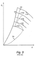
- the minimum operating speed is defined by the compressor manufacturer. It is generally depicted as the lowest performance curve in a compressor performance map such as shown in Figs. 2 and 3 . Lower speeds, greater than idle speed, are experienced on startup and shutdown, but the compressor is not operated continuously at these speeds.
- the minimum operating speed is simply the constant operating rotational speed.
- the accepted startup procedure for a turbocompressor is to increase the rotational speed of the compressor with the antisurge valve 120 wide open until the compressor reaches the compressor's minimum operating speed (if the compressor is operated at variable speed) or the compressor's operating speed (if the compressor is operated at variable speed) or the compressor's operating speed (if the compressor is driven by a constant speed driver).
- the antisurge valve 120 is ramped closed and the compressor's 100 automatic performance control takes control of the compressor's rotational speed, inlet throttling valve 130, or variable guide vanes to control the compressor's 100 capacity.
- the compressor's 100 operating point trajectory 320 is shown as a dot-dashed line. Curves of constant compressor rotational speed 310a-310e are shown as solid lines. The curve 310a represents the minimum operating rotational speed, while the curve 310e represents the maximum operating rotational speed. Because the recycle valve 120 is maintained in its fully open position until minimum rotational speed has been achieved, the compressor operating point trajectory 320 tends to give wide berth to the surge limit curve 210 in the region below the minimum rotational speed curve 310a.
- the surge limit curve 210 is usually unknown for rotational speeds less than the minimum operating speed, and that pressure and flow sensor signals of reasonable magnitude must be achieved before a valid compressor operating point may be determined.
- the compressor's operating point must be calculated to compare its location to the surge limit line 210, or surge control line 220 to avoid having the compressor's operating point cross the surge limit line 210.
- Antisurge control algorithms are described in the Compressor Controls Series 5 Antisurge Control Application Manual, Publication UM5411 rev. 2.8.0 December 2007.
- a gas turbine driver may experience high exhaust gas temperatures during the startup of a turbocompressor.
- An electric motor driver may trip on thermal overload due to a current being too high for too long a duration.
- An object of the present invention is to provide a method and apparatus for safely starting a turbocompressor while minimizing an overall energy required to accomplish the startup.
- EP-A-1 041 290 discloses a method and apparatus having the pre-characterising features of claims 1 and 9.
- Compressors having gas turbine drivers and variable frequency drive electric motors tend to have long startup times - on the order of several minutes.
- a first embodiment of this invention prescribes that the compressor's antisurge valve be maintained at its fully open position until predetermined signal strengths are realized from the compressor's suction and discharge pressure sensors, and the flow sensor. At this point, the antisurge valve is ramped closed at a predetermined rate under control of the antisurge control system to keep the compressor's operating point from crossing the surge control curve. Startup continues independently of the antisurge controller's operation.
- a second class of compressors comprises constant-speed electric motor driven compressors.
- the startup times for this class of compressors tend to be on the order of less than a minute.
- the control system starts the antisurge valve in a fully open position, and begins to ramp the antisurge valve closed at a predetermined rate after a predetermined time has elapsed after the initiation of the startup of the compressor. Because of the rapid startup, the pressure and flow sensor signals become viable very quickly, so antisurge control may be carried out before the compressor's operating point reaches the surge control curve.
- FIG. 4 A typical compressor performance map in H p -Q coordinates is shown in Fig. 4 .
- H p is polytropic head and Q is volumetric flow rate - usually in the suction.
- the map of Fig. 4 comprises solid-line curves of constant rotational speed 310a-310e and dashed-line curves of constant shaft power 410a-410e.
- the required shaft power decreases as the operating point moves toward the surge limit 210.
- an operating point trajectory 520 shown in Fig.
- the short-dashed curve 510 represents a surge control line - a line set a predetermined distance from the surge limit line 210 toward the stable operating region, thus providing a safety margin for the antisurge control system.
- limit control is applied to the compressor 100 to maintain the operating point at or to the right of the surge control line 510.
- an antisurge or recycle valve 120 is manipulated to maintain an adequate flow rate through the compressor 100 .
- the manipulation of the antisurge valve 120 is carried out via an automatic control algorithm in the antisurge controller, A/S PID 610, of Figs. 6a, 6b, and 7 .
- Typical inputs to the antisurge controller 610 are shown in Figs.
- the antisurge valve 120 is initially fully open, but is ramped closed by the control system as soon as safe operation may be assured.
- One embodiment of the instant invention is depicted in the flow diagram of Fig. 8 . This embodiment is particularly useful when the startup process is "slow," taking on the order of several minutes from its initiation.
- the antisurge valve 120 is set initially at its full open position as shown in block 800. The full open position may vary between valve types. Generally, full open in the context of this invention is the greatest opening the antisurge valve 120 will realize in its duty in the specific application. The present invention does not depend on the percent opening value at which the antisurge valve 120 is considered in its full open position.
- the control system 610 repeatedly checks the signals received from the flow transmitter 620, suction pressure transmitter 630, and discharge pressure transmitter 635.
- the signal values are compared to threshold values, ⁇ p o,min , p s,min , and p d,min , respectively in comparator blocks 815, 820, 825. If the signal magnitude of one or more of the input signals, ⁇ p o , p s , and p d , is not at least as great as its respective threshold value, the rotational speed of the compressor 100 continues to be ramped up as indicated in block 810.
- ⁇ p o,min , p s,min , and p d,min exceed their threshold values ⁇ p o,min , p s,min , and p d,min .
- the antisurge controller 610 compares the compressor's operating point to the surge control line 510 to determine how the antisurge valve 120 must be manipulated for antisurge protection.
- the antisurge valve 120 is ramped toward its closed position according to a predetermined schedule as shown in block 850. If the operating point is on or to the left of the surge control line 510, the antisurge controller 610 manipulates the antisurge valve's 120 position to keep the compressor 100 safe from surge as shown in block 845.
- the other essentially simultaneous operation involves continuing to increase the compressor's rotational speed according to block 855 until the minimum operating speed, N min , or some predetermined value of speed is reached.
- the rotational speed set point used by the VFD controller 650 or the speed controller 720 is increased with time.
- the comparator block 840 determines the compressor 100 has reached its minimum operating speed, the control system is shifted from its startup mode to its RUN mode, as shown in block 860. At that point, the capacity or performance control system takes over varying the compressor speed according to the needs of the process.
- the minimum operating speed, N min in comparator block 840 may be the compressor's operating speed if the compressor 120 is to be operated at a constant speed.
- FIG. 9 An additional embodiment is shown in Fig. 9 . This embodiment is particularly useful for compressors 120 that may be started rapidly - in less than a minute, for instance.
- the antisurge valve 120 is set initially at its full open position as shown in block 800.
- a timer is reset to zero.
- startup can be initiated as shown in block 805.
- the rotational speed of the compressor 100 is ramped up according to the guidelines and restrictions of the compressor 100 and driver 110, 710 manufacturers and the needs of the equipment owner. Speed rampup is carried out by increasing the VFD controller's 650 or rotational speed controller's 720 set point, and is depicted in block 810.
- the antisurge valve is ramped toward a closed position after a predetermined time elapses.
- the time as reported by the timer is compared to the time threshold, t PD . If the time does not exceed the threshold time, the speed continues to increase, but no change to the position of the antisurge valve 120 is made.
- the threshold time, t PD has elapsed, two operations are carried out essentially simultaneously and repeatedly. Each of these operations emanates from and returns to the branch block 830. In one of these operations, the antisurge controller 610 compares the compressor's operating point to the surge control line 510 to determine how the antisurge valve 120 must be manipulated for antisurge protection.
- the antisurge valve 120 is ramped toward its closed position according to a predetermined ramp rate as shown in block 850. If the operating point is on or to the left of the surge control line 510, the antisurge controller 610 manipulates the antisurge valve's 120 position to keep the compressor 100 safe from surge as shown in block 845.
- the other essentially simultaneous operation involves continuing to increase the compressor's rotational speed according to block 855 until the minimum operating speed, N min , or some predetermined value of speed is reached.
- the control system is shifted from its startup mode to its RUN mode, as shown in block 860. At that point, the capacity or performance control system takes over varying the compressor speed according to the needs of the process.
- the minimum operating speed, N min in comparator block 840 may be the compressor's operating speed if the compressor 120 is to be operated at a constant speed.
- a third embodiment is illustrated, differing from the embodiment of Fig. 9 in that the driver of Fig. 10 is a constant speed driver, such as a constant speed electric motor 645 ( Fig. 6b ).
- the process of accelerating the driver up to its operating speed, N op does not incorporate a decision to continue accelerating the driver inasmuch as the driver will continue to accelerate until its operating speed, N op , is reached or it is tripped. Therefore, block 1055 indicates only that the rotational speed continues to rise.
- Block 1040 is intended only to indicate the compressor rotational speed will increase until the operating speed, N op , is reached, and not that a decision is being made in this comparator block.
- the control system reverts to a RUN mode 860 wherein performance or capacity control is carried out to satisfy process constraints.
- the predetermined time lapse, t PD in comparator block 920 may be zero so the antisurge valve 120 begins to close immediately as startup begins.
- the last two embodiments differ from the prior art in that, in the instant invention, time is used to determine when the antisurge valve 120 is ramped toward its closed position, rather than rotational speed.
- Figs. 8 , 9 and 10 may be considered contents of a logic unit within a compressor control system, such as the antisurge controller 610 depicted in Figs. 6a, 6b, and 7 .
- FIG. 11 More detail of the startup initiation block 810 is shown in Fig. 11 .
- a check to ascertain the antisurge valve 120 is fully open is first carried out in query block 1110. If the antisurge valve 120 is not fully open, the flow moves to a valve open function 1120. Once the antisurge valve 120 is fully open, the turbocompressor rotational speed is increased from an initial, zero value as shown in block 1130.
Landscapes
- Engineering & Computer Science (AREA)
- Mechanical Engineering (AREA)
- General Engineering & Computer Science (AREA)
- Control Of Positive-Displacement Air Blowers (AREA)
- Supercharger (AREA)
Claims (14)
- Procédé pour réduire au minimum une énergie requise pour faire démarrer un turbocompresseur (100, 110 ; 100, 710 ; 100, 645) ayant une vanne anti-pompage (120) et un système de commande (610), ce procédé comprenant :(a) l'ouverture à fond de la vanne anti-pompage ;(b) le déclenchement d'un démarrage du turbocompresseur ; et(c) l'augmentation d'une vitesse de rotation du turbocompresseur à partir d'une vitesse de rotation nulle, caractérisé en ce que ce procédé comprend l'étape consistant à :(d) actionner la vanne anti-pompage vers sa position fermée avant que ledit turbocompresseur n'atteigne une vitesse de rotation de fonctionnement minimum.
- Procédé selon la revendication 1, dans lequel un déclenchement d'une fermeture de la vanne anti-pompage (120) comprend :(a) la détection d'au moins un signal par le système de commande (610) ;(b) la comparaison d'une grandeur du au moins un signal avec une valeur seuil minimum ; et(c) le déclenchement de la fermeture de la vanne anti-pompage lorsque la grandeur du au moins un signal dépasse la valeur seuil minimum.
- Procédé selon la revendication 1, dans lequel un déclenchement d'une fermeture de la vanne anti-pompage (120) comprend :(a) l'initialisation d'un chronomètre à une valeur initiale à un moment de déclenchement du démarrage du turbocompresseur (100, 710) ;(b) la mesure du temps écoulé depuis la valeur initiale ;(c) la comparaison du temps écoulé avec une valeur seuil ; et(d) le déclenchement de la fermeture de la vanne anti-pompage lorsque le temps écoulé dépasse la valeur seuil.
- Procédé selon la revendication 3, dans lequel la vitesse de rotation de fonctionnement minimum comprend une vitesse de rotation de fonctionnement constante du turbocompresseur, ce procédé comprenant en outre :(a) le fait de permettre à un organe d'entraînement (645) du turbocompresseur (100, 645) d'atteindre la vitesse de rotation de fonctionnement constante ; et(b) le fait de faire marcher le turbocompresseur à la vitesse de fonctionnement constante.
- Procédé selon la revendication 1, dans lequel l'augmentation d'une vitesse de rotation du turbocompresseur (100, 710) à partir d'une vitesse de rotation nulle comprend :(a) l'augmentation d'une valeur de consigne de vitesse de rotation du turbocompresseur au sein du système de commande (610) ; et(b) le contrôle de la vitesse de rotation du turbocompresseur en se basant sur ladite valeur de consigne de vitesse de rotation du turbocompresseur.
- Procédé selon la revendication 3, dans lequel la valeur de seuil est égale à la valeur initiale.
- Procédé selon la revendication 1, dans lequel un déclenchement d'une fermeture de la vanne anti-pompage (120) comprend :(a) la détection d'une pluralité de signaux envoyés au système de commande (610) ;(b) la comparaison des grandeurs de chacun de ladite pluralité de signaux avec une valeur seuil minimum respective ; et(c) le déclenchement de la fermeture de la vanne anti-pompage lorsque les grandeurs de la pluralité de signaux dépassent les valeurs seuils minimum respectives.
- Procédé selon la revendication 1, dans lequel l'actionnement de la vanne anti-pompage (120) vers sa position fermée avant que ledit turbocompresseur (100, 170) n'atteigne une vitesse de rotation de fonctionnement minimum comprend :(a) la détection d'un signal indiquant un point de fonctionnement du turbocompresseur ;(b) la comparaison dudit signal avec une valeur représentant une ligne de régulation de pompage ; et(c) la manipulation de la vanne anti-pompage pour empêcher le point de fonctionnement du turbocompresseur de résider plus près d'une région de pompage que la ligne de régulation de pompage.
- Appareil pour réduire au minimum une énergie requise pour faire démarrer un turbocompresseur (100, 110 ; 100, 710 ; 100, 645), cet appareil comprenant :(a) une vanne anti-pompage (120) ;(b) un système de commande (610) ;(c) une première fonction du système de commande pour générer un premier signal pour ouvrir à fond la vanne anti-pompage ;(d) une deuxième fonction du système de commande pour déclencher un démarrage du turbocompresseur et augmenter une valeur de consigne de vitesse de rotation du turbocompresseur à partir d'une valeur de consigne de vitesse de rotation nulle, cet appareil étant caractérisé en ce qu'il comprend :(e) une troisième fonction du système de commande pour discerner que les conditions sont appropriées pour déclencher une fermeture de la vanne anti-pompage avant que ledit turbocompresseur n'atteigne une vitesse de rotation de fonctionnement minimum ; et(f) une quatrième fonction du système de commande pour générer un deuxième signal afin d'actionner la vanne anti-pompage vers sa position fermée après que la troisième fonction du système de commande a discerné que les conditions sont appropriées pour déclencher la fermeture de la vanne anti-pompage.
- Appareil selon la revendication 9, comprenant en outre :(a) au moins un signal généré par un système de mesure et détecté par le système de commande (610) ;(b) un comparateur dans le système de commande pour comparer une grandeur du au moins un signal avec une valeur seuil minimum ; et(c) une fonction de génération de signal d'actionnement d'anti-pompage au sein du système de commande pour déclencher une fermeture de la vanne anti-pompage (120) lorsque la grandeur du au moins un signal dépasse la valeur seuil minimum.
- Appareil selon la revendication 9, comprenant en outre :(a) un chronomètre, utilisé pour mesurer un temps écoulé à partir d'un déclenchement du démarrage du turbocompresseur (100, 710) ;(b) un comparateur dans le système de commande (610) pour comparer le temps écoulé avec une valeur seuil ; et(c) une fonction de génération de signal d'actionnement d'anti-pompage au sein du système de commande pour déclencher une fermeture de la vanne anti-pompage (120) lorsque le temps écoulé dépasse la valeur seuil.
- Appareil selon la revendication 9, dans lequel la deuxième fonction du système de commande comprend :(a) une fonction de génération de valeur de consigne de vitesse de rotation au sein du système de commande (610) ; et(b) un système de commande en boucle fermée pour contrôler la vitesse de rotation du turbocompresseur en se basant sur ladite valeur de consigne de vitesse de rotation du turbocompresseur.
- Appareil selon la revendication 9, comprenant en outre :(a) une pluralité de signaux générés par un système de mesure et détectés par le système de commande (610) ;(b) un comparateur dans le système de commande pour comparer une grandeur de chacun de la pluralité de signaux avec une valeur seuil minimum respective ; et(c) une fonction de génération de signal d'actionnement d'anti-pompage au sein du système de commande pour déclencher une fermeture de la vanne anti-pompage (120) lorsque la grandeur de la totalité de la pluralité de signaux dépasse les valeurs seuils minimum respectives.
- Appareil selon la revendication 9, dans lequel la quatrième fonction du système de commande comprend en outre :(a) un signal indiquant un point de fonctionnement du turbocompresseur ;(b) une fonction de comparaison pour comparer ledit signal avec une valeur représentant une ligne de régulation de pompage ; et(c) un système de commande en boucle fermée pour manipuler la vanne anti-pompage (120) afin d'empêcher le point de fonctionnement du turbocompresseur de résider plus près d'une région de pompage que la ligne de régulation de pompage.
Applications Claiming Priority (1)
| Application Number | Priority Date | Filing Date | Title |
|---|---|---|---|
| US12/128,265 US20090297333A1 (en) | 2008-05-28 | 2008-05-28 | Enhanced Turbocompressor Startup |
Publications (2)
| Publication Number | Publication Date |
|---|---|
| EP2128449A1 EP2128449A1 (fr) | 2009-12-02 |
| EP2128449B1 true EP2128449B1 (fr) | 2011-04-13 |
Family
ID=40996634
Family Applications (1)
| Application Number | Title | Priority Date | Filing Date |
|---|---|---|---|
| EP09160230A Active EP2128449B1 (fr) | 2008-05-28 | 2009-05-14 | Démarrage de turbocompresseur amélioré |
Country Status (4)
| Country | Link |
|---|---|
| US (3) | US20090297333A1 (fr) |
| EP (1) | EP2128449B1 (fr) |
| AT (1) | ATE505650T1 (fr) |
| DE (1) | DE602009001048D1 (fr) |
Families Citing this family (21)
| Publication number | Priority date | Publication date | Assignee | Title |
|---|---|---|---|---|
| US8079227B2 (en) * | 2005-12-29 | 2011-12-20 | Johnson Controls Technology Company | Reduced compressor capacity controls |
| US20090297333A1 (en) * | 2008-05-28 | 2009-12-03 | Saul Mirsky | Enhanced Turbocompressor Startup |
| CN104533767B (zh) * | 2014-12-26 | 2018-02-16 | 沈阳鼓风机集团自动控制系统工程有限公司 | 压缩机启动控制方法 |
| CN104500378A (zh) * | 2014-12-26 | 2015-04-08 | 沈阳鼓风机集团自动控制系统工程有限公司 | 压缩机启动控制装置 |
| US9828887B2 (en) | 2015-03-19 | 2017-11-28 | General Electric Company | Power generation system having compressor creating excess air flow and turbo-expander to increase turbine exhaust gas mass flow |
| US9863284B2 (en) | 2015-03-19 | 2018-01-09 | General Electric Company | Power generation system having compressor creating excess air flow and cooling fluid injection therefor |
| US20160273397A1 (en) * | 2015-03-19 | 2016-09-22 | General Electric Company | Power generation system having compressor creating excess air flow and supplemental compressor therefor |
| US9822670B2 (en) | 2015-03-19 | 2017-11-21 | General Electric Company | Power generation system having compressor creating excess air flow and turbo-expander for cooling inlet air |
| US20170102829A1 (en) * | 2015-10-08 | 2017-04-13 | Funai Electric Co., Ltd. | Input device |
| CN105465029B (zh) * | 2016-01-11 | 2017-06-27 | 北京北排水环境发展有限公司 | 一种基于工频电机的鼓风机变频控制装置及其控制方法 |
| US10110156B2 (en) * | 2016-02-01 | 2018-10-23 | Hamilton Sunstrand Corporation | Reducing fault energy from an electric motor drive for a compressor |
| IT201600077686A1 (it) * | 2016-07-26 | 2018-01-26 | Turboden Spa | Metodo di controllo di un compressore meccanicamente accoppiato ad una turbina |
| CN106640725A (zh) * | 2016-11-14 | 2017-05-10 | 北京化工大学 | 一种离心压缩机喘振故障调控方法 |
| US11788466B2 (en) * | 2017-12-08 | 2023-10-17 | Schlumberger Technology Corporation | Compressed N2 for energy storage |
| IT201900005554A1 (it) * | 2019-04-10 | 2020-10-10 | Nuovo Pignone Tecnologie Srl | Sistema di compressione e metodo per il controllo di un sistema di compressione |
| EP3819261A1 (fr) * | 2019-11-08 | 2021-05-12 | Casale Sa | Contrôle d'une boucle de synthèse d'ammoniac à charge partielle |
| WO2022089820A1 (fr) * | 2020-10-30 | 2022-05-05 | Casale Sa | Contrôle d'une boucle de synthèse d'ammoniac à charge partielle |
| JP7474685B2 (ja) * | 2020-11-27 | 2024-04-25 | 三菱重工業株式会社 | 制御装置、制御方法およびプログラム |
| US12320445B2 (en) * | 2023-01-30 | 2025-06-03 | The Boeing Company | System, method, and valve assembly for surge protection |
| CN117053445A (zh) * | 2023-08-25 | 2023-11-14 | 深圳市英维克科技股份有限公司 | 压缩机的防喘振控制方法及空调器 |
| US20250216036A1 (en) * | 2023-12-28 | 2025-07-03 | Saudi Arabian Oil Company | Startup control system and method for centrifugal compressors |
Family Cites Families (17)
| Publication number | Priority date | Publication date | Assignee | Title |
|---|---|---|---|---|
| US4164035A (en) * | 1977-09-14 | 1979-08-07 | Sundstrand Corporation | Surge control for variable speed-variable geometry compressors |
| US4281970A (en) | 1979-06-15 | 1981-08-04 | Phillips Petroleum Company | Turbo-expander control |
| FR2666854B1 (fr) | 1990-09-19 | 1992-12-18 | Framatome Sa | Dispositif de commande de moyens d'antipompage d'un compresseur. |
| US5306116A (en) * | 1992-04-10 | 1994-04-26 | Ingersoll-Rand Company | Surge control and recovery for a centrifugal compressor |
| US5743715A (en) | 1995-10-20 | 1998-04-28 | Compressor Controls Corporation | Method and apparatus for load balancing among multiple compressors |
| US5967742A (en) | 1997-12-23 | 1999-10-19 | Compressor Controls Corporation | Method and apparatus for preventing surge while taking a turbocompressor off-line from a parallel configuration |
| US6217288B1 (en) | 1998-01-20 | 2001-04-17 | Compressor Controls Corporation | Method and apparatus for limiting a critical variable of a group of compressors or an individual compressor |
| US6332336B1 (en) | 1999-02-26 | 2001-12-25 | Compressor Controls Corporation | Method and apparatus for maximizing the productivity of a natural gas liquids production plant |
| JP4115037B2 (ja) * | 1999-04-02 | 2008-07-09 | 三菱重工業株式会社 | ガスタービン起動方法 |
| US6308531B1 (en) | 1999-10-12 | 2001-10-30 | Air Products And Chemicals, Inc. | Hybrid cycle for the production of liquefied natural gas |
| GB2376515B (en) * | 2001-06-13 | 2004-09-29 | Rolls Royce Plc | Bleed valve assembly |
| US7356999B2 (en) | 2003-10-10 | 2008-04-15 | York International Corporation | System and method for stability control in a centrifugal compressor |
| US7096669B2 (en) * | 2004-01-13 | 2006-08-29 | Compressor Controls Corp. | Method and apparatus for the prevention of critical process variable excursions in one or more turbomachines |
| US7555905B2 (en) * | 2006-03-28 | 2009-07-07 | United Technologies Corporation | Self-actuating bleed valve for gas turbine engine |
| US7972105B2 (en) * | 2007-05-10 | 2011-07-05 | General Electric Company | Turbine anti-rotating stall schedule |
| US8360744B2 (en) * | 2008-03-13 | 2013-01-29 | Compressor Controls Corporation | Compressor-expander set critical speed avoidance |
| US20090297333A1 (en) * | 2008-05-28 | 2009-12-03 | Saul Mirsky | Enhanced Turbocompressor Startup |
-
2008
- 2008-05-28 US US12/128,265 patent/US20090297333A1/en not_active Abandoned
-
2009
- 2009-05-14 EP EP09160230A patent/EP2128449B1/fr active Active
- 2009-05-14 DE DE602009001048T patent/DE602009001048D1/de active Active
- 2009-05-14 AT AT09160230T patent/ATE505650T1/de not_active IP Right Cessation
-
2013
- 2013-09-18 US US14/030,035 patent/US9879688B2/en active Active
-
2018
- 2018-01-26 US US15/880,820 patent/US10935036B2/en active Active
Also Published As
| Publication number | Publication date |
|---|---|
| US20180149163A1 (en) | 2018-05-31 |
| US10935036B2 (en) | 2021-03-02 |
| EP2128449A1 (fr) | 2009-12-02 |
| US20090297333A1 (en) | 2009-12-03 |
| ATE505650T1 (de) | 2011-04-15 |
| DE602009001048D1 (de) | 2011-05-26 |
| US20140030058A1 (en) | 2014-01-30 |
| US9879688B2 (en) | 2018-01-30 |
Similar Documents
| Publication | Publication Date | Title |
|---|---|---|
| EP2128449B1 (fr) | Démarrage de turbocompresseur amélioré | |
| EP2215365B1 (fr) | Système de commande | |
| US9086070B2 (en) | Compressors control | |
| AU2007347705B2 (en) | Anti-bogdown control system for turbine/compressor systems | |
| CN102449283B (zh) | 电动增压器 | |
| US20090317260A1 (en) | Compressor-Driver Power Limiting in Consideration of Antisurge Control | |
| US9989068B2 (en) | Method for controlling a trim-adjustment mechanism for a centrifugal compressor | |
| EP2042743A1 (fr) | Système de compression de gaz, procédé pour le contrôle d'un système de compression de gaz et dispositif pour le contrôle d'une vanne de recyclage | |
| AU2008292008B2 (en) | Improvements in compressor control | |
| JP4345672B2 (ja) | ターボ圧縮機およびその運転方法 | |
| EP3543538B1 (fr) | Procédé de commande d'un mécanisme de réglage de compensation d'un compresseur centrifuge | |
| US20040247452A1 (en) | Method of controlling a plurality of compressors | |
| CN116670380A (zh) | 控制包括电机的涡轮机的方法 | |
| JP3703872B2 (ja) | ガスタービン | |
| JP2977406B2 (ja) | 圧縮機の制御装置 | |
| KR20050012562A (ko) | 고로 송풍기의 기계적 충격 방지를 위한 제어방법 | |
| JP2006316759A (ja) | 圧縮装置 | |
| JP2003322097A (ja) | 流体機械の流量制御方法 | |
| JPH0240886B2 (fr) | ||
| JP2010216330A (ja) | ターボチャージャーの可変ノズル制御装置 |
Legal Events
| Date | Code | Title | Description |
|---|---|---|---|
| PUAI | Public reference made under article 153(3) epc to a published international application that has entered the european phase |
Free format text: ORIGINAL CODE: 0009012 |
|
| AK | Designated contracting states |
Kind code of ref document: A1 Designated state(s): AT BE BG CH CY CZ DE DK EE ES FI FR GB GR HR HU IE IS IT LI LT LU LV MC MK MT NL NO PL PT RO SE SI SK TR |
|
| 17P | Request for examination filed |
Effective date: 20091211 |
|
| 17Q | First examination report despatched |
Effective date: 20100112 |
|
| GRAP | Despatch of communication of intention to grant a patent |
Free format text: ORIGINAL CODE: EPIDOSNIGR1 |
|
| GRAS | Grant fee paid |
Free format text: ORIGINAL CODE: EPIDOSNIGR3 |
|
| GRAA | (expected) grant |
Free format text: ORIGINAL CODE: 0009210 |
|
| AK | Designated contracting states |
Kind code of ref document: B1 Designated state(s): AT BE BG CH CY CZ DE DK EE ES FI FR GB GR HR HU IE IS IT LI LT LU LV MC MK MT NL NO PL PT RO SE SI SK TR |
|
| REG | Reference to a national code |
Ref country code: GB Ref legal event code: FG4D |
|
| REG | Reference to a national code |
Ref country code: CH Ref legal event code: EP |
|
| REG | Reference to a national code |
Ref country code: IE Ref legal event code: FG4D |
|
| REF | Corresponds to: |
Ref document number: 602009001048 Country of ref document: DE Date of ref document: 20110526 Kind code of ref document: P |
|
| REG | Reference to a national code |
Ref country code: DE Ref legal event code: R096 Ref document number: 602009001048 Country of ref document: DE Effective date: 20110526 |
|
| REG | Reference to a national code |
Ref country code: NL Ref legal event code: T3 |
|
| LTIE | Lt: invalidation of european patent or patent extension |
Effective date: 20110413 |
|
| PG25 | Lapsed in a contracting state [announced via postgrant information from national office to epo] |
Ref country code: PT Free format text: LAPSE BECAUSE OF FAILURE TO SUBMIT A TRANSLATION OF THE DESCRIPTION OR TO PAY THE FEE WITHIN THE PRESCRIBED TIME-LIMIT Effective date: 20110816 Ref country code: NO Free format text: LAPSE BECAUSE OF FAILURE TO SUBMIT A TRANSLATION OF THE DESCRIPTION OR TO PAY THE FEE WITHIN THE PRESCRIBED TIME-LIMIT Effective date: 20110713 Ref country code: LT Free format text: LAPSE BECAUSE OF FAILURE TO SUBMIT A TRANSLATION OF THE DESCRIPTION OR TO PAY THE FEE WITHIN THE PRESCRIBED TIME-LIMIT Effective date: 20110413 Ref country code: SE Free format text: LAPSE BECAUSE OF FAILURE TO SUBMIT A TRANSLATION OF THE DESCRIPTION OR TO PAY THE FEE WITHIN THE PRESCRIBED TIME-LIMIT Effective date: 20110413 Ref country code: HR Free format text: LAPSE BECAUSE OF FAILURE TO SUBMIT A TRANSLATION OF THE DESCRIPTION OR TO PAY THE FEE WITHIN THE PRESCRIBED TIME-LIMIT Effective date: 20110413 |
|
| PG25 | Lapsed in a contracting state [announced via postgrant information from national office to epo] |
Ref country code: BE Free format text: LAPSE BECAUSE OF FAILURE TO SUBMIT A TRANSLATION OF THE DESCRIPTION OR TO PAY THE FEE WITHIN THE PRESCRIBED TIME-LIMIT Effective date: 20110413 Ref country code: CY Free format text: LAPSE BECAUSE OF FAILURE TO SUBMIT A TRANSLATION OF THE DESCRIPTION OR TO PAY THE FEE WITHIN THE PRESCRIBED TIME-LIMIT Effective date: 20110413 Ref country code: ES Free format text: LAPSE BECAUSE OF FAILURE TO SUBMIT A TRANSLATION OF THE DESCRIPTION OR TO PAY THE FEE WITHIN THE PRESCRIBED TIME-LIMIT Effective date: 20110724 Ref country code: FI Free format text: LAPSE BECAUSE OF FAILURE TO SUBMIT A TRANSLATION OF THE DESCRIPTION OR TO PAY THE FEE WITHIN THE PRESCRIBED TIME-LIMIT Effective date: 20110413 Ref country code: AT Free format text: LAPSE BECAUSE OF FAILURE TO SUBMIT A TRANSLATION OF THE DESCRIPTION OR TO PAY THE FEE WITHIN THE PRESCRIBED TIME-LIMIT Effective date: 20110413 Ref country code: IS Free format text: LAPSE BECAUSE OF FAILURE TO SUBMIT A TRANSLATION OF THE DESCRIPTION OR TO PAY THE FEE WITHIN THE PRESCRIBED TIME-LIMIT Effective date: 20110813 Ref country code: GR Free format text: LAPSE BECAUSE OF FAILURE TO SUBMIT A TRANSLATION OF THE DESCRIPTION OR TO PAY THE FEE WITHIN THE PRESCRIBED TIME-LIMIT Effective date: 20110714 Ref country code: LV Free format text: LAPSE BECAUSE OF FAILURE TO SUBMIT A TRANSLATION OF THE DESCRIPTION OR TO PAY THE FEE WITHIN THE PRESCRIBED TIME-LIMIT Effective date: 20110413 Ref country code: SI Free format text: LAPSE BECAUSE OF FAILURE TO SUBMIT A TRANSLATION OF THE DESCRIPTION OR TO PAY THE FEE WITHIN THE PRESCRIBED TIME-LIMIT Effective date: 20110413 |
|
| PG25 | Lapsed in a contracting state [announced via postgrant information from national office to epo] |
Ref country code: MC Free format text: LAPSE BECAUSE OF NON-PAYMENT OF DUE FEES Effective date: 20110531 Ref country code: MT Free format text: LAPSE BECAUSE OF FAILURE TO SUBMIT A TRANSLATION OF THE DESCRIPTION OR TO PAY THE FEE WITHIN THE PRESCRIBED TIME-LIMIT Effective date: 20110413 |
|
| PG25 | Lapsed in a contracting state [announced via postgrant information from national office to epo] |
Ref country code: CZ Free format text: LAPSE BECAUSE OF FAILURE TO SUBMIT A TRANSLATION OF THE DESCRIPTION OR TO PAY THE FEE WITHIN THE PRESCRIBED TIME-LIMIT Effective date: 20110413 Ref country code: EE Free format text: LAPSE BECAUSE OF FAILURE TO SUBMIT A TRANSLATION OF THE DESCRIPTION OR TO PAY THE FEE WITHIN THE PRESCRIBED TIME-LIMIT Effective date: 20110413 |
|
| PLBE | No opposition filed within time limit |
Free format text: ORIGINAL CODE: 0009261 |
|
| STAA | Information on the status of an ep patent application or granted ep patent |
Free format text: STATUS: NO OPPOSITION FILED WITHIN TIME LIMIT |
|
| PG25 | Lapsed in a contracting state [announced via postgrant information from national office to epo] |
Ref country code: PL Free format text: LAPSE BECAUSE OF FAILURE TO SUBMIT A TRANSLATION OF THE DESCRIPTION OR TO PAY THE FEE WITHIN THE PRESCRIBED TIME-LIMIT Effective date: 20110413 Ref country code: SK Free format text: LAPSE BECAUSE OF FAILURE TO SUBMIT A TRANSLATION OF THE DESCRIPTION OR TO PAY THE FEE WITHIN THE PRESCRIBED TIME-LIMIT Effective date: 20110413 |
|
| REG | Reference to a national code |
Ref country code: IE Ref legal event code: MM4A |
|
| REG | Reference to a national code |
Ref country code: FR Ref legal event code: ST Effective date: 20120210 |
|
| 26N | No opposition filed |
Effective date: 20120116 |
|
| PG25 | Lapsed in a contracting state [announced via postgrant information from national office to epo] |
Ref country code: IE Free format text: LAPSE BECAUSE OF NON-PAYMENT OF DUE FEES Effective date: 20110514 Ref country code: FR Free format text: LAPSE BECAUSE OF NON-PAYMENT OF DUE FEES Effective date: 20110614 |
|
| REG | Reference to a national code |
Ref country code: DE Ref legal event code: R097 Ref document number: 602009001048 Country of ref document: DE Effective date: 20120116 |
|
| PG25 | Lapsed in a contracting state [announced via postgrant information from national office to epo] |
Ref country code: IT Free format text: LAPSE BECAUSE OF FAILURE TO SUBMIT A TRANSLATION OF THE DESCRIPTION OR TO PAY THE FEE WITHIN THE PRESCRIBED TIME-LIMIT Effective date: 20110413 |
|
| PG25 | Lapsed in a contracting state [announced via postgrant information from national office to epo] |
Ref country code: MK Free format text: LAPSE BECAUSE OF FAILURE TO SUBMIT A TRANSLATION OF THE DESCRIPTION OR TO PAY THE FEE WITHIN THE PRESCRIBED TIME-LIMIT Effective date: 20110413 |
|
| PG25 | Lapsed in a contracting state [announced via postgrant information from national office to epo] |
Ref country code: LU Free format text: LAPSE BECAUSE OF NON-PAYMENT OF DUE FEES Effective date: 20110514 |
|
| PG25 | Lapsed in a contracting state [announced via postgrant information from national office to epo] |
Ref country code: BG Free format text: LAPSE BECAUSE OF FAILURE TO SUBMIT A TRANSLATION OF THE DESCRIPTION OR TO PAY THE FEE WITHIN THE PRESCRIBED TIME-LIMIT Effective date: 20110713 |
|
| PG25 | Lapsed in a contracting state [announced via postgrant information from national office to epo] |
Ref country code: TR Free format text: LAPSE BECAUSE OF FAILURE TO SUBMIT A TRANSLATION OF THE DESCRIPTION OR TO PAY THE FEE WITHIN THE PRESCRIBED TIME-LIMIT Effective date: 20110413 |
|
| PG25 | Lapsed in a contracting state [announced via postgrant information from national office to epo] |
Ref country code: HU Free format text: LAPSE BECAUSE OF FAILURE TO SUBMIT A TRANSLATION OF THE DESCRIPTION OR TO PAY THE FEE WITHIN THE PRESCRIBED TIME-LIMIT Effective date: 20110413 |
|
| REG | Reference to a national code |
Ref country code: CH Ref legal event code: PL |
|
| PG25 | Lapsed in a contracting state [announced via postgrant information from national office to epo] |
Ref country code: CH Free format text: LAPSE BECAUSE OF NON-PAYMENT OF DUE FEES Effective date: 20130531 Ref country code: LI Free format text: LAPSE BECAUSE OF NON-PAYMENT OF DUE FEES Effective date: 20130531 |
|
| PGFP | Annual fee paid to national office [announced via postgrant information from national office to epo] |
Ref country code: GB Payment date: 20140404 Year of fee payment: 6 |
|
| GBPC | Gb: european patent ceased through non-payment of renewal fee |
Effective date: 20150514 |
|
| PG25 | Lapsed in a contracting state [announced via postgrant information from national office to epo] |
Ref country code: GB Free format text: LAPSE BECAUSE OF NON-PAYMENT OF DUE FEES Effective date: 20150514 |
|
| P01 | Opt-out of the competence of the unified patent court (upc) registered |
Effective date: 20230527 |
|
| PGFP | Annual fee paid to national office [announced via postgrant information from national office to epo] |
Ref country code: NL Payment date: 20250526 Year of fee payment: 17 |
|
| PGFP | Annual fee paid to national office [announced via postgrant information from national office to epo] |
Ref country code: DE Payment date: 20250528 Year of fee payment: 17 |