EP2128451A1 - Ventilateur sirocco et conditionneur d'air - Google Patents
Ventilateur sirocco et conditionneur d'air Download PDFInfo
- Publication number
- EP2128451A1 EP2128451A1 EP08722743A EP08722743A EP2128451A1 EP 2128451 A1 EP2128451 A1 EP 2128451A1 EP 08722743 A EP08722743 A EP 08722743A EP 08722743 A EP08722743 A EP 08722743A EP 2128451 A1 EP2128451 A1 EP 2128451A1
- Authority
- EP
- European Patent Office
- Prior art keywords
- scroll
- fan
- motor
- straight line
- air
- Prior art date
- Legal status (The legal status is an assumption and is not a legal conclusion. Google has not performed a legal analysis and makes no representation as to the accuracy of the status listed.)
- Granted
Links
Images




Classifications
-
- F—MECHANICAL ENGINEERING; LIGHTING; HEATING; WEAPONS; BLASTING
- F04—POSITIVE - DISPLACEMENT MACHINES FOR LIQUIDS; PUMPS FOR LIQUIDS OR ELASTIC FLUIDS
- F04D—NON-POSITIVE-DISPLACEMENT PUMPS
- F04D29/00—Details, component parts, or accessories
- F04D29/40—Casings; Connections of working fluid
- F04D29/42—Casings; Connections of working fluid for radial or helico-centrifugal pumps
- F04D29/44—Fluid-guiding means, e.g. diffusers
-
- F—MECHANICAL ENGINEERING; LIGHTING; HEATING; WEAPONS; BLASTING
- F04—POSITIVE - DISPLACEMENT MACHINES FOR LIQUIDS; PUMPS FOR LIQUIDS OR ELASTIC FLUIDS
- F04D—NON-POSITIVE-DISPLACEMENT PUMPS
- F04D29/00—Details, component parts, or accessories
- F04D29/40—Casings; Connections of working fluid
- F04D29/42—Casings; Connections of working fluid for radial or helico-centrifugal pumps
- F04D29/44—Fluid-guiding means, e.g. diffusers
- F04D29/441—Fluid-guiding means, e.g. diffusers especially adapted for elastic fluid pumps
-
- F—MECHANICAL ENGINEERING; LIGHTING; HEATING; WEAPONS; BLASTING
- F04—POSITIVE - DISPLACEMENT MACHINES FOR LIQUIDS; PUMPS FOR LIQUIDS OR ELASTIC FLUIDS
- F04D—NON-POSITIVE-DISPLACEMENT PUMPS
- F04D17/00—Radial-flow pumps, e.g. centrifugal pumps; Helico-centrifugal pumps
- F04D17/02—Radial-flow pumps, e.g. centrifugal pumps; Helico-centrifugal pumps having non-centrifugal stages, e.g. centripetal
- F04D17/04—Radial-flow pumps, e.g. centrifugal pumps; Helico-centrifugal pumps having non-centrifugal stages, e.g. centripetal of transverse-flow type
-
- F—MECHANICAL ENGINEERING; LIGHTING; HEATING; WEAPONS; BLASTING
- F04—POSITIVE - DISPLACEMENT MACHINES FOR LIQUIDS; PUMPS FOR LIQUIDS OR ELASTIC FLUIDS
- F04D—NON-POSITIVE-DISPLACEMENT PUMPS
- F04D17/00—Radial-flow pumps, e.g. centrifugal pumps; Helico-centrifugal pumps
- F04D17/08—Centrifugal pumps
-
- F—MECHANICAL ENGINEERING; LIGHTING; HEATING; WEAPONS; BLASTING
- F04—POSITIVE - DISPLACEMENT MACHINES FOR LIQUIDS; PUMPS FOR LIQUIDS OR ELASTIC FLUIDS
- F04D—NON-POSITIVE-DISPLACEMENT PUMPS
- F04D29/00—Details, component parts, or accessories
- F04D29/40—Casings; Connections of working fluid
- F04D29/42—Casings; Connections of working fluid for radial or helico-centrifugal pumps
- F04D29/4206—Casings; Connections of working fluid for radial or helico-centrifugal pumps especially adapted for elastic fluid pumps
- F04D29/422—Discharge tongues
-
- F—MECHANICAL ENGINEERING; LIGHTING; HEATING; WEAPONS; BLASTING
- F04—POSITIVE - DISPLACEMENT MACHINES FOR LIQUIDS; PUMPS FOR LIQUIDS OR ELASTIC FLUIDS
- F04D—NON-POSITIVE-DISPLACEMENT PUMPS
- F04D29/00—Details, component parts, or accessories
- F04D29/40—Casings; Connections of working fluid
- F04D29/42—Casings; Connections of working fluid for radial or helico-centrifugal pumps
- F04D29/4206—Casings; Connections of working fluid for radial or helico-centrifugal pumps especially adapted for elastic fluid pumps
- F04D29/4226—Fan casings
-
- F—MECHANICAL ENGINEERING; LIGHTING; HEATING; WEAPONS; BLASTING
- F04—POSITIVE - DISPLACEMENT MACHINES FOR LIQUIDS; PUMPS FOR LIQUIDS OR ELASTIC FLUIDS
- F04D—NON-POSITIVE-DISPLACEMENT PUMPS
- F04D29/00—Details, component parts, or accessories
- F04D29/60—Mounting; Assembling; Disassembling
- F04D29/601—Mounting; Assembling; Disassembling specially adapted for elastic fluid pumps
- F04D29/602—Mounting in cavities
-
- F—MECHANICAL ENGINEERING; LIGHTING; HEATING; WEAPONS; BLASTING
- F04—POSITIVE - DISPLACEMENT MACHINES FOR LIQUIDS; PUMPS FOR LIQUIDS OR ELASTIC FLUIDS
- F04D—NON-POSITIVE-DISPLACEMENT PUMPS
- F04D29/00—Details, component parts, or accessories
- F04D29/66—Combating cavitation, whirls, noise, vibration or the like; Balancing
-
- F—MECHANICAL ENGINEERING; LIGHTING; HEATING; WEAPONS; BLASTING
- F24—HEATING; RANGES; VENTILATING
- F24F—AIR-CONDITIONING; AIR-HUMIDIFICATION; VENTILATION; USE OF AIR CURRENTS FOR SCREENING
- F24F1/00—Room units for air-conditioning, e.g. separate or self-contained units or units receiving primary air from a central station
-
- F—MECHANICAL ENGINEERING; LIGHTING; HEATING; WEAPONS; BLASTING
- F24—HEATING; RANGES; VENTILATING
- F24F—AIR-CONDITIONING; AIR-HUMIDIFICATION; VENTILATION; USE OF AIR CURRENTS FOR SCREENING
- F24F1/00—Room units for air-conditioning, e.g. separate or self-contained units or units receiving primary air from a central station
- F24F1/0007—Indoor units, e.g. fan coil units
- F24F1/0018—Indoor units, e.g. fan coil units characterised by fans
- F24F1/0022—Centrifugal or radial fans
-
- F—MECHANICAL ENGINEERING; LIGHTING; HEATING; WEAPONS; BLASTING
- F24—HEATING; RANGES; VENTILATING
- F24F—AIR-CONDITIONING; AIR-HUMIDIFICATION; VENTILATION; USE OF AIR CURRENTS FOR SCREENING
- F24F1/00—Room units for air-conditioning, e.g. separate or self-contained units or units receiving primary air from a central station
- F24F1/0007—Indoor units, e.g. fan coil units
- F24F1/0018—Indoor units, e.g. fan coil units characterised by fans
- F24F1/0033—Indoor units, e.g. fan coil units characterised by fans having two or more fans
-
- F—MECHANICAL ENGINEERING; LIGHTING; HEATING; WEAPONS; BLASTING
- F24—HEATING; RANGES; VENTILATING
- F24F—AIR-CONDITIONING; AIR-HUMIDIFICATION; VENTILATION; USE OF AIR CURRENTS FOR SCREENING
- F24F1/00—Room units for air-conditioning, e.g. separate or self-contained units or units receiving primary air from a central station
- F24F1/0007—Indoor units, e.g. fan coil units
- F24F1/0043—Indoor units, e.g. fan coil units characterised by mounting arrangements
- F24F1/0047—Indoor units, e.g. fan coil units characterised by mounting arrangements mounted in the ceiling or at the ceiling
-
- F—MECHANICAL ENGINEERING; LIGHTING; HEATING; WEAPONS; BLASTING
- F24—HEATING; RANGES; VENTILATING
- F24F—AIR-CONDITIONING; AIR-HUMIDIFICATION; VENTILATION; USE OF AIR CURRENTS FOR SCREENING
- F24F1/00—Room units for air-conditioning, e.g. separate or self-contained units or units receiving primary air from a central station
- F24F1/0007—Indoor units, e.g. fan coil units
- F24F1/0043—Indoor units, e.g. fan coil units characterised by mounting arrangements
- F24F1/0057—Indoor units, e.g. fan coil units characterised by mounting arrangements mounted in or on a wall
-
- F—MECHANICAL ENGINEERING; LIGHTING; HEATING; WEAPONS; BLASTING
- F24—HEATING; RANGES; VENTILATING
- F24F—AIR-CONDITIONING; AIR-HUMIDIFICATION; VENTILATION; USE OF AIR CURRENTS FOR SCREENING
- F24F1/00—Room units for air-conditioning, e.g. separate or self-contained units or units receiving primary air from a central station
- F24F1/0007—Indoor units, e.g. fan coil units
- F24F1/0059—Indoor units, e.g. fan coil units characterised by heat exchangers
- F24F1/0063—Indoor units, e.g. fan coil units characterised by heat exchangers by the mounting or arrangement of the heat exchangers
-
- F—MECHANICAL ENGINEERING; LIGHTING; HEATING; WEAPONS; BLASTING
- F24—HEATING; RANGES; VENTILATING
- F24F—AIR-CONDITIONING; AIR-HUMIDIFICATION; VENTILATION; USE OF AIR CURRENTS FOR SCREENING
- F24F13/00—Details common to, or for air-conditioning, air-humidification, ventilation or use of air currents for screening
- F24F13/24—Means for preventing or suppressing noise
-
- F—MECHANICAL ENGINEERING; LIGHTING; HEATING; WEAPONS; BLASTING
- F24—HEATING; RANGES; VENTILATING
- F24F—AIR-CONDITIONING; AIR-HUMIDIFICATION; VENTILATION; USE OF AIR CURRENTS FOR SCREENING
- F24F7/00—Ventilation
- F24F7/007—Ventilation with forced flow
-
- F—MECHANICAL ENGINEERING; LIGHTING; HEATING; WEAPONS; BLASTING
- F05—INDEXING SCHEMES RELATING TO ENGINES OR PUMPS IN VARIOUS SUBCLASSES OF CLASSES F01-F04
- F05D—INDEXING SCHEME FOR ASPECTS RELATING TO NON-POSITIVE-DISPLACEMENT MACHINES OR ENGINES, GAS-TURBINES OR JET-PROPULSION PLANTS
- F05D2250/00—Geometry
- F05D2250/50—Inlet or outlet
- F05D2250/52—Outlet
-
- F—MECHANICAL ENGINEERING; LIGHTING; HEATING; WEAPONS; BLASTING
- F05—INDEXING SCHEMES RELATING TO ENGINES OR PUMPS IN VARIOUS SUBCLASSES OF CLASSES F01-F04
- F05D—INDEXING SCHEME FOR ASPECTS RELATING TO NON-POSITIVE-DISPLACEMENT MACHINES OR ENGINES, GAS-TURBINES OR JET-PROPULSION PLANTS
- F05D2250/00—Geometry
- F05D2250/70—Shape
Definitions
- the present invention relates to a sirocco fan and an air-conditioning apparatus in which a noise is reduced and an air-blowing characteristic is improved.
- an object of the present invention is to provide a sirocco fan capable of obtaining a large air-blowing amount at a time of a predetermined noise occurrence, in other words, to provide a sirocco fan capable of reducing a noise value and a number of revolutions of the sirocco fan, when obtaining a predetermined air-blowing amount, and the air-conditioning apparatus provided with the sirocco fan. Further, another object of the present invention is to suppress a reverse flow phenomenon by devising a shape of a scroll, and thereby reducing the noise value while keeping the predetermined air-blowing amount.
- a sirocco fan according to the present invention is characterized in that in the sirocco fan including a scroll, a fan body that is rotatably disposed in the scroll and includes a large number of blades arranged in a cylindrical manner, and a motor for rotationally driving the fan body, the scroll includes two straight line portions being approximately in parallel with each other on a whorl-like outer shape thereof, and a rotation shaft of the motor is positioned close to one of the two straight line portions, which is situated nearer a tongue portion of the scroll.
- the sirocco fan including a scroll, a fan body that is rotatably disposed in the scroll and includes a large number of blades arranged in a cylindrical manner, and a motor for rotationally driving the fan body
- the scroll includes two straight line portions being approximately in parallel with each other on a whorl-like outer shape thereof, and a rotation shaft of the motor is positioned nearer to one of the two straight line portions, which is situated nearer a tongue portion of the scroll.
- Fig. 1 is composed of a schematic plan view (a) and a schematic side elevation (b) illustrating an inner construction of an indoor unit of an air-conditioning apparatus provided with a sirocco fan in a first embodiment according to the present invention.
- a reference numeral 10 denotes an indoor unit constituting an indoor air-conditioning apparatus, and is provided with a pair of sirocco fans 1 and 1, a fan motor 2 that rotationally drives these sirocco fans 1 and 1 simultaneously, and a heat exchanger 3 that performs a heat-exchanging operation with air that is blown out from the sirocco fan 1.
- the sirocco fan 1 is provided with a whorl-shaped scroll 6, and a fan body including a large number of blades that are rotatably disposed in the scroll 6 and arranged in a cylindrical manner.
- a reference numeral 4 denotes a suction opening for the air
- a reference numeral 5 denotes a blowing-out opening for cool air or warm air
- a reference numeral 7 denotes a rotation shaft of the fan motor 2
- a reference numeral 8 denotes a tongue portion.
- the aforementioned indoor unit 10 is provided with a refrigerating circuit for a refrigerant, which is composed of a compressor, a condenser, an expansion valve, and an evaporator, all of which are not illustrated, and is configured to perform a cooling operation, a heating operation, or the like in a room.
- a refrigerating circuit for a refrigerant which is composed of a compressor, a condenser, an expansion valve, and an evaporator, all of which are not illustrated, and is configured to perform a cooling operation, a heating operation, or the like in a room.
- the sirocco fan 1 is configured to have a fan-diameter ⁇ of 160 mm, a width dimension of 190 mm, the number of the blades of 40, and the heat exchanger 3 is provided with a heat transmission pipe of 12 steps, and an array pitch of the heat transmission pipe is 12.7 mm and a step pitch thereof is 20.4 mm, a length in an axial direction of the heat transmission pipe is 700 mm, and a draft resistance ⁇ P1 is 23.1 V 1.3 [Pa] (V: velocity[m/s]). Furthermore, the indoor unit 10 is configured to have a depth of 680 mm, a height of 210 mm, and a width of 960 mm.
- the air in the room is sucked in from the suction opening 4 of the indoor unit 10, and is further sucked in from a suction opening of the scroll 6 in an axial direction.
- the air to which a dynamic pressure and a static pressure are applied by a cylindrical blade array rotated in the scroll 6 by means of the fan motor 2, is blown out from a discharge opening that is opening into an air path of the indoor unit 10.
- the air is heat-exchanged with the heat exchanger 3 installed in the air trunk, and is blown out from the blowing-out opening 5 into the room while being changed into cool air or warm air.
- Fig. 2 is a view illustrating a positional relationship between a center of the rotation shaft of the fan motor and a center of a bell mouth 9 in the first embodiment of the present invention.
- a point O denotes the center of the bell mouth 9 and a point P denotes the center of the rotation shaft of the fan motor 2 (a rotation center of the fan).
- the scroll 6 of the present first embodiment is provided with two straight line portions 12 and 13 that are approximately in parallel with each other on a whorl-like outer shape of the scroll 6, and the center of the rotation shaft 7 of the fan motor 2 is offset toward the straight line portion 12 situated nearer the tongue portion 8 of the scroll 6. That is, the rotation center P of the fan is offset relatively to the center O of the bell mouth 9 and the offset position is set to be nearer the straight line portion 12 situated nearer the tongue portion 8.
- Fig. 3 is a view illustrating a shape of the scroll in a second embodiment of the present invention.
- the center of the bell mouth 9 conforms to the rotation center of the fan motor 2 (in a case that offsetting amount is zero).
- the scroll 6 is provided with two straight line portions FH and EB that are approximately in parallel with each other on the whorl-like outer shape, and the shortest distance between the two straight line portions being approximately in parallel with each other is defined as CG, an intersecting point of a parallel line, which is in parallel with the straight line portions FH and EB of the scroll and passes through the center O of the bell mouth 9, and the outer shape of the scroll is defined as a point A, a point on the outer shape of the scroll, at which a distance between the outer shape of the scroll and the rotation center O of a fan is a maximum, is defined as a point B, intersecting points of a perpendicular line, which is perpendicular to the straight line portions FH and EB of the scroll and passes through the rotation center O of the fan, and the straight line portions FH and EB of the scroll are defined as a point C and a point G, respectively, a fan radius is defined as R, and an angle formed by a segment OA and a segment OB is defined as
- the (OC-R)/R is set to satisfy the formula of (OC-R)/R ⁇ 0.45.
- Fig. 4 is a perspective view showing a case that the fan body 11, the fan motor 2, and a motor-supporting stand 14 are assembled
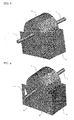
- Fig. 5 is a perspective view showing a case that an airflow duct 15 is not formed in the motor-supporting stand 14
- Fig. 6 is a perspective view showing a case that the airflow duct 15 is formed in the motor-supporting stand 14.
- Table 4 the noise value and the number of revolutions at the air-blowing amount of 16 m 3 /min of the air blown out from the indoor unit, in a case where the airflow duct is present in the motor-supporting stand and a case where the airflow duct is absent therein, are shown.
- the constitution, in which the airflow duct 15 is provided in the motor-supporting stand 14 as described above, may be combined with the constitution of the above-described first embodiment or the second embodiment.
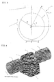
- Fig. 7 is a schematic perspective view illustrating a case where a rib 16 is provided at each of both ends of the tongue portion 8 of the scroll in the present embodiment
- Fig. 8 is a schematic side elevation thereof.
- the rib 16 takes a form of an approximately rectangular parallelepiped shape, and the following formula is satisfied: segment XY ⁇ segment XZ, where a point in the rib 16 most apart from the fan body 11 is defined as a point X, a point in a circular arc portion of the tongue portion 8 most apart from the fan body 11 is defined as a point Y, and a point in the rib 16 nearest to the fan body 11 is defined as a point Z. Furthermore, in Fig.
- a velocity component that is perpendicular to a blowing-out opening 18 in a case where the rib 16 is absent is shown.
- a reverse flow area 20 indicated by a dashed line in the blowing-out opening 18 a flow toward an inner part of the fan from an outer part thereof is shown.
- stream lines, which are formed at a time when smoke is infused from, for example, a segment 21 on the suction opening 17, are shown, so as to prove a reverse flow phenomenon.
- the noise value and the number of revolutions can be reduced by providing a rib.
- the reason is that in a case where the rib is absent and a resistive element to the flow such as a heat exchanger or the like is present, the higher the draft resistance of the resistive element becomes, the more the reverse flow phenomenon, in which the airflow is headed toward the inner part of the fan from the blowing-out opening 18, occurs at the blowing-out opening 18 of the sirocco fan 1 as illustrated in Fig. 9 , and this becomes a cause of increasing the noise value and the number of revolutions. That is, as illustrated in Fig.
- an airflow blown out from gaps between the blades on a main plate side is headed toward both ends of the scroll along the scroll, and in the vicinity of both ends of the tongue portion 8, flows into a gap between the tongue portion 8 and the fan body 11, without flowing toward the blowing-out opening 18.
- the airflow further flows into the gaps between the blades, and is blown out from the gaps between the blades on the main plate side, so that a flow 22 blown out toward the outer part of the scroll is caused.
- the static pressure fluctuation on the wall surface is increased in the vicinity of both ends of the tongue portion, and a flow passing through the gaps between the blades many times is caused, and an air-blowing amount of the airflow that circulates in the inner part of the fan increases.
- the rib 16 it is appropriate for the rib 16 to have a width in the range from 5 to 10 mm. Further, the constitution, in which the rib 16 of the present embodiment is provided, may be combined with any one of the constitutions of the above-described first to third embodiment.
Landscapes
- Engineering & Computer Science (AREA)
- Mechanical Engineering (AREA)
- General Engineering & Computer Science (AREA)
- Chemical & Material Sciences (AREA)
- Combustion & Propulsion (AREA)
- Physics & Mathematics (AREA)
- Thermal Sciences (AREA)
- Structures Of Non-Positive Displacement Pumps (AREA)
- Air-Conditioning Room Units, And Self-Contained Units In General (AREA)
Priority Applications (2)
| Application Number | Priority Date | Filing Date | Title |
|---|---|---|---|
| EP14164771.9A EP2757268B1 (fr) | 2007-03-27 | 2008-03-25 | Ventilateur sirocco et appareil de climatisation |
| EP14164774.3A EP2757269B1 (fr) | 2007-03-27 | 2008-03-25 | Ventilateur sirocco et appareil de climatisation |
Applications Claiming Priority (2)
| Application Number | Priority Date | Filing Date | Title |
|---|---|---|---|
| JP2007081325A JP4906555B2 (ja) | 2007-03-27 | 2007-03-27 | シロッコファン及び空気調和装置 |
| PCT/JP2008/055477 WO2008123208A1 (fr) | 2007-03-27 | 2008-03-25 | Ventilateur sirocco et conditionneur d'air |
Related Child Applications (4)
| Application Number | Title | Priority Date | Filing Date |
|---|---|---|---|
| EP14164771.9A Division EP2757268B1 (fr) | 2007-03-27 | 2008-03-25 | Ventilateur sirocco et appareil de climatisation |
| EP14164771.9A Division-Into EP2757268B1 (fr) | 2007-03-27 | 2008-03-25 | Ventilateur sirocco et appareil de climatisation |
| EP14164774.3A Division-Into EP2757269B1 (fr) | 2007-03-27 | 2008-03-25 | Ventilateur sirocco et appareil de climatisation |
| EP14164774.3A Division EP2757269B1 (fr) | 2007-03-27 | 2008-03-25 | Ventilateur sirocco et appareil de climatisation |
Publications (3)
| Publication Number | Publication Date |
|---|---|
| EP2128451A1 true EP2128451A1 (fr) | 2009-12-02 |
| EP2128451A4 EP2128451A4 (fr) | 2014-01-15 |
| EP2128451B1 EP2128451B1 (fr) | 2017-04-19 |
Family
ID=39830703
Family Applications (3)
| Application Number | Title | Priority Date | Filing Date |
|---|---|---|---|
| EP14164774.3A Active EP2757269B1 (fr) | 2007-03-27 | 2008-03-25 | Ventilateur sirocco et appareil de climatisation |
| EP14164771.9A Active EP2757268B1 (fr) | 2007-03-27 | 2008-03-25 | Ventilateur sirocco et appareil de climatisation |
| EP08722743.5A Not-in-force EP2128451B1 (fr) | 2007-03-27 | 2008-03-25 | Ventilateur sirocco et conditionneur d'air |
Family Applications Before (2)
| Application Number | Title | Priority Date | Filing Date |
|---|---|---|---|
| EP14164774.3A Active EP2757269B1 (fr) | 2007-03-27 | 2008-03-25 | Ventilateur sirocco et appareil de climatisation |
| EP14164771.9A Active EP2757268B1 (fr) | 2007-03-27 | 2008-03-25 | Ventilateur sirocco et appareil de climatisation |
Country Status (8)
| Country | Link |
|---|---|
| EP (3) | EP2757269B1 (fr) |
| JP (1) | JP4906555B2 (fr) |
| KR (1) | KR101179805B1 (fr) |
| CN (1) | CN101595310B (fr) |
| AU (1) | AU2008236109C1 (fr) |
| ES (3) | ES2625932T3 (fr) |
| TW (1) | TW200916663A (fr) |
| WO (1) | WO2008123208A1 (fr) |
Cited By (4)
| Publication number | Priority date | Publication date | Assignee | Title |
|---|---|---|---|---|
| CN112119224A (zh) * | 2018-05-21 | 2020-12-22 | 三菱电机株式会社 | 离心送风机、送风装置、空调装置及制冷循环装置 |
| US11592032B2 (en) | 2017-10-31 | 2023-02-28 | Mitsubishi Electric Corporation | Centrifugal fan, air-sending device, air-conditioning apparatus, and refrigeration cycle apparatus |
| EP4253849A4 (fr) * | 2020-11-27 | 2024-01-17 | Mitsubishi Electric Corporation | Dispositif de climatisation |
| US11994148B2 (en) | 2018-12-19 | 2024-05-28 | Mitsubishi Electric Corporation | Centrifugal fan, air-sending device, air-conditioning apparatus, and refrigeration cycle apparatus |
Families Citing this family (11)
| Publication number | Priority date | Publication date | Assignee | Title |
|---|---|---|---|---|
| CN102865248B (zh) * | 2011-07-06 | 2015-05-13 | 珠海格力电器股份有限公司 | 空调器蜗壳及具有该空调器蜗壳的空调器 |
| KR101698788B1 (ko) * | 2011-10-17 | 2017-01-23 | 엘지전자 주식회사 | 시로코팬 및 그를 갖는 공기조화기 |
| US9039363B2 (en) * | 2012-06-22 | 2015-05-26 | Trane International Inc. | Blower housing |
| JP6425325B2 (ja) * | 2012-12-26 | 2018-11-21 | 新晃工業株式会社 | 空気調和機におけるプラグファンのガイド板部 |
| GB2551281A (en) * | 2015-03-02 | 2017-12-13 | Mitsubishi Electric Corp | Sirocco fan and indoor unit of air conditioner using this sirocco fan |
| CN107477677B (zh) * | 2017-08-25 | 2023-06-06 | 重庆凌达压缩机有限公司 | 一种空调室内机和空调器 |
| WO2019082392A1 (fr) * | 2017-10-27 | 2019-05-02 | 三菱電機株式会社 | Soufflante centrifuge, dispositif de soufflante d'air, dispositif de climatisation, et dispositif à cycle de réfrigération |
| CN107832261B (zh) * | 2017-11-02 | 2020-09-29 | 华东交通大学 | 一种基于小波变换的非平稳排气噪声信号阶次定量提取方法 |
| EP3530956B1 (fr) | 2018-02-26 | 2021-09-22 | Honeywell Technologies Sarl | Roue à aubes pour soufflante radiale et appareil à brûleur à gaz |
| KR102830560B1 (ko) | 2019-07-23 | 2025-07-08 | 삼성전자주식회사 | 의류 관리기 |
| JP7640885B2 (ja) * | 2023-06-30 | 2025-03-06 | ダイキン工業株式会社 | ファンおよび空気調和装置 |
Family Cites Families (14)
| Publication number | Priority date | Publication date | Assignee | Title |
|---|---|---|---|---|
| US3846040A (en) * | 1972-06-16 | 1974-11-05 | D Dennis | Blower housing |
| JPS60153900A (ja) * | 1984-01-21 | 1985-08-13 | 山野 陸三 | 洗濯物用脱水乾燥装置 |
| JPS6480698A (en) * | 1987-09-24 | 1989-03-27 | Tokyo Gas Co Ltd | Automatic supply and recovery device for pipe |
| JPH0341117Y2 (fr) * | 1987-11-19 | 1991-08-29 | ||
| US5449271A (en) * | 1994-12-27 | 1995-09-12 | Carrier Corporation | Transverse fan with randomly varying I-shaped tongue |
| JP3700217B2 (ja) | 1995-10-31 | 2005-09-28 | 株式会社デンソー | 遠心式送風機 |
| JPH109198A (ja) * | 1996-06-26 | 1998-01-13 | Matsushita Seiko Co Ltd | ファンモータの取付支持方法 |
| JP3575986B2 (ja) * | 1998-05-06 | 2004-10-13 | 松下エコシステムズ株式会社 | 多翼送風機 |
| JP3988302B2 (ja) * | 1999-02-17 | 2007-10-10 | 松下電器産業株式会社 | 多翼ファンのスクロールケーシング |
| KR100337287B1 (ko) * | 1999-07-28 | 2002-05-17 | 윤종용 | 원심 송풍기 |
| JP2005273593A (ja) * | 2004-03-26 | 2005-10-06 | Nippon Densan Corp | 遠心ファン |
| KR100591335B1 (ko) * | 2004-06-16 | 2006-06-19 | 엘지전자 주식회사 | 원심 송풍기 |
| JP2006138268A (ja) | 2004-11-12 | 2006-06-01 | Fujitsu General Ltd | 遠心ファン装置 |
| JP2006233835A (ja) * | 2005-02-24 | 2006-09-07 | Matsushita Electric Ind Co Ltd | 送風機 |
-
2007
- 2007-03-27 JP JP2007081325A patent/JP4906555B2/ja not_active Expired - Fee Related
-
2008
- 2008-03-25 KR KR1020097014245A patent/KR101179805B1/ko not_active Expired - Fee Related
- 2008-03-25 ES ES08722743.5T patent/ES2625932T3/es active Active
- 2008-03-25 EP EP14164774.3A patent/EP2757269B1/fr active Active
- 2008-03-25 ES ES14164771T patent/ES2744990T3/es active Active
- 2008-03-25 EP EP14164771.9A patent/EP2757268B1/fr active Active
- 2008-03-25 CN CN200880002818XA patent/CN101595310B/zh not_active Expired - Fee Related
- 2008-03-25 EP EP08722743.5A patent/EP2128451B1/fr not_active Not-in-force
- 2008-03-25 AU AU2008236109A patent/AU2008236109C1/en not_active Ceased
- 2008-03-25 ES ES14164774T patent/ES2749113T3/es active Active
- 2008-03-25 WO PCT/JP2008/055477 patent/WO2008123208A1/fr not_active Ceased
- 2008-03-26 TW TW097110727A patent/TW200916663A/zh not_active IP Right Cessation
Cited By (8)
| Publication number | Priority date | Publication date | Assignee | Title |
|---|---|---|---|---|
| US11592032B2 (en) | 2017-10-31 | 2023-02-28 | Mitsubishi Electric Corporation | Centrifugal fan, air-sending device, air-conditioning apparatus, and refrigeration cycle apparatus |
| CN112119224A (zh) * | 2018-05-21 | 2020-12-22 | 三菱电机株式会社 | 离心送风机、送风装置、空调装置及制冷循环装置 |
| EP3798452A4 (fr) * | 2018-05-21 | 2021-05-12 | Mitsubishi Electric Corporation | Soufflante centrifuge, dispositif de soufflage d'air, dispositif de climatisation, et dispositif à cycle frigorifique |
| AU2018424471B2 (en) * | 2018-05-21 | 2022-01-13 | Mitsubishi Electric Corporation | Centrifugal blower, air-sending device, air-conditioning device, and refrigeration cycle device |
| US11274678B2 (en) | 2018-05-21 | 2022-03-15 | Mitsubishi Electric Corporation | Centrifugal blower, air-sending device, air-conditioning device, and refrigeration cycle device |
| CN112119224B (zh) * | 2018-05-21 | 2022-03-29 | 三菱电机株式会社 | 离心送风机、送风装置、空调装置及制冷循环装置 |
| US11994148B2 (en) | 2018-12-19 | 2024-05-28 | Mitsubishi Electric Corporation | Centrifugal fan, air-sending device, air-conditioning apparatus, and refrigeration cycle apparatus |
| EP4253849A4 (fr) * | 2020-11-27 | 2024-01-17 | Mitsubishi Electric Corporation | Dispositif de climatisation |
Also Published As
| Publication number | Publication date |
|---|---|
| ES2744990T3 (es) | 2020-02-27 |
| ES2749113T3 (es) | 2020-03-19 |
| CN101595310B (zh) | 2013-09-18 |
| EP2128451A4 (fr) | 2014-01-15 |
| EP2757268A2 (fr) | 2014-07-23 |
| AU2008236109A1 (en) | 2008-10-16 |
| CN101595310A (zh) | 2009-12-02 |
| HK1135160A1 (en) | 2010-05-28 |
| KR101179805B1 (ko) | 2012-09-04 |
| AU2008236109C1 (en) | 2011-10-13 |
| EP2128451B1 (fr) | 2017-04-19 |
| EP2757269A2 (fr) | 2014-07-23 |
| JP2008240612A (ja) | 2008-10-09 |
| EP2757268A3 (fr) | 2016-11-16 |
| JP4906555B2 (ja) | 2012-03-28 |
| TWI352780B (fr) | 2011-11-21 |
| KR20090088440A (ko) | 2009-08-19 |
| EP2757268B1 (fr) | 2019-08-07 |
| AU2008236109B2 (en) | 2011-01-27 |
| ES2625932T3 (es) | 2017-07-21 |
| WO2008123208A1 (fr) | 2008-10-16 |
| EP2757269B1 (fr) | 2019-09-04 |
| EP2757269A3 (fr) | 2016-11-16 |
| TW200916663A (en) | 2009-04-16 |
Similar Documents
| Publication | Publication Date | Title |
|---|---|---|
| EP2128451B1 (fr) | Ventilateur sirocco et conditionneur d'air | |
| AU2008236113B2 (en) | Sirocco fan and air conditioner | |
| US20090123285A1 (en) | Double suction type centrifugal fan | |
| JP6304441B1 (ja) | クロスフロー型の送風機及びそれを備えた空気調和装置の室内ユニット | |
| CN109247023B (zh) | 离心送风机、空气调节装置以及制冷循环装置 | |
| JP6472625B2 (ja) | 空気調和機 | |
| EP1243864B1 (fr) | Unité intérieure et conditionneur d'air | |
| KR101045750B1 (ko) | 시로코 팬 및 그것을 이용한 공기 조화 장치 | |
| WO2002081974A1 (fr) | Appareil de climatisation | |
| JP7100068B2 (ja) | 空気調和機 | |
| EP1245908B1 (fr) | Dispositif de climatisation et unité d' intérieur pour celui-ci | |
| JP6925571B1 (ja) | 送風機、室内機および空気調和装置 | |
| JP3621892B2 (ja) | 室内機ユニット及び空気調和機 | |
| KR100402885B1 (ko) | 에어컨 실외기의 축류팬 | |
| HK1135160B (en) | Sirocco fan and air conditioner | |
| JPH03255829A (ja) | 空気調和機用室外ユニット | |
| WO2024189871A1 (fr) | Unité intérieure pour climatiseur et climatiseur équipé de celle-ci | |
| JP6056471B2 (ja) | 冷凍空調装置 | |
| WO2024214236A1 (fr) | Unité intérieure de climatiseur et climatiseur équipé de celle-ci | |
| WO2023223383A1 (fr) | Ventilateur à flux transversal, dispositif de soufflage, et dispositif à cycle de réfrigération | |
| WO2013183090A1 (fr) | Unité d'extérieur pour un dispositif de conditionnement d'air, et dispositif de conditionnement d'air comportant celle-ci | |
| JPH11270871A (ja) | 送風機 | |
| KR20060015123A (ko) | 천정형 에어컨 |
Legal Events
| Date | Code | Title | Description |
|---|---|---|---|
| PUAI | Public reference made under article 153(3) epc to a published international application that has entered the european phase |
Free format text: ORIGINAL CODE: 0009012 |
|
| 17P | Request for examination filed |
Effective date: 20090629 |
|
| AK | Designated contracting states |
Kind code of ref document: A1 Designated state(s): AT BE BG CH CY CZ DE DK EE ES FI FR GB GR HR HU IE IS IT LI LT LU LV MC MT NL NO PL PT RO SE SI SK TR |
|
| DAX | Request for extension of the european patent (deleted) | ||
| A4 | Supplementary search report drawn up and despatched |
Effective date: 20131216 |
|
| RIC1 | Information provided on ipc code assigned before grant |
Ipc: F24F 13/24 20060101ALI20131210BHEP Ipc: F04D 17/08 20060101ALI20131210BHEP Ipc: F24F 7/007 20060101ALI20131210BHEP Ipc: F04D 29/28 20060101ALI20131210BHEP Ipc: F24F 1/00 20110101ALI20131210BHEP Ipc: F04D 29/60 20060101ALI20131210BHEP Ipc: F04D 29/42 20060101ALI20131210BHEP Ipc: F04D 29/44 20060101AFI20131210BHEP Ipc: F04D 29/66 20060101ALI20131210BHEP Ipc: F04D 17/04 20060101ALI20131210BHEP |
|
| GRAP | Despatch of communication of intention to grant a patent |
Free format text: ORIGINAL CODE: EPIDOSNIGR1 |
|
| INTG | Intention to grant announced |
Effective date: 20161019 |
|
| STAA | Information on the status of an ep patent application or granted ep patent |
Free format text: STATUS: GRANT OF PATENT IS INTENDED |
|
| GRAS | Grant fee paid |
Free format text: ORIGINAL CODE: EPIDOSNIGR3 |
|
| GRAA | (expected) grant |
Free format text: ORIGINAL CODE: 0009210 |
|
| STAA | Information on the status of an ep patent application or granted ep patent |
Free format text: STATUS: THE PATENT HAS BEEN GRANTED |
|
| AK | Designated contracting states |
Kind code of ref document: B1 Designated state(s): AT BE BG CH CY CZ DE DK EE ES FI FR GB GR HR HU IE IS IT LI LT LU LV MC MT NL NO PL PT RO SE SI SK TR |
|
| REG | Reference to a national code |
Ref country code: GB Ref legal event code: FG4D |
|
| REG | Reference to a national code |
Ref country code: CH Ref legal event code: EP |
|
| REG | Reference to a national code |
Ref country code: AT Ref legal event code: REF Ref document number: 886254 Country of ref document: AT Kind code of ref document: T Effective date: 20170515 |
|
| REG | Reference to a national code |
Ref country code: IE Ref legal event code: FG4D |
|
| REG | Reference to a national code |
Ref country code: DE Ref legal event code: R096 Ref document number: 602008049829 Country of ref document: DE |
|
| REG | Reference to a national code |
Ref country code: ES Ref legal event code: FG2A Ref document number: 2625932 Country of ref document: ES Kind code of ref document: T3 Effective date: 20170721 |
|
| REG | Reference to a national code |
Ref country code: NL Ref legal event code: MP Effective date: 20170419 |
|
| REG | Reference to a national code |
Ref country code: LT Ref legal event code: MG4D |
|
| REG | Reference to a national code |
Ref country code: AT Ref legal event code: MK05 Ref document number: 886254 Country of ref document: AT Kind code of ref document: T Effective date: 20170419 |
|
| PG25 | Lapsed in a contracting state [announced via postgrant information from national office to epo] |
Ref country code: NL Free format text: LAPSE BECAUSE OF FAILURE TO SUBMIT A TRANSLATION OF THE DESCRIPTION OR TO PAY THE FEE WITHIN THE PRESCRIBED TIME-LIMIT Effective date: 20170419 |
|
| PG25 | Lapsed in a contracting state [announced via postgrant information from national office to epo] |
Ref country code: HR Free format text: LAPSE BECAUSE OF FAILURE TO SUBMIT A TRANSLATION OF THE DESCRIPTION OR TO PAY THE FEE WITHIN THE PRESCRIBED TIME-LIMIT Effective date: 20170419 Ref country code: GR Free format text: LAPSE BECAUSE OF FAILURE TO SUBMIT A TRANSLATION OF THE DESCRIPTION OR TO PAY THE FEE WITHIN THE PRESCRIBED TIME-LIMIT Effective date: 20170720 Ref country code: LT Free format text: LAPSE BECAUSE OF FAILURE TO SUBMIT A TRANSLATION OF THE DESCRIPTION OR TO PAY THE FEE WITHIN THE PRESCRIBED TIME-LIMIT Effective date: 20170419 Ref country code: NO Free format text: LAPSE BECAUSE OF FAILURE TO SUBMIT A TRANSLATION OF THE DESCRIPTION OR TO PAY THE FEE WITHIN THE PRESCRIBED TIME-LIMIT Effective date: 20170719 Ref country code: FI Free format text: LAPSE BECAUSE OF FAILURE TO SUBMIT A TRANSLATION OF THE DESCRIPTION OR TO PAY THE FEE WITHIN THE PRESCRIBED TIME-LIMIT Effective date: 20170419 Ref country code: AT Free format text: LAPSE BECAUSE OF FAILURE TO SUBMIT A TRANSLATION OF THE DESCRIPTION OR TO PAY THE FEE WITHIN THE PRESCRIBED TIME-LIMIT Effective date: 20170419 |
|
| PG25 | Lapsed in a contracting state [announced via postgrant information from national office to epo] |
Ref country code: LV Free format text: LAPSE BECAUSE OF FAILURE TO SUBMIT A TRANSLATION OF THE DESCRIPTION OR TO PAY THE FEE WITHIN THE PRESCRIBED TIME-LIMIT Effective date: 20170419 Ref country code: SE Free format text: LAPSE BECAUSE OF FAILURE TO SUBMIT A TRANSLATION OF THE DESCRIPTION OR TO PAY THE FEE WITHIN THE PRESCRIBED TIME-LIMIT Effective date: 20170419 Ref country code: PL Free format text: LAPSE BECAUSE OF FAILURE TO SUBMIT A TRANSLATION OF THE DESCRIPTION OR TO PAY THE FEE WITHIN THE PRESCRIBED TIME-LIMIT Effective date: 20170419 Ref country code: BG Free format text: LAPSE BECAUSE OF FAILURE TO SUBMIT A TRANSLATION OF THE DESCRIPTION OR TO PAY THE FEE WITHIN THE PRESCRIBED TIME-LIMIT Effective date: 20170719 Ref country code: IS Free format text: LAPSE BECAUSE OF FAILURE TO SUBMIT A TRANSLATION OF THE DESCRIPTION OR TO PAY THE FEE WITHIN THE PRESCRIBED TIME-LIMIT Effective date: 20170819 |
|
| REG | Reference to a national code |
Ref country code: DE Ref legal event code: R097 Ref document number: 602008049829 Country of ref document: DE |
|
| PG25 | Lapsed in a contracting state [announced via postgrant information from national office to epo] |
Ref country code: SK Free format text: LAPSE BECAUSE OF FAILURE TO SUBMIT A TRANSLATION OF THE DESCRIPTION OR TO PAY THE FEE WITHIN THE PRESCRIBED TIME-LIMIT Effective date: 20170419 Ref country code: CZ Free format text: LAPSE BECAUSE OF FAILURE TO SUBMIT A TRANSLATION OF THE DESCRIPTION OR TO PAY THE FEE WITHIN THE PRESCRIBED TIME-LIMIT Effective date: 20170419 Ref country code: RO Free format text: LAPSE BECAUSE OF FAILURE TO SUBMIT A TRANSLATION OF THE DESCRIPTION OR TO PAY THE FEE WITHIN THE PRESCRIBED TIME-LIMIT Effective date: 20170419 Ref country code: EE Free format text: LAPSE BECAUSE OF FAILURE TO SUBMIT A TRANSLATION OF THE DESCRIPTION OR TO PAY THE FEE WITHIN THE PRESCRIBED TIME-LIMIT Effective date: 20170419 Ref country code: DK Free format text: LAPSE BECAUSE OF FAILURE TO SUBMIT A TRANSLATION OF THE DESCRIPTION OR TO PAY THE FEE WITHIN THE PRESCRIBED TIME-LIMIT Effective date: 20170419 |
|
| PLBE | No opposition filed within time limit |
Free format text: ORIGINAL CODE: 0009261 |
|
| STAA | Information on the status of an ep patent application or granted ep patent |
Free format text: STATUS: NO OPPOSITION FILED WITHIN TIME LIMIT |
|
| 26N | No opposition filed |
Effective date: 20180122 |
|
| PG25 | Lapsed in a contracting state [announced via postgrant information from national office to epo] |
Ref country code: SI Free format text: LAPSE BECAUSE OF FAILURE TO SUBMIT A TRANSLATION OF THE DESCRIPTION OR TO PAY THE FEE WITHIN THE PRESCRIBED TIME-LIMIT Effective date: 20170419 |
|
| REG | Reference to a national code |
Ref country code: DE Ref legal event code: R119 Ref document number: 602008049829 Country of ref document: DE |
|
| REG | Reference to a national code |
Ref country code: CH Ref legal event code: PL |
|
| PG25 | Lapsed in a contracting state [announced via postgrant information from national office to epo] |
Ref country code: MC Free format text: LAPSE BECAUSE OF FAILURE TO SUBMIT A TRANSLATION OF THE DESCRIPTION OR TO PAY THE FEE WITHIN THE PRESCRIBED TIME-LIMIT Effective date: 20170419 |
|
| REG | Reference to a national code |
Ref country code: BE Ref legal event code: MM Effective date: 20180331 |
|
| REG | Reference to a national code |
Ref country code: IE Ref legal event code: MM4A |
|
| PG25 | Lapsed in a contracting state [announced via postgrant information from national office to epo] |
Ref country code: LU Free format text: LAPSE BECAUSE OF NON-PAYMENT OF DUE FEES Effective date: 20180325 |
|
| PG25 | Lapsed in a contracting state [announced via postgrant information from national office to epo] |
Ref country code: IE Free format text: LAPSE BECAUSE OF NON-PAYMENT OF DUE FEES Effective date: 20180325 Ref country code: DE Free format text: LAPSE BECAUSE OF NON-PAYMENT OF DUE FEES Effective date: 20181002 |
|
| REG | Reference to a national code |
Ref country code: GB Ref legal event code: 746 Effective date: 20190122 |
|
| PG25 | Lapsed in a contracting state [announced via postgrant information from national office to epo] |
Ref country code: CH Free format text: LAPSE BECAUSE OF NON-PAYMENT OF DUE FEES Effective date: 20180331 Ref country code: LI Free format text: LAPSE BECAUSE OF NON-PAYMENT OF DUE FEES Effective date: 20180331 Ref country code: BE Free format text: LAPSE BECAUSE OF NON-PAYMENT OF DUE FEES Effective date: 20180331 |
|
| REG | Reference to a national code |
Ref country code: ES Ref legal event code: GC2A Effective date: 20190416 |
|
| PG25 | Lapsed in a contracting state [announced via postgrant information from national office to epo] |
Ref country code: FR Free format text: LAPSE BECAUSE OF NON-PAYMENT OF DUE FEES Effective date: 20180331 |
|
| PG25 | Lapsed in a contracting state [announced via postgrant information from national office to epo] |
Ref country code: MT Free format text: LAPSE BECAUSE OF NON-PAYMENT OF DUE FEES Effective date: 20180325 |
|
| PG25 | Lapsed in a contracting state [announced via postgrant information from national office to epo] |
Ref country code: TR Free format text: LAPSE BECAUSE OF FAILURE TO SUBMIT A TRANSLATION OF THE DESCRIPTION OR TO PAY THE FEE WITHIN THE PRESCRIBED TIME-LIMIT Effective date: 20170419 |
|
| PG25 | Lapsed in a contracting state [announced via postgrant information from national office to epo] |
Ref country code: PT Free format text: LAPSE BECAUSE OF FAILURE TO SUBMIT A TRANSLATION OF THE DESCRIPTION OR TO PAY THE FEE WITHIN THE PRESCRIBED TIME-LIMIT Effective date: 20170419 Ref country code: HU Free format text: LAPSE BECAUSE OF FAILURE TO SUBMIT A TRANSLATION OF THE DESCRIPTION OR TO PAY THE FEE WITHIN THE PRESCRIBED TIME-LIMIT; INVALID AB INITIO Effective date: 20080325 |
|
| PG25 | Lapsed in a contracting state [announced via postgrant information from national office to epo] |
Ref country code: CY Free format text: LAPSE BECAUSE OF FAILURE TO SUBMIT A TRANSLATION OF THE DESCRIPTION OR TO PAY THE FEE WITHIN THE PRESCRIBED TIME-LIMIT Effective date: 20170419 |
|
| P01 | Opt-out of the competence of the unified patent court (upc) registered |
Effective date: 20230512 |
|
| PGFP | Annual fee paid to national office [announced via postgrant information from national office to epo] |
Ref country code: ES Payment date: 20230404 Year of fee payment: 16 |
|
| PGFP | Annual fee paid to national office [announced via postgrant information from national office to epo] |
Ref country code: GB Payment date: 20240201 Year of fee payment: 17 |
|
| PGFP | Annual fee paid to national office [announced via postgrant information from national office to epo] |
Ref country code: IT Payment date: 20240212 Year of fee payment: 17 |
|
| PG25 | Lapsed in a contracting state [announced via postgrant information from national office to epo] |
Ref country code: ES Free format text: LAPSE BECAUSE OF NON-PAYMENT OF DUE FEES Effective date: 20240326 |
|
| GBPC | Gb: european patent ceased through non-payment of renewal fee |
Effective date: 20250325 |
|
| PG25 | Lapsed in a contracting state [announced via postgrant information from national office to epo] |
Ref country code: GB Free format text: LAPSE BECAUSE OF NON-PAYMENT OF DUE FEES Effective date: 20250325 |
|
| PG25 | Lapsed in a contracting state [announced via postgrant information from national office to epo] |
Ref country code: IT Free format text: LAPSE BECAUSE OF NON-PAYMENT OF DUE FEES Effective date: 20250325 |