EP2128457B1 - Elément de fixation constitué d'un boulon d'ancrage et d'un élément de serrage - Google Patents
Elément de fixation constitué d'un boulon d'ancrage et d'un élément de serrage Download PDFInfo
- Publication number
- EP2128457B1 EP2128457B1 EP20090006155 EP09006155A EP2128457B1 EP 2128457 B1 EP2128457 B1 EP 2128457B1 EP 20090006155 EP20090006155 EP 20090006155 EP 09006155 A EP09006155 A EP 09006155A EP 2128457 B1 EP2128457 B1 EP 2128457B1
- Authority
- EP
- European Patent Office
- Prior art keywords
- wedge
- anchor bolt
- attachment element
- element according
- longitudinal axis
- Prior art date
- Legal status (The legal status is an assumption and is not a legal conclusion. Google has not performed a legal analysis and makes no representation as to the accuracy of the status listed.)
- Not-in-force
Links
- 229910000831 Steel Inorganic materials 0.000 claims description 7
- 239000010959 steel Substances 0.000 claims description 7
- 230000003746 surface roughness Effects 0.000 claims description 3
- 239000013589 supplement Substances 0.000 claims 1
- 230000000694 effects Effects 0.000 description 5
- 239000000463 material Substances 0.000 description 3
- 238000006073 displacement reaction Methods 0.000 description 2
- 238000003780 insertion Methods 0.000 description 2
- 230000037431 insertion Effects 0.000 description 2
- 239000007787 solid Substances 0.000 description 2
- 238000013459 approach Methods 0.000 description 1
- 230000015572 biosynthetic process Effects 0.000 description 1
- 230000001419 dependent effect Effects 0.000 description 1
- 238000013461 design Methods 0.000 description 1
- 238000011161 development Methods 0.000 description 1
- 238000005553 drilling Methods 0.000 description 1
- 239000000428 dust Substances 0.000 description 1
- 238000000034 method Methods 0.000 description 1
- 238000003825 pressing Methods 0.000 description 1
- 230000007704 transition Effects 0.000 description 1
Images


Classifications
-
- F—MECHANICAL ENGINEERING; LIGHTING; HEATING; WEAPONS; BLASTING
- F16—ENGINEERING ELEMENTS AND UNITS; GENERAL MEASURES FOR PRODUCING AND MAINTAINING EFFECTIVE FUNCTIONING OF MACHINES OR INSTALLATIONS; THERMAL INSULATION IN GENERAL
- F16B—DEVICES FOR FASTENING OR SECURING CONSTRUCTIONAL ELEMENTS OR MACHINE PARTS TOGETHER, e.g. NAILS, BOLTS, CIRCLIPS, CLAMPS, CLIPS OR WEDGES; JOINTS OR JOINTING
- F16B13/00—Dowels or other devices fastened in walls or the like by inserting them in holes made therein for that purpose
- F16B13/04—Dowels or other devices fastened in walls or the like by inserting them in holes made therein for that purpose with parts gripping in the hole or behind the reverse side of the wall after inserting from the front
- F16B13/08—Dowels or other devices fastened in walls or the like by inserting them in holes made therein for that purpose with parts gripping in the hole or behind the reverse side of the wall after inserting from the front with separate or non-separate gripping parts moved into their final position in relation to the body of the device without further manual operation
- F16B13/0816—Dowels or other devices fastened in walls or the like by inserting them in holes made therein for that purpose with parts gripping in the hole or behind the reverse side of the wall after inserting from the front with separate or non-separate gripping parts moved into their final position in relation to the body of the device without further manual operation with a wedging drive-pin
Definitions
- the invention relates to a fastening element according to the preamble of claim 1.
- the clamping wedge on a predetermined breaking zone, which has a flat wedge-shaped portion having two spaced apart in the direction of the central longitudinal axis of predetermined breaking points, which are transverse to the central longitudinal axis and substantially parallel to extend to the rear end of the anchor bolt surface.
- a predetermined breaking zone which has a flat wedge-shaped portion having two spaced apart in the direction of the central longitudinal axis of predetermined breaking points, which are transverse to the central longitudinal axis and substantially parallel to extend to the rear end of the anchor bolt surface.
- a fastener is known, similar to that of the EP 1 204 825 B1 known fastening element is configured. It has a clamping wedge, which contains a predetermined breaking point which is formed by a web extending parallel to the central longitudinal axis. This web is bounded by incisions, which each have a quarter-circle inwardly in the direction of the central longitudinal axis curved surfaces. When breaking this target breaking point, the two parts of the clamping wedge are pushed together in the axial direction. The purpose of this target breaking point is solely to allow the setting process in solid receiving material, a rearward movement of the rear portion of the clamping wedge in the setting direction.
- the invention has the object of providing a fastener of the generic type so that it is inexpensive to produce and can be set with high pull-out resistance.
- the formation of the clamping wedge of undecorated and unhardened steel promotes the effect according to the invention, because it is ensured that the bridge serving as the target breakage point is actually also severed and possibly locked under a certain plastic deformation with the bore wall, as it were .
- the choice of material according to the invention for the clamping wedge also makes it possible to rivet the clamping wedge against the flange when driving in, which also precludes unintentional detachment of the rear part of the clamping wedge.
- the formed on the clamping wedge brake surface causes the broken off the front part of the clamping wedge is held in the borehole at the first possible release of the fastener.
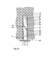
- the fastening element shown in the drawing has an anchor bolt 1 and a clamping wedge 2.
- the anchor bolt 1 consists in its basic structure of a solid part-circle cylinder with a central longitudinal axis 3, which is also referred to for simplicity as the central longitudinal axis 3 of the entire fastener.
- the anchor bolt 1 has at its rear end 4 an annular, radially outwardly projecting flange 5, which is formed integrally with the anchor bolt 1, for example by appropriate deformation. From the rear end 4 of the anchor bolt 1 extends over about half to two-thirds of its total length L a surface 6 parallel to the axis 3, in the vicinity, so that the cylindrical surface 7 of the anchor bolt 1 in this area only about 190 to 200 ° Circumferential angle extends.
- a wedge surface 9 which is therefore inclined from the front end 10 of the anchor bolt 1 to the axis 3.
- the wedge surface 9 and the surface 6 are flat, but they do not have to be.
- the clamping wedge 2 is also formed by a part-circular cylinder, as from the 3 and 4 evident. But the diameter of its associated cylinder is slightly smaller than that of the anchor bolt 1, as is apparent from Fig. 2 and 3 results. Its outer surface 11 is thus also a part-cylinder surface, the generatrices thus - parallel to each other - as in the case of the outer surface of the anchor bolt 1 formed by the cylindrical surface 7.
- the clamping wedge 2 has a contact surface 12 which is adapted to the surface 6 of the anchor bolt 1. This contact surface 12 extends from the rear end 13 of the clamping wedge 2 in ungep Schwarztem state of the fastener to the transition from the surface 6 in the wedge surface 9 of the anchor bolt 1.
- a spreading surface 15 which at least partially abuts the wedge surface 9 of the anchor bolt 1 in ungep Sanderstem state of the fastener.
- the rear end 13 of the clamping wedge 2 is in the unsp Suntem state of the fastener to the rear, to a maximum impact area 16 on the flange 5 before.
- the front end 17 of the clamping wedge 2 is in this case behind the front end 10 of the anchor bolt 1;
- the length 1 of the clamping wedge 2 is slightly larger than the total length L of the anchor bolt 1.
- the length of the spreading surface 15 is smaller than the length of the wedge surface 9 respectively in the direction of the axis 3, while the length of the Contact surface 12 is significantly larger than the length of the surface 6, also seen here in each case in the direction of the axis 3.
- the clamping wedge 2 has in the section in front of the spreading surface 15, a transverse-spreading zone 18, which will be described below.
- the flange 5 has a passage recess 19 for the clamping wedge 2.
- This recess 19, like the clamping wedge 2, has a part-circular cross-section, but its radius is slightly larger than that of the clamping wedge 2, so that its outer surface 11 has a clearance 20 of 0.2 to 0.4 mm relative to the recess 19, like out Fig. 3 is recognizable.
- the clamping wedge 2, in the region of the flange 5 in the unspread state of the fastening element, has two projections 21, which are formed by the contact surface 12, whereby small recesses 22 are formed between these projections 21 and the contact surface 12. These projections have in the direction of the axis 3 a slightly greater length than the thickness of the flange 5 corresponds.
- these projections 21 In the unmounted state of the clamping wedge 2, these projections 21 have a slight oversize relative to the cross-sectional edge of the recess 19 so that they are slightly deformed during insertion of the clamping wedge 2 from the rear end 4 of the anchor bolt 1 in the recess 19, whereby the clamping wedge 2 very firmly with the Anchor bolt 1 is connected in the axial direction. How out Fig. 3 it can be seen, the projections 21 but only against a small portion of the recess 19, while the largest part of the outer surface 11 of the clamping wedge 2 opposite the recess 19 is exposed.
- the transverse expansion zone 18 of the clamping wedge 2 consists of two incisions 23, 24, which are arranged mirror-symmetrically to each other and which are formed in the shape of a right triangle.
- a transverse surface 25 or 26 of each incision 23, 24 extends transversely, ie perpendicular to the central longitudinal axis 3 and that up to this, as from Fig. 2 evident.
- Of the axis 3 associated end of the respective transverse surface 25 extends an inclined surface 27 and 28 toward the rear end 13 of the clamping wedge 2 and toward the front portion 14 of the clamping wedge 2.
- the distance a of the transverse surfaces 25, 26 from each other in the direction of the central longitudinal axis 3 is relatively small.
- the web 29 thus has a length a and at its thickest point a thickness b. This web 29 forms a desired breaking point 30th
- a fine corrugation 32 is formed, which extends in the direction of the central longitudinal axis 3 approximately over the length of the wedge surface 9.
- This corrugation 32 may be formed in the manner of a rectangular toothing 33 or in the manner of a saw toothing 34.
- a brake surface 35 projecting outwards relative to the outer surface 11 is formed, which merges with an edge 36 at its rear end 13 of the clamping wedge 2 into the outer surface 11 , wherein by the edge 36 a pronounced heel is created, which plays a kind of barb function.
- the braking surface 35 protrudes with respect to the outer surface 11 by a dimension e, for which 0.1 mm ⁇ e ⁇ 0.3 mm.
- the braking surface itself is provided with a surface roughness 37 having a roughness depth of 30 microns to 45 microns, and preferably of 36 microns.
- a bore 39 is introduced, whose diameter is slightly larger than the diameter of the anchor bolt 1.
- a part 40 to be fastened which has a bore 39 corresponding hole, which is optionally drilled simultaneously with the bore 39, so brought against the ceiling 38 that hole and bore 39 overlap.
- unspread fastener inserted through the hole in the bore 39, wherein the front end 10 of the anchor bolt 1 is inserted first. The insertion is terminated when the part 40 is pressed against the ceiling 38 by means of the flange 5.
- the anchor bolt 1 is loaded from the outside by a correspondingly large force, then this leads to an additional spreading effect between the front part 42 and the anchor bolt 1, since the front part 42 anchored with its end 44 in the bore wall as it were form-fit, a displacement of the front part 42 in the direction of the bore 39 also excluded.
- the corrugation 32 also achieves an additional increase in the frictional forces between the bore wall 41 and the anchor bolt 1.
- the wedging effect is intensified by the braking surface 35. Its edge 36 digs in addition to the bore wall 41 a.
- the front part 42 of the clamping wedge 2 is thus kept extremely safe in the bore 39.
- the shear through of the clamping wedge 2 in the region of the predetermined breaking point 30 formed by the web 29 is ensured by the fact that the clamping wedge 2 consists of undegraded and unhardened steel, which is therefore relatively soft.
- a tensile strength of about 400 to 600 N / mm 2 applies, the shear strength usually being in the range of 60% of the tensile strength.
- the surface to be sheared of the web 29 is about 5 to 6 mm.
Landscapes
- Engineering & Computer Science (AREA)
- General Engineering & Computer Science (AREA)
- Mechanical Engineering (AREA)
- Clamps And Clips (AREA)
- Dowels (AREA)
- Joining Of Building Structures In Genera (AREA)
Claims (10)
- Elément de fixation constitué d'un boulon d'ancrage (1) et d'un élément de serrage (2), un collet (5) comprenant un évidement pour le passage (19) de l'élément de serrage (2) étant prévu à l'extrémité arrière (4) du boulon d'ancrage (1), le boulon d'ancrage (1) étant pourvu d'un surface inclinée (9) dans sa partie avant (8), qui est inclinée vers l'axe longitudinal central (3) du boulon d'ancrage (1) à partir de son extrémité avant (10) en direction de l'extrémité arrière (4), une surface (6), s'étendant dans l'ensemble parallèlement à l'axe longitudinal central (3) jusqu'à l'extrémité arrière (4), poursuivant cette surface inclinée (9), et l'élément de serrage (2), à l'état non écarté complétant le boulon d'ancrage (1) pour former un profil à peu près cylindrique, et s'appuyant dans ce but, grâce à une surface d'appui (12) contre la surface (6) parallèle à l'axe, et grâce à une surface d'écartement (15) contre la surface inclinée (9), l'extrémité avant (17) de l'élément de serrage (2) ne s'étendant pas jusqu'à l'extrémité avant (10) du boulon d'ancrage (1) et l'extrémité arrière (13) de l'élément de serrage (2) dépassant du collet (5) et l'élément de serrage (2) présentant un point de rupture (30),
caractérisé en ce
que le point de rupture (30) est formé par une entretoise (29) s'étendant parallèle à l'axe longitudinal central (3), entretoise qui est délimitée des deux côtés par des encoches (23, 24), l'une en face de l'autre, dans l'élément de serrage (2), qui présentent des surfaces inclinées (27, 28) formées planes et parallèles entre elles, s'étendant de manière inclinée par rapport à l'axe longitudinal central (3),
que l'élément de serrage (2) présente sur sa surface externe (11) une surface de freinage (35) dépassant vers l'extérieur dans la partie de son extrémité avant (17), et
que l'élément de serrage (2) est constitué d'un acier non durci et non traité. - Elément de fixation selon la revendication 1 caractérisé en ce
que le boulon d'ancrage (1) présente un crantage (32) d'une profondeur d sur sa partie avant (10) sur la face arrière (31) à l'opposé de sa surface inclinée (2). - Elément de fixation selon la revendication 2 caractérisé en ce
que le crantage (32) est conçu sous la forme d'une denture rectangulaire (33). - Elément de fixation selon la revendication 2 caractérisé en ce
que le crantage (32) est conçu sous la forme d'une denture en dents de scie (34). - Elément de fixation selon l'une des revendications de 2 à 4 caractérisé en ce
que l'on ait pour la profondeur d du crantage (32) : 0,2 mm ≤ d ≤ 0,4. - Elément de fixation selon la revendication 1 caractérisé en ce
que la surface de freinage (35) présente une rugosité de surface (37) entre 30 µm et 45 µm, et présente de préférence une rugosité de 36 µm. - Elément de fixation selon les revendications 1 ou 6 caractérisé en ce que la surface de freinage (35) dépasse au niveau de la surface externe par un rebord (36).
- Elément de fixation selon l'une des revendications 1 ou 6 ou 7 caractérisé en ce
que la surface de freinage (35) dépasse au niveau de la surface externe (11) d'une dimension e pour laquelle on a : 0,1 mm ≤ e ≤ 0,3 mm. - Elément de fixation selon l'une des revendications de 1 à 8 caractérisé en ce
que les surfaces inclinées (27, 28) font un angle α par rapport à l'axe longitudinal central (3), pour lequel on a : 25° ≤ α ≤ 35° et de préférence α = 30°. - Elément de fixation selon l'une des revendications de 1 à 9 caractérisé en ce
que l'entretoise (29) s'étend dans l'axe longitudinal central (3).
Applications Claiming Priority (1)
| Application Number | Priority Date | Filing Date | Title |
|---|---|---|---|
| DE102008025765A DE102008025765A1 (de) | 2008-05-29 | 2008-05-29 | Befestigungselement, bestehend aus einem Ankerbolzen und einem Klemmkeil |
Publications (3)
| Publication Number | Publication Date |
|---|---|
| EP2128457A2 EP2128457A2 (fr) | 2009-12-02 |
| EP2128457A3 EP2128457A3 (fr) | 2011-12-28 |
| EP2128457B1 true EP2128457B1 (fr) | 2013-02-20 |
Family
ID=41061146
Family Applications (1)
| Application Number | Title | Priority Date | Filing Date |
|---|---|---|---|
| EP20090006155 Not-in-force EP2128457B1 (fr) | 2008-05-29 | 2009-05-06 | Elément de fixation constitué d'un boulon d'ancrage et d'un élément de serrage |
Country Status (2)
| Country | Link |
|---|---|
| EP (1) | EP2128457B1 (fr) |
| DE (1) | DE102008025765A1 (fr) |
Families Citing this family (2)
| Publication number | Priority date | Publication date | Assignee | Title |
|---|---|---|---|---|
| JP6227268B2 (ja) * | 2013-03-28 | 2017-11-08 | 東京製綱株式会社 | 高耐力アンカー |
| DE102015221890A1 (de) | 2015-11-06 | 2017-05-11 | Toge Dübel Gmbh & Co. Kg | Klemmanker zum Verankern in einem Bohrloch sowie Anordnung mit einem derartigen Klemmanker |
Family Cites Families (5)
| Publication number | Priority date | Publication date | Assignee | Title |
|---|---|---|---|---|
| DE2913090A1 (de) | 1979-04-02 | 1980-10-16 | Hilti Ag | Befestigungselement mit ankerbolzen und spreizkeil |
| DE19517216A1 (de) | 1995-05-11 | 1996-11-14 | Hilti Ag | Befestigungselement mit Ankerbolzen und Spreizkeil |
| DE19531693A1 (de) * | 1995-08-29 | 1997-03-06 | Toge Duebel A Gerhard Gmbh | Befestigungselement |
| AT406409B (de) * | 1998-05-06 | 2000-05-25 | Schlager Josef | Einrichtung zum einschlagen von keildübeln |
| ATE230826T1 (de) | 1999-10-26 | 2003-01-15 | Toge Duebel A Gerhard Kg | Befestigungselement |
-
2008
- 2008-05-29 DE DE102008025765A patent/DE102008025765A1/de not_active Ceased
-
2009
- 2009-05-06 EP EP20090006155 patent/EP2128457B1/fr not_active Not-in-force
Also Published As
| Publication number | Publication date |
|---|---|
| EP2128457A3 (fr) | 2011-12-28 |
| EP2128457A2 (fr) | 2009-12-02 |
| DE102008025765A1 (de) | 2009-12-10 |
Similar Documents
| Publication | Publication Date | Title |
|---|---|---|
| EP2513497B1 (fr) | Élément de fixation | |
| DE102011005999A1 (de) | Spreizdübel | |
| DE3124823A1 (de) | Spreizduebel | |
| EP3620669B1 (fr) | Ancre extensible | |
| EP2044270B1 (fr) | Système de fixation et procédé de montage de plaques de matériau d'isolation | |
| EP3770448A1 (fr) | Système de liaison pour la liaison mécanique de deux matériaux | |
| EP1375932B1 (fr) | Elément de fixation | |
| EP2478163B1 (fr) | Rail d'ancrage à noyer | |
| EP2128457B1 (fr) | Elément de fixation constitué d'un boulon d'ancrage et d'un élément de serrage | |
| EP1412644A1 (fr) | Cheville a expansion | |
| DE3139174C2 (de) | Ankerbolzen | |
| EP0905386A1 (fr) | Cheville d'expansion | |
| EP0908634B1 (fr) | Cheville à enfoncer | |
| EP0262444B1 (fr) | Dispositif d'ancrage, notamment cheville | |
| EP2549127A2 (fr) | Elément de fixation destiné à la fixation d'une plaque isolante | |
| EP0283720A2 (fr) | Elément de fixation composé d'un boulon d'ancrage et d'une clavette de coincement | |
| EP3217027A1 (fr) | Élement de revetement large destine a entourer une tige d'ancrage | |
| DE2637797C3 (de) | Spreizdübel | |
| DE19536786A1 (de) | Befestigungselement mit Spreizelement | |
| EP0170665A1 (fr) | Cheville de fermeture de moule pour du beton | |
| EP0737817B1 (fr) | Dispositif de fixation avec élément d'expansion | |
| WO2004106754A1 (fr) | Ancre extensible en metal et son outil de mise en place | |
| EP1213494B1 (fr) | Elément de fixation | |
| DE19531693A1 (de) | Befestigungselement | |
| EP3165779B1 (fr) | Ancrage de serrage à ancrer dans un trou d'alésage et système comprenant un tel ancrage de serrage |
Legal Events
| Date | Code | Title | Description |
|---|---|---|---|
| PUAI | Public reference made under article 153(3) epc to a published international application that has entered the european phase |
Free format text: ORIGINAL CODE: 0009012 |
|
| AK | Designated contracting states |
Kind code of ref document: A2 Designated state(s): AT BE BG CH CY CZ DE DK EE ES FI FR GB GR HR HU IE IS IT LI LT LU LV MC MK MT NL NO PL PT RO SE SI SK TR |
|
| PUAL | Search report despatched |
Free format text: ORIGINAL CODE: 0009013 |
|
| AK | Designated contracting states |
Kind code of ref document: A3 Designated state(s): AT BE BG CH CY CZ DE DK EE ES FI FR GB GR HR HU IE IS IT LI LT LU LV MC MK MT NL NO PL PT RO SE SI SK TR |
|
| AX | Request for extension of the european patent |
Extension state: AL BA RS |
|
| RIC1 | Information provided on ipc code assigned before grant |
Ipc: F16B 13/08 20060101AFI20111118BHEP |
|
| 17P | Request for examination filed |
Effective date: 20120224 |
|
| GRAP | Despatch of communication of intention to grant a patent |
Free format text: ORIGINAL CODE: EPIDOSNIGR1 |
|
| GRAS | Grant fee paid |
Free format text: ORIGINAL CODE: EPIDOSNIGR3 |
|
| GRAA | (expected) grant |
Free format text: ORIGINAL CODE: 0009210 |
|
| AK | Designated contracting states |
Kind code of ref document: B1 Designated state(s): AT BE BG CH CY CZ DE DK EE ES FI FR GB GR HR HU IE IS IT LI LT LU LV MC MK MT NL NO PL PT RO SE SI SK TR |
|
| REG | Reference to a national code |
Ref country code: GB Ref legal event code: FG4D Free format text: NOT ENGLISH |
|
| REG | Reference to a national code |
Ref country code: CH Ref legal event code: EP |
|
| REG | Reference to a national code |
Ref country code: AT Ref legal event code: REF Ref document number: 597686 Country of ref document: AT Kind code of ref document: T Effective date: 20130315 |
|
| REG | Reference to a national code |
Ref country code: IE Ref legal event code: FG4D Free format text: LANGUAGE OF EP DOCUMENT: GERMAN |
|
| REG | Reference to a national code |
Ref country code: DE Ref legal event code: R096 Ref document number: 502009006262 Country of ref document: DE Effective date: 20130418 |
|
| REG | Reference to a national code |
Ref country code: NL Ref legal event code: T3 |
|
| REG | Reference to a national code |
Ref country code: LT Ref legal event code: MG4D |
|
| PG25 | Lapsed in a contracting state [announced via postgrant information from national office to epo] |
Ref country code: NO Free format text: LAPSE BECAUSE OF FAILURE TO SUBMIT A TRANSLATION OF THE DESCRIPTION OR TO PAY THE FEE WITHIN THE PRESCRIBED TIME-LIMIT Effective date: 20130520 Ref country code: BG Free format text: LAPSE BECAUSE OF FAILURE TO SUBMIT A TRANSLATION OF THE DESCRIPTION OR TO PAY THE FEE WITHIN THE PRESCRIBED TIME-LIMIT Effective date: 20130520 Ref country code: SE Free format text: LAPSE BECAUSE OF FAILURE TO SUBMIT A TRANSLATION OF THE DESCRIPTION OR TO PAY THE FEE WITHIN THE PRESCRIBED TIME-LIMIT Effective date: 20130220 Ref country code: LT Free format text: LAPSE BECAUSE OF FAILURE TO SUBMIT A TRANSLATION OF THE DESCRIPTION OR TO PAY THE FEE WITHIN THE PRESCRIBED TIME-LIMIT Effective date: 20130220 Ref country code: ES Free format text: LAPSE BECAUSE OF FAILURE TO SUBMIT A TRANSLATION OF THE DESCRIPTION OR TO PAY THE FEE WITHIN THE PRESCRIBED TIME-LIMIT Effective date: 20130531 Ref country code: IS Free format text: LAPSE BECAUSE OF FAILURE TO SUBMIT A TRANSLATION OF THE DESCRIPTION OR TO PAY THE FEE WITHIN THE PRESCRIBED TIME-LIMIT Effective date: 20130620 |
|
| PG25 | Lapsed in a contracting state [announced via postgrant information from national office to epo] |
Ref country code: LV Free format text: LAPSE BECAUSE OF FAILURE TO SUBMIT A TRANSLATION OF THE DESCRIPTION OR TO PAY THE FEE WITHIN THE PRESCRIBED TIME-LIMIT Effective date: 20130220 Ref country code: GR Free format text: LAPSE BECAUSE OF FAILURE TO SUBMIT A TRANSLATION OF THE DESCRIPTION OR TO PAY THE FEE WITHIN THE PRESCRIBED TIME-LIMIT Effective date: 20130521 Ref country code: PT Free format text: LAPSE BECAUSE OF FAILURE TO SUBMIT A TRANSLATION OF THE DESCRIPTION OR TO PAY THE FEE WITHIN THE PRESCRIBED TIME-LIMIT Effective date: 20130620 Ref country code: FI Free format text: LAPSE BECAUSE OF FAILURE TO SUBMIT A TRANSLATION OF THE DESCRIPTION OR TO PAY THE FEE WITHIN THE PRESCRIBED TIME-LIMIT Effective date: 20130220 Ref country code: SI Free format text: LAPSE BECAUSE OF FAILURE TO SUBMIT A TRANSLATION OF THE DESCRIPTION OR TO PAY THE FEE WITHIN THE PRESCRIBED TIME-LIMIT Effective date: 20130220 Ref country code: PL Free format text: LAPSE BECAUSE OF FAILURE TO SUBMIT A TRANSLATION OF THE DESCRIPTION OR TO PAY THE FEE WITHIN THE PRESCRIBED TIME-LIMIT Effective date: 20130220 |
|
| PG25 | Lapsed in a contracting state [announced via postgrant information from national office to epo] |
Ref country code: HR Free format text: LAPSE BECAUSE OF FAILURE TO SUBMIT A TRANSLATION OF THE DESCRIPTION OR TO PAY THE FEE WITHIN THE PRESCRIBED TIME-LIMIT Effective date: 20130220 |
|
| PG25 | Lapsed in a contracting state [announced via postgrant information from national office to epo] |
Ref country code: SK Free format text: LAPSE BECAUSE OF FAILURE TO SUBMIT A TRANSLATION OF THE DESCRIPTION OR TO PAY THE FEE WITHIN THE PRESCRIBED TIME-LIMIT Effective date: 20130220 Ref country code: RO Free format text: LAPSE BECAUSE OF FAILURE TO SUBMIT A TRANSLATION OF THE DESCRIPTION OR TO PAY THE FEE WITHIN THE PRESCRIBED TIME-LIMIT Effective date: 20130220 Ref country code: DK Free format text: LAPSE BECAUSE OF FAILURE TO SUBMIT A TRANSLATION OF THE DESCRIPTION OR TO PAY THE FEE WITHIN THE PRESCRIBED TIME-LIMIT Effective date: 20130220 Ref country code: EE Free format text: LAPSE BECAUSE OF FAILURE TO SUBMIT A TRANSLATION OF THE DESCRIPTION OR TO PAY THE FEE WITHIN THE PRESCRIBED TIME-LIMIT Effective date: 20130220 Ref country code: CZ Free format text: LAPSE BECAUSE OF FAILURE TO SUBMIT A TRANSLATION OF THE DESCRIPTION OR TO PAY THE FEE WITHIN THE PRESCRIBED TIME-LIMIT Effective date: 20130220 |
|
| PG25 | Lapsed in a contracting state [announced via postgrant information from national office to epo] |
Ref country code: CY Free format text: LAPSE BECAUSE OF FAILURE TO SUBMIT A TRANSLATION OF THE DESCRIPTION OR TO PAY THE FEE WITHIN THE PRESCRIBED TIME-LIMIT Effective date: 20130220 |
|
| BERE | Be: lapsed |
Owner name: TOGE-DUBEL A. GERHARD K.G. Effective date: 20130531 |
|
| PLBE | No opposition filed within time limit |
Free format text: ORIGINAL CODE: 0009261 |
|
| STAA | Information on the status of an ep patent application or granted ep patent |
Free format text: STATUS: NO OPPOSITION FILED WITHIN TIME LIMIT |
|
| PG25 | Lapsed in a contracting state [announced via postgrant information from national office to epo] |
Ref country code: MC Free format text: LAPSE BECAUSE OF FAILURE TO SUBMIT A TRANSLATION OF THE DESCRIPTION OR TO PAY THE FEE WITHIN THE PRESCRIBED TIME-LIMIT Effective date: 20130220 |
|
| 26N | No opposition filed |
Effective date: 20131121 |
|
| REG | Reference to a national code |
Ref country code: IE Ref legal event code: MM4A |
|
| PG25 | Lapsed in a contracting state [announced via postgrant information from national office to epo] |
Ref country code: BE Free format text: LAPSE BECAUSE OF NON-PAYMENT OF DUE FEES Effective date: 20130531 |
|
| REG | Reference to a national code |
Ref country code: DE Ref legal event code: R097 Ref document number: 502009006262 Country of ref document: DE Effective date: 20131121 |
|
| PG25 | Lapsed in a contracting state [announced via postgrant information from national office to epo] |
Ref country code: IE Free format text: LAPSE BECAUSE OF NON-PAYMENT OF DUE FEES Effective date: 20130506 |
|
| REG | Reference to a national code |
Ref country code: DE Ref legal event code: R082 Ref document number: 502009006262 Country of ref document: DE Representative=s name: RAU, SCHNECK & HUEBNER PATENTANWAELTE RECHTSAN, DE |
|
| REG | Reference to a national code |
Ref country code: CH Ref legal event code: PFA Owner name: TOGE DUEBEL GMBH AND CO. KG, DE Free format text: FORMER OWNER: TOGE-DUEBEL A. GERHARD KG, DE |
|
| PG25 | Lapsed in a contracting state [announced via postgrant information from national office to epo] |
Ref country code: MT Free format text: LAPSE BECAUSE OF FAILURE TO SUBMIT A TRANSLATION OF THE DESCRIPTION OR TO PAY THE FEE WITHIN THE PRESCRIBED TIME-LIMIT Effective date: 20130220 |
|
| REG | Reference to a national code |
Ref country code: DE Ref legal event code: R081 Ref document number: 502009006262 Country of ref document: DE Owner name: TOGE DUEBEL GMBH & CO. KG, DE Free format text: FORMER OWNER: TOGE-DUEBEL A. GERHARD KG, 90431 NUERNBERG, DE Effective date: 20150126 Ref country code: DE Ref legal event code: R082 Ref document number: 502009006262 Country of ref document: DE Representative=s name: RAU, SCHNECK & HUEBNER PATENTANWAELTE RECHTSAN, DE Effective date: 20150126 |
|
| REG | Reference to a national code |
Ref country code: NL Ref legal event code: SD Effective date: 20150501 |
|
| REG | Reference to a national code |
Ref country code: FR Ref legal event code: CJ Effective date: 20150420 Ref country code: FR Ref legal event code: CD Owner name: TOGE DUBEL GMBH & CO.KG Effective date: 20150420 |
|
| REG | Reference to a national code |
Ref country code: AT Ref legal event code: HC Ref document number: 597686 Country of ref document: AT Kind code of ref document: T Owner name: TOGE DUEBEL GMBH & CO. KG, DE Effective date: 20150422 |
|
| PG25 | Lapsed in a contracting state [announced via postgrant information from national office to epo] |
Ref country code: TR Free format text: LAPSE BECAUSE OF FAILURE TO SUBMIT A TRANSLATION OF THE DESCRIPTION OR TO PAY THE FEE WITHIN THE PRESCRIBED TIME-LIMIT Effective date: 20130220 |
|
| PG25 | Lapsed in a contracting state [announced via postgrant information from national office to epo] |
Ref country code: HU Free format text: LAPSE BECAUSE OF FAILURE TO SUBMIT A TRANSLATION OF THE DESCRIPTION OR TO PAY THE FEE WITHIN THE PRESCRIBED TIME-LIMIT; INVALID AB INITIO Effective date: 20090506 Ref country code: MK Free format text: LAPSE BECAUSE OF FAILURE TO SUBMIT A TRANSLATION OF THE DESCRIPTION OR TO PAY THE FEE WITHIN THE PRESCRIBED TIME-LIMIT Effective date: 20130220 Ref country code: LU Free format text: LAPSE BECAUSE OF NON-PAYMENT OF DUE FEES Effective date: 20130506 |
|
| REG | Reference to a national code |
Ref country code: FR Ref legal event code: PLFP Year of fee payment: 8 |
|
| REG | Reference to a national code |
Ref country code: FR Ref legal event code: PLFP Year of fee payment: 9 |
|
| REG | Reference to a national code |
Ref country code: FR Ref legal event code: PLFP Year of fee payment: 10 |
|
| PGFP | Annual fee paid to national office [announced via postgrant information from national office to epo] |
Ref country code: CH Payment date: 20180420 Year of fee payment: 10 |
|
| PGFP | Annual fee paid to national office [announced via postgrant information from national office to epo] |
Ref country code: NL Payment date: 20180523 Year of fee payment: 10 |
|
| REG | Reference to a national code |
Ref country code: CH Ref legal event code: PL |
|
| REG | Reference to a national code |
Ref country code: NL Ref legal event code: MM Effective date: 20190601 |
|
| REG | Reference to a national code |
Ref country code: AT Ref legal event code: MM01 Ref document number: 597686 Country of ref document: AT Kind code of ref document: T Effective date: 20190506 |
|
| GBPC | Gb: european patent ceased through non-payment of renewal fee |
Effective date: 20190506 |
|
| PG25 | Lapsed in a contracting state [announced via postgrant information from national office to epo] |
Ref country code: AT Free format text: LAPSE BECAUSE OF NON-PAYMENT OF DUE FEES Effective date: 20190506 Ref country code: CH Free format text: LAPSE BECAUSE OF NON-PAYMENT OF DUE FEES Effective date: 20190531 Ref country code: LI Free format text: LAPSE BECAUSE OF NON-PAYMENT OF DUE FEES Effective date: 20190531 |
|
| PG25 | Lapsed in a contracting state [announced via postgrant information from national office to epo] |
Ref country code: NL Free format text: LAPSE BECAUSE OF NON-PAYMENT OF DUE FEES Effective date: 20190601 Ref country code: GB Free format text: LAPSE BECAUSE OF NON-PAYMENT OF DUE FEES Effective date: 20190506 |
|
| PGFP | Annual fee paid to national office [announced via postgrant information from national office to epo] |
Ref country code: IT Payment date: 20210531 Year of fee payment: 13 |
|
| PGFP | Annual fee paid to national office [announced via postgrant information from national office to epo] |
Ref country code: FR Payment date: 20220523 Year of fee payment: 14 Ref country code: DE Payment date: 20220603 Year of fee payment: 14 |
|
| PG25 | Lapsed in a contracting state [announced via postgrant information from national office to epo] |
Ref country code: IT Free format text: LAPSE BECAUSE OF NON-PAYMENT OF DUE FEES Effective date: 20220506 |
|
| REG | Reference to a national code |
Ref country code: DE Ref legal event code: R119 Ref document number: 502009006262 Country of ref document: DE |
|
| PG25 | Lapsed in a contracting state [announced via postgrant information from national office to epo] |
Ref country code: DE Free format text: LAPSE BECAUSE OF NON-PAYMENT OF DUE FEES Effective date: 20231201 |
|
| PG25 | Lapsed in a contracting state [announced via postgrant information from national office to epo] |
Ref country code: FR Free format text: LAPSE BECAUSE OF NON-PAYMENT OF DUE FEES Effective date: 20230531 |