EP2128463A2 - Appareil pour réduire l'usure d'adhérence sur un arbre de prise de force - Google Patents
Appareil pour réduire l'usure d'adhérence sur un arbre de prise de force Download PDFInfo
- Publication number
- EP2128463A2 EP2128463A2 EP20090160814 EP09160814A EP2128463A2 EP 2128463 A2 EP2128463 A2 EP 2128463A2 EP 20090160814 EP20090160814 EP 20090160814 EP 09160814 A EP09160814 A EP 09160814A EP 2128463 A2 EP2128463 A2 EP 2128463A2
- Authority
- EP
- European Patent Office
- Prior art keywords
- shaft
- periphery
- inner shaft
- self
- lubricating
- Prior art date
- Legal status (The legal status is an assumption and is not a legal conclusion. Google has not performed a legal analysis and makes no representation as to the accuracy of the status listed.)
- Granted
Links
Images


Classifications
-
- F—MECHANICAL ENGINEERING; LIGHTING; HEATING; WEAPONS; BLASTING
- F16—ENGINEERING ELEMENTS AND UNITS; GENERAL MEASURES FOR PRODUCING AND MAINTAINING EFFECTIVE FUNCTIONING OF MACHINES OR INSTALLATIONS; THERMAL INSULATION IN GENERAL
- F16C—SHAFTS; FLEXIBLE SHAFTS; ELEMENTS OR CRANKSHAFT MECHANISMS; ROTARY BODIES OTHER THAN GEARING ELEMENTS; BEARINGS
- F16C33/00—Parts of bearings; Special methods for making bearings or parts thereof
- F16C33/02—Parts of sliding-contact bearings
- F16C33/04—Brasses; Bushes; Linings
- F16C33/20—Sliding surface consisting mainly of plastics
- F16C33/201—Composition of the plastic
-
- F—MECHANICAL ENGINEERING; LIGHTING; HEATING; WEAPONS; BLASTING
- F16—ENGINEERING ELEMENTS AND UNITS; GENERAL MEASURES FOR PRODUCING AND MAINTAINING EFFECTIVE FUNCTIONING OF MACHINES OR INSTALLATIONS; THERMAL INSULATION IN GENERAL
- F16C—SHAFTS; FLEXIBLE SHAFTS; ELEMENTS OR CRANKSHAFT MECHANISMS; ROTARY BODIES OTHER THAN GEARING ELEMENTS; BEARINGS
- F16C3/00—Shafts; Axles; Cranks; Eccentrics
- F16C3/02—Shafts; Axles
- F16C3/03—Shafts; Axles telescopic
-
- F—MECHANICAL ENGINEERING; LIGHTING; HEATING; WEAPONS; BLASTING
- F16—ENGINEERING ELEMENTS AND UNITS; GENERAL MEASURES FOR PRODUCING AND MAINTAINING EFFECTIVE FUNCTIONING OF MACHINES OR INSTALLATIONS; THERMAL INSULATION IN GENERAL
- F16D—COUPLINGS FOR TRANSMITTING ROTATION; CLUTCHES; BRAKES
- F16D3/00—Yielding couplings, i.e. with means permitting movement between the connected parts during the drive
- F16D3/02—Yielding couplings, i.e. with means permitting movement between the connected parts during the drive adapted to specific functions
- F16D3/06—Yielding couplings, i.e. with means permitting movement between the connected parts during the drive adapted to specific functions specially adapted to allow axial displacement
-
- F—MECHANICAL ENGINEERING; LIGHTING; HEATING; WEAPONS; BLASTING
- F16—ENGINEERING ELEMENTS AND UNITS; GENERAL MEASURES FOR PRODUCING AND MAINTAINING EFFECTIVE FUNCTIONING OF MACHINES OR INSTALLATIONS; THERMAL INSULATION IN GENERAL
- F16D—COUPLINGS FOR TRANSMITTING ROTATION; CLUTCHES; BRAKES
- F16D2300/00—Special features for couplings or clutches
- F16D2300/06—Lubrication details not provided for in group F16D13/74
-
- Y—GENERAL TAGGING OF NEW TECHNOLOGICAL DEVELOPMENTS; GENERAL TAGGING OF CROSS-SECTIONAL TECHNOLOGIES SPANNING OVER SEVERAL SECTIONS OF THE IPC; TECHNICAL SUBJECTS COVERED BY FORMER USPC CROSS-REFERENCE ART COLLECTIONS [XRACs] AND DIGESTS
- Y10—TECHNICAL SUBJECTS COVERED BY FORMER USPC
- Y10T—TECHNICAL SUBJECTS COVERED BY FORMER US CLASSIFICATION
- Y10T29/00—Metal working
- Y10T29/49—Method of mechanical manufacture
- Y10T29/49718—Repairing
- Y10T29/49721—Repairing with disassembling
- Y10T29/4973—Replacing of defective part
-
- Y—GENERAL TAGGING OF NEW TECHNOLOGICAL DEVELOPMENTS; GENERAL TAGGING OF CROSS-SECTIONAL TECHNOLOGIES SPANNING OVER SEVERAL SECTIONS OF THE IPC; TECHNICAL SUBJECTS COVERED BY FORMER USPC CROSS-REFERENCE ART COLLECTIONS [XRACs] AND DIGESTS
- Y10—TECHNICAL SUBJECTS COVERED BY FORMER USPC
- Y10T—TECHNICAL SUBJECTS COVERED BY FORMER US CLASSIFICATION
- Y10T29/00—Metal working
- Y10T29/49—Method of mechanical manufacture
- Y10T29/49826—Assembling or joining
- Y10T29/49904—Assembling a subassembly, then assembling with a second subassembly
-
- Y—GENERAL TAGGING OF NEW TECHNOLOGICAL DEVELOPMENTS; GENERAL TAGGING OF CROSS-SECTIONAL TECHNOLOGIES SPANNING OVER SEVERAL SECTIONS OF THE IPC; TECHNICAL SUBJECTS COVERED BY FORMER USPC CROSS-REFERENCE ART COLLECTIONS [XRACs] AND DIGESTS
- Y10—TECHNICAL SUBJECTS COVERED BY FORMER USPC
- Y10T—TECHNICAL SUBJECTS COVERED BY FORMER US CLASSIFICATION
- Y10T74/00—Machine element or mechanism
- Y10T74/19—Gearing
- Y10T74/19023—Plural power paths to and/or from gearing
- Y10T74/19074—Single drive plural driven
Definitions
- a power take-off (PTO) shaft is a splined driveshaft that can be used to draw energy from an engine to provide power to an attachment or separate machine.
- PTOs typically include an inner shaft that rotates and translates within an outer shaft. Certain areas of a power take-off shaft may develop adhesive wear caused by vibration and repetitive movement between the inner shaft and outer shaft. The adhesive wear can cause binding between the inner shaft and outer shaft, and in extreme cases, can prevent movement between the components. When at PTO shaft fails due to adhesive wear, the inner and outer shaft need to be replaced resulting in maintenance cost and equipment downtime.
- the outer shaft includes an outer periphery and an inner periphery.
- the inner shaft includes an outer periphery and an inner periphery.
- a notch is configured around at least a portion of the outer periphery of the inner shaft, and a self-lubricating material is disposed on at least a portion of the notch.
- FIG. 1A shows a side view of an embodiment of a power take-off shaft 100 that can be used to transmit power from an engine to other equipment such as a gear box.
- power take-off shaft 100 includes an inner shaft 102 and outer shaft 104 that engages inner shaft 102.
- FIG. 1B shows a conventional power takeoff shaft including an area 106 along a portion of the length of shafts 102, 104 that may be subject to adhesive wear caused by inner shaft 102' moving within outer shaft 104.
- Adhesive wear is also known as scoring, galling, or seizing, and occurs when two solid surfaces slide over one another under pressure. Surface projections are plastically deformed and eventually welded together by the high local pressure. As sliding continues, the welded bonds are broken, producing cavities on one surface, projections on the other surface, and frequently tiny, abrasive particles, all of which contribute to wear of the surfaces. The wear results in the outer shaft 102' and/or inner shaft 104 having to be removed from the equipment, discarded or repaired, and then reinstalled in the equipment.
- a sleeve 108 made of self-lubricating material can be placed in a notch 110 on the outer periphery of inner shaft 102 to physically separate the inner shaft 102 and outer shaft 104.
- the self-lubricating sleeve 108 reduces adhesive wear by providing a self-lubricated surface that supports contact between the inner and outer shafts 102, 104, thereby preventing the inner shaft 102 and outer shaft 104 from coming into direct contact during operation.
- FIG. 1A shows sleeve 108 separate from inner shaft 102 and including a slot 112 that allows the ends of sleeve 108 to be separated to create space to allow sleeve 108 to be disposed in notch 110 .
- Sleeve 108 can be made of resilient material that allows sleeve 108 to be easily removed and replaced while shafts 102, 104 are installed in the equipment, thereby reducing maintenance costs and equipment downtime.
- inner shaft 102 can further include o-ring 114 disposed in groove 116 to seal lubricating oil between another portion of the lengths of inner shaft 102 and outer shaft 104 .
- Inner shaft 102 and outer shaft 104 can include one or more openings 118, 120 to allow lubricating oil to flow between the shafts 102, 104.
- a spline gear 122 can be configured around the periphery of one end inner shaft 102 while another end of inner shaft 102 can include a flange 124 for mounting shaft 102 on equipment.
- the internal periphery of one end of outer shaft 104 can include a spline gear 126 that mates with the spline gear 122 of inner shaft 102 .
- Spline gears 122, 126 rotate to transfer power from equipment attached to the flange 124 of inner shaft 122 to equipment attached to outer shaft 104 .
- gears 122, 126 are configured without an angle so that the gear teeth are parallel to the axis of shafts 102, 104.
- shaft 102 rotates and transmits power to outer shaft 104 .
- the linear configuration of gears 122, 126 allows outer shaft 104 to move axially over shaft 102 with minimal resistance.
- Shaft 102 and outer shaft 104 typically have an internal periphery and an external periphery. The distance between the internal and external periphery of each shaft 102, 104 is the shaft thickness; although this thickness may vary over the length of the shaft. The thickness of each shaft is sufficient to transmit the maximum force to be transmitted by system 100 .
- FIGS. 1C and 1D depict respective end and side views of sleeve 108 including slot 112 .
- Slot 112 allows sleeve 108 to be opened and closed to be removed and replaced on shaft 102 without disconnecting shaft 102 from the equipment.
- Slot 112 can be made at an angle so that regardless of the load direction, the shaft 102 will always bear against a solid section of sleeve 108 .
- the spacing of slot 112 is typically kept to a minimum and sized to prevent binding due to thermal expansion. In some applications, slot 112 is .020 - .040 inches, but other suitable gap sizes can be used.
- Slot 112 can be oriented at an angle typically ranging from from 10 to 45 degrees. For example, in some embodiments, slot 112 is oriented at a 15 degree angle.
- the thickness of sleeve 108 is designed to protrude a predetermined amount, for example 0.04" or other suitable distance, above the adjacent periphery of shaft 102 .
- the exact thickness of sleeve 108 may be chosen to be large enough to separate shaft 102 from outer shaft 104, but small enough not to cause excess interference. Manufacturing sleeve 108 from a non-metallic material can help reduce heat buildup, vibration and corrosion between sleeve 108 and shaft 102 and also between sleeve 108 and outer shaft 104 .
- Sleeve 108 may be made from acetal, fluoroplymer, nylon, or other suitable material.
- RULON® is a specially compounded fluoropolymer, which may be particularly suitable for use as sleeve 108 due to its low coefficient of friction and an excellent abrasion resistance to corrosion.
- Rulon requires no lubrication and may perform well under severe temperature (-400° to +550°F) and corrosive conditions. In particular, Rulon has increased wear resistance, lower deformation under load, greater stiffness and higher compressive strength than nylon.
- Rulon is commercially available from Saint Gobain Performance Plastics in Aurora, Ohio, which is a division of Saint Gobain Company of Courbevoie France.
- FIG. 2A is a cross-sectional view of an embodiment of inner shaft 102 partially engaged in outer shaft 104 .
- FIG. 2B is a cross-sectional view of the inner shaft 102 of FIG. 2A more fully engaged in the outer shaft 104.
- FIGS. 2A and 2B also include a series of arrows depicting the flow direction of lubricating oil from an external pump to the internal periphery of shaft 102 . From the internal periphery of shaft 102 the lube oil flows to the outer periphery of shaft 102 through lube oil return holes 118. From the outer periphery of shaft 102 the lube oil may return to the lube oil system (not shown) through lube oil return holes 120 in outer shaft 104.
- the number and diameter of lube oil return holes 118 and 120 are designed to maintain a predetermined flow and pressure at various parts of the system, including the interface of spline 122 and spline 126. If the number and/or diameter of lube oil return holes 118 and/or 120 is too small, the flow will be restricted and insufficient oil will be provide to lubricate splines 122, 126 . If the number and diameter of lube oil return holes 118 and 120 are too large, then the flow to splines 122, 126 may be sufficient, but the flow to other parts of the system may be insufficient.
- FIG. 2C is a side perspective view of an embodiment of the inner shaft 102 showing splines 122 in more detail.
- Splines 122 are configured to allow linear movement between inner shaft 102 and outer shaft 104 .
- PTO 100 may function as an expansion joint between equipment mounted to shafts 102, 104 .
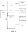
- FIG. 3 a block diagram of an embodiment of system 300 is shown including inner shaft 102 and outer shaft 104 coupled between engine 302 and gear box 304.
- shaft 102 can be coupled to engine 302 by flange 124.
- Outer shaft 104 is configured in gear box 304 to drive various components such as starter 306, hydraulic pump 308, alternating current (“A/C") generator 310 , and direct current (“D/C”) generator 312.
- starter 306 may provide power through gear box 304 to start engine 302.
- gear box 304 can be coupled to gear box 304.
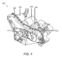
- FIGs. 1 and 4 a diagram of an embodiment of system 400 is shown with PTO 100 installed in Airframe Mounted Accessory Drive (AMAD) gear box 402.
- Gear box 402 is configured to drive D/C generator 404, A/C generator 406, starter 408 and hydraulic pump 410 .
- Flange 124 may be coupled to a flange on the engine (not shown).
- PTO 100 often experiences adhesive wear that prevents shaft axial movement, increasing stresses in PTO 100 . The wear results in the inner shaft 102 having to be discarded and replaced during phase inspections.
- the outer shaft 104 also wears beyond limits resulting in the gear box 402 being removed from the aircraft and returned to the vendor prior to its normal life cycle. The premature wear poses a significant cost and maintenance issue with some aircraft programs.
- sleeve 108 helps prevent the gear box 402 from having to be removed from the aircraft and returned to the vendor for repair prior to completing its full life cycle.
- Sleeve 108 also helps prevent having to discard the inner shaft 102 at each inspection. Note that existing shafts 102 can be retrofitted with notch 110 , thereby extending the life of PTOs 100 currently in service.
Landscapes
- Engineering & Computer Science (AREA)
- General Engineering & Computer Science (AREA)
- Mechanical Engineering (AREA)
- Ocean & Marine Engineering (AREA)
- General Details Of Gearings (AREA)
- Sliding-Contact Bearings (AREA)
- Shafts, Cranks, Connecting Bars, And Related Bearings (AREA)
- Arrangement And Driving Of Transmission Devices (AREA)
Applications Claiming Priority (1)
| Application Number | Priority Date | Filing Date | Title |
|---|---|---|---|
| US12/128,243 US8156831B2 (en) | 2008-05-28 | 2008-05-28 | Apparatus, method and system for reducing adhesive wear on a power take-off shaft |
Publications (3)
| Publication Number | Publication Date |
|---|---|
| EP2128463A2 true EP2128463A2 (fr) | 2009-12-02 |
| EP2128463A3 EP2128463A3 (fr) | 2011-12-21 |
| EP2128463B1 EP2128463B1 (fr) | 2015-12-02 |
Family
ID=41012688
Family Applications (1)
| Application Number | Title | Priority Date | Filing Date |
|---|---|---|---|
| EP09160814.1A Active EP2128463B1 (fr) | 2008-05-28 | 2009-05-20 | Appareil pour réduire l'usure d'adhérence sur un arbre de prise de force |
Country Status (3)
| Country | Link |
|---|---|
| US (2) | US8156831B2 (fr) |
| EP (1) | EP2128463B1 (fr) |
| CA (1) | CA2662540C (fr) |
Families Citing this family (5)
| Publication number | Priority date | Publication date | Assignee | Title |
|---|---|---|---|---|
| US8156831B2 (en) * | 2008-05-28 | 2012-04-17 | Lockheed Martin Corporation | Apparatus, method and system for reducing adhesive wear on a power take-off shaft |
| DE102011002904B4 (de) * | 2011-01-20 | 2022-08-18 | Zf Friedrichshafen Ag | Anordnung eines Getriebes und eines Anbaumoduls |
| CN106764366A (zh) * | 2017-01-13 | 2017-05-31 | 南昌工程学院 | 一种风力发电机润滑油加注、抽排装置 |
| WO2020191128A1 (fr) * | 2019-03-19 | 2020-09-24 | CK Industries, LLC | Protecteur de coupleur de prise de force |
| CN115199928A (zh) * | 2022-07-28 | 2022-10-18 | 哈电发电设备国家工程研究中心有限公司 | 一种矿用自卸车电动轮油箱润滑油的回油装置 |
Citations (1)
| Publication number | Priority date | Publication date | Assignee | Title |
|---|---|---|---|---|
| US3754411A (en) | 1971-04-16 | 1973-08-28 | Glaenzer Spicer Sa | Telescoping drive or propeller shafts |
Family Cites Families (15)
| Publication number | Priority date | Publication date | Assignee | Title |
|---|---|---|---|---|
| GB705022A (en) * | 1951-07-31 | 1954-03-03 | Morgan Crucible Co | Shafts, spindles and the like |
| US2998397A (en) * | 1955-05-18 | 1961-08-29 | Gen Motors Corp | Bearing element comprising thermoplastic resin and sintered teflon particles |
| US2835540A (en) * | 1957-03-14 | 1958-05-20 | Gen Motors Corp | Guide bearing |
| GB1248437A (en) * | 1968-10-24 | 1971-10-06 | Rolls Royce | Lubrication system |
| LU59110A1 (fr) | 1969-07-16 | 1971-03-25 | ||
| US4381737A (en) * | 1980-11-13 | 1983-05-03 | Turner William H | Rotary valved internal combustion engine |
| DE3883465T2 (de) | 1987-09-03 | 1993-12-23 | Quadion Corp | Dichtungsvorrichtung für Lager. |
| US5119905A (en) * | 1991-10-28 | 1992-06-09 | General Motors Corporation | Accessory drive spline lubrication system for a turbine engine reduction gear box |
| US5275206A (en) * | 1992-03-18 | 1994-01-04 | Teledyne Industries, Inc. | Valve system for beverage filling machines |
| US6082494A (en) * | 1998-06-04 | 2000-07-04 | Pratt & Whitney Canada Inc. | Fluid deflecting and straining system |
| US6098753A (en) * | 1998-06-05 | 2000-08-08 | Pratt & Whitney Canada Corp. | System for delivering pressurized lubricant fluids to an interior of a rotating hollow shaft |
| SE0001448L (sv) | 2000-04-19 | 2001-10-20 | Svenska Kenab Karlshamns Ergon | Teleskoprör och sätt att framställa detta |
| GB2365513A (en) * | 2000-08-04 | 2002-02-20 | Pyrotek Engineering Materials | Refractory components for use in metal producing processes |
| US7065954B2 (en) * | 2004-04-20 | 2006-06-27 | Gustavo Francisco Labala | Turbine, particularly useful for small aircraft |
| US8156831B2 (en) * | 2008-05-28 | 2012-04-17 | Lockheed Martin Corporation | Apparatus, method and system for reducing adhesive wear on a power take-off shaft |
-
2008
- 2008-05-28 US US12/128,243 patent/US8156831B2/en active Active
-
2009
- 2009-04-15 CA CA2662540A patent/CA2662540C/fr active Active
- 2009-05-20 EP EP09160814.1A patent/EP2128463B1/fr active Active
-
2012
- 2012-03-15 US US13/421,777 patent/US8960029B2/en active Active
Patent Citations (1)
| Publication number | Priority date | Publication date | Assignee | Title |
|---|---|---|---|---|
| US3754411A (en) | 1971-04-16 | 1973-08-28 | Glaenzer Spicer Sa | Telescoping drive or propeller shafts |
Also Published As
| Publication number | Publication date |
|---|---|
| US8156831B2 (en) | 2012-04-17 |
| US20090293652A1 (en) | 2009-12-03 |
| EP2128463A3 (fr) | 2011-12-21 |
| CA2662540C (fr) | 2016-11-15 |
| EP2128463B1 (fr) | 2015-12-02 |
| CA2662540A1 (fr) | 2009-11-28 |
| US20120227539A1 (en) | 2012-09-13 |
| US8960029B2 (en) | 2015-02-24 |
Similar Documents
| Publication | Publication Date | Title |
|---|---|---|
| US11137060B2 (en) | Electric drive unit cooling and lubrication system with bearing shims and rotor shaft channel | |
| EP2128463B1 (fr) | Appareil pour réduire l'usure d'adhérence sur un arbre de prise de force | |
| JP5346126B2 (ja) | 高速ギア連結器 | |
| CN103703230B (zh) | 包括解耦装置的燃气涡轮机附件传递齿轮箱 | |
| EP3343071B1 (fr) | Support de roues planétaires pour engrenage planétaire | |
| DE102012008652A1 (de) | Getriebemotor und Welle | |
| US8613609B2 (en) | Bi-metal pump gear | |
| US20100231098A1 (en) | Electric machine comprising an elastic connection to a gearbox primary shaft | |
| CN106949138A (zh) | 可伸缩传动轴 | |
| US8408376B2 (en) | Drive uncoupler | |
| CN114270061A (zh) | 滑动轴承 | |
| US8789657B2 (en) | Centrifugal lubricating apparatus | |
| US11781603B2 (en) | Cone clutch system | |
| US20160215855A1 (en) | Aircraft electric drive train with damping/compliance device | |
| EP1454784A2 (fr) | Pignon de différentiel à trou rainuré | |
| CN206830632U (zh) | 可伸缩传动轴 | |
| US12297864B2 (en) | Self lubricating linear guide bushings for reciprocating canning and bottling machinery | |
| CN113864321B (zh) | 一种润滑性能良好的轴向大伸缩鼓型齿联轴器 | |
| CN218151968U (zh) | 一种新型耐磨的农业机械齿轮轴 | |
| US11603890B2 (en) | Driveline engagement system | |
| US11703091B2 (en) | Cone clutch system | |
| CN116006584A (zh) | 磨损能够完全自动补偿的长寿命航空轴承 | |
| Tozaki et al. | Tribological Technology for High Efficient Centrifugal Chiller | |
| DE102012210436A1 (de) | Anfahrelement | |
| Keith Jr et al. | Experimental Evaluation of Journal Bearing Stability and New Gas Bearing Material |
Legal Events
| Date | Code | Title | Description |
|---|---|---|---|
| PUAI | Public reference made under article 153(3) epc to a published international application that has entered the european phase |
Free format text: ORIGINAL CODE: 0009012 |
|
| AK | Designated contracting states |
Kind code of ref document: A2 Designated state(s): AT BE BG CH CY CZ DE DK EE ES FI FR GB GR HR HU IE IS IT LI LT LU LV MC MK MT NL NO PL PT RO SE SI SK TR |
|
| RIC1 | Information provided on ipc code assigned before grant |
Ipc: F16D 3/06 20060101ALI20110701BHEP Ipc: F16C 3/03 20060101AFI20110701BHEP |
|
| PUAL | Search report despatched |
Free format text: ORIGINAL CODE: 0009013 |
|
| AK | Designated contracting states |
Kind code of ref document: A3 Designated state(s): AT BE BG CH CY CZ DE DK EE ES FI FR GB GR HR HU IE IS IT LI LT LU LV MC MK MT NL NO PL PT RO SE SI SK TR |
|
| AX | Request for extension of the european patent |
Extension state: AL BA RS |
|
| RIC1 | Information provided on ipc code assigned before grant |
Ipc: F16D 3/06 20060101ALI20111118BHEP Ipc: F16C 3/03 20060101AFI20111118BHEP |
|
| 17P | Request for examination filed |
Effective date: 20120425 |
|
| GRAP | Despatch of communication of intention to grant a patent |
Free format text: ORIGINAL CODE: EPIDOSNIGR1 |
|
| INTG | Intention to grant announced |
Effective date: 20150526 |
|
| GRAS | Grant fee paid |
Free format text: ORIGINAL CODE: EPIDOSNIGR3 |
|
| GRAA | (expected) grant |
Free format text: ORIGINAL CODE: 0009210 |
|
| AK | Designated contracting states |
Kind code of ref document: B1 Designated state(s): AT BE BG CH CY CZ DE DK EE ES FI FR GB GR HR HU IE IS IT LI LT LU LV MC MK MT NL NO PL PT RO SE SI SK TR |
|
| REG | Reference to a national code |
Ref country code: GB Ref legal event code: FG4D |
|
| REG | Reference to a national code |
Ref country code: AT Ref legal event code: REF Ref document number: 763776 Country of ref document: AT Kind code of ref document: T Effective date: 20151215 Ref country code: CH Ref legal event code: EP |
|
| REG | Reference to a national code |
Ref country code: IE Ref legal event code: FG4D |
|
| REG | Reference to a national code |
Ref country code: DE Ref legal event code: R096 Ref document number: 602009035063 Country of ref document: DE |
|
| REG | Reference to a national code |
Ref country code: NL Ref legal event code: MP Effective date: 20160302 |
|
| REG | Reference to a national code |
Ref country code: LT Ref legal event code: MG4D |
|
| REG | Reference to a national code |
Ref country code: AT Ref legal event code: MK05 Ref document number: 763776 Country of ref document: AT Kind code of ref document: T Effective date: 20151202 |
|
| PG25 | Lapsed in a contracting state [announced via postgrant information from national office to epo] |
Ref country code: HR Free format text: LAPSE BECAUSE OF FAILURE TO SUBMIT A TRANSLATION OF THE DESCRIPTION OR TO PAY THE FEE WITHIN THE PRESCRIBED TIME-LIMIT Effective date: 20151202 Ref country code: LT Free format text: LAPSE BECAUSE OF FAILURE TO SUBMIT A TRANSLATION OF THE DESCRIPTION OR TO PAY THE FEE WITHIN THE PRESCRIBED TIME-LIMIT Effective date: 20151202 Ref country code: NO Free format text: LAPSE BECAUSE OF FAILURE TO SUBMIT A TRANSLATION OF THE DESCRIPTION OR TO PAY THE FEE WITHIN THE PRESCRIBED TIME-LIMIT Effective date: 20160302 Ref country code: ES Free format text: LAPSE BECAUSE OF FAILURE TO SUBMIT A TRANSLATION OF THE DESCRIPTION OR TO PAY THE FEE WITHIN THE PRESCRIBED TIME-LIMIT Effective date: 20151202 |
|
| REG | Reference to a national code |
Ref country code: DE Ref legal event code: R082 Ref document number: 602009035063 Country of ref document: DE Representative=s name: HERNANDEZ, YORCK, DIPL.-ING., DE |
|
| REG | Reference to a national code |
Ref country code: FR Ref legal event code: PLFP Year of fee payment: 8 |
|
| PG25 | Lapsed in a contracting state [announced via postgrant information from national office to epo] |
Ref country code: PL Free format text: LAPSE BECAUSE OF FAILURE TO SUBMIT A TRANSLATION OF THE DESCRIPTION OR TO PAY THE FEE WITHIN THE PRESCRIBED TIME-LIMIT Effective date: 20151202 Ref country code: NL Free format text: LAPSE BECAUSE OF FAILURE TO SUBMIT A TRANSLATION OF THE DESCRIPTION OR TO PAY THE FEE WITHIN THE PRESCRIBED TIME-LIMIT Effective date: 20151202 Ref country code: LV Free format text: LAPSE BECAUSE OF FAILURE TO SUBMIT A TRANSLATION OF THE DESCRIPTION OR TO PAY THE FEE WITHIN THE PRESCRIBED TIME-LIMIT Effective date: 20151202 Ref country code: SE Free format text: LAPSE BECAUSE OF FAILURE TO SUBMIT A TRANSLATION OF THE DESCRIPTION OR TO PAY THE FEE WITHIN THE PRESCRIBED TIME-LIMIT Effective date: 20151202 Ref country code: GR Free format text: LAPSE BECAUSE OF FAILURE TO SUBMIT A TRANSLATION OF THE DESCRIPTION OR TO PAY THE FEE WITHIN THE PRESCRIBED TIME-LIMIT Effective date: 20160303 Ref country code: FI Free format text: LAPSE BECAUSE OF FAILURE TO SUBMIT A TRANSLATION OF THE DESCRIPTION OR TO PAY THE FEE WITHIN THE PRESCRIBED TIME-LIMIT Effective date: 20151202 Ref country code: AT Free format text: LAPSE BECAUSE OF FAILURE TO SUBMIT A TRANSLATION OF THE DESCRIPTION OR TO PAY THE FEE WITHIN THE PRESCRIBED TIME-LIMIT Effective date: 20151202 |
|
| PG25 | Lapsed in a contracting state [announced via postgrant information from national office to epo] |
Ref country code: IS Free format text: LAPSE BECAUSE OF FAILURE TO SUBMIT A TRANSLATION OF THE DESCRIPTION OR TO PAY THE FEE WITHIN THE PRESCRIBED TIME-LIMIT Effective date: 20151202 |
|
| PG25 | Lapsed in a contracting state [announced via postgrant information from national office to epo] |
Ref country code: CZ Free format text: LAPSE BECAUSE OF FAILURE TO SUBMIT A TRANSLATION OF THE DESCRIPTION OR TO PAY THE FEE WITHIN THE PRESCRIBED TIME-LIMIT Effective date: 20151202 |
|
| PG25 | Lapsed in a contracting state [announced via postgrant information from national office to epo] |
Ref country code: SK Free format text: LAPSE BECAUSE OF FAILURE TO SUBMIT A TRANSLATION OF THE DESCRIPTION OR TO PAY THE FEE WITHIN THE PRESCRIBED TIME-LIMIT Effective date: 20151202 Ref country code: EE Free format text: LAPSE BECAUSE OF FAILURE TO SUBMIT A TRANSLATION OF THE DESCRIPTION OR TO PAY THE FEE WITHIN THE PRESCRIBED TIME-LIMIT Effective date: 20151202 Ref country code: IS Free format text: LAPSE BECAUSE OF FAILURE TO SUBMIT A TRANSLATION OF THE DESCRIPTION OR TO PAY THE FEE WITHIN THE PRESCRIBED TIME-LIMIT Effective date: 20160402 Ref country code: RO Free format text: LAPSE BECAUSE OF FAILURE TO SUBMIT A TRANSLATION OF THE DESCRIPTION OR TO PAY THE FEE WITHIN THE PRESCRIBED TIME-LIMIT Effective date: 20151202 Ref country code: BE Free format text: LAPSE BECAUSE OF NON-PAYMENT OF DUE FEES Effective date: 20160531 Ref country code: PT Free format text: LAPSE BECAUSE OF FAILURE TO SUBMIT A TRANSLATION OF THE DESCRIPTION OR TO PAY THE FEE WITHIN THE PRESCRIBED TIME-LIMIT Effective date: 20160404 |
|
| REG | Reference to a national code |
Ref country code: DE Ref legal event code: R097 Ref document number: 602009035063 Country of ref document: DE |
|
| PLBE | No opposition filed within time limit |
Free format text: ORIGINAL CODE: 0009261 |
|
| STAA | Information on the status of an ep patent application or granted ep patent |
Free format text: STATUS: NO OPPOSITION FILED WITHIN TIME LIMIT |
|
| PG25 | Lapsed in a contracting state [announced via postgrant information from national office to epo] |
Ref country code: DK Free format text: LAPSE BECAUSE OF FAILURE TO SUBMIT A TRANSLATION OF THE DESCRIPTION OR TO PAY THE FEE WITHIN THE PRESCRIBED TIME-LIMIT Effective date: 20151202 |
|
| 26N | No opposition filed |
Effective date: 20160905 |
|
| PG25 | Lapsed in a contracting state [announced via postgrant information from national office to epo] |
Ref country code: SI Free format text: LAPSE BECAUSE OF FAILURE TO SUBMIT A TRANSLATION OF THE DESCRIPTION OR TO PAY THE FEE WITHIN THE PRESCRIBED TIME-LIMIT Effective date: 20151202 |
|
| PG25 | Lapsed in a contracting state [announced via postgrant information from national office to epo] |
Ref country code: LU Free format text: LAPSE BECAUSE OF FAILURE TO SUBMIT A TRANSLATION OF THE DESCRIPTION OR TO PAY THE FEE WITHIN THE PRESCRIBED TIME-LIMIT Effective date: 20160520 Ref country code: BE Free format text: LAPSE BECAUSE OF FAILURE TO SUBMIT A TRANSLATION OF THE DESCRIPTION OR TO PAY THE FEE WITHIN THE PRESCRIBED TIME-LIMIT Effective date: 20151202 |
|
| REG | Reference to a national code |
Ref country code: CH Ref legal event code: PL |
|
| PG25 | Lapsed in a contracting state [announced via postgrant information from national office to epo] |
Ref country code: CH Free format text: LAPSE BECAUSE OF NON-PAYMENT OF DUE FEES Effective date: 20160531 Ref country code: LI Free format text: LAPSE BECAUSE OF NON-PAYMENT OF DUE FEES Effective date: 20160531 |
|
| REG | Reference to a national code |
Ref country code: IE Ref legal event code: MM4A |
|
| REG | Reference to a national code |
Ref country code: FR Ref legal event code: PLFP Year of fee payment: 9 |
|
| PG25 | Lapsed in a contracting state [announced via postgrant information from national office to epo] |
Ref country code: IE Free format text: LAPSE BECAUSE OF NON-PAYMENT OF DUE FEES Effective date: 20160520 |
|
| REG | Reference to a national code |
Ref country code: FR Ref legal event code: PLFP Year of fee payment: 10 |
|
| PG25 | Lapsed in a contracting state [announced via postgrant information from national office to epo] |
Ref country code: HU Free format text: LAPSE BECAUSE OF FAILURE TO SUBMIT A TRANSLATION OF THE DESCRIPTION OR TO PAY THE FEE WITHIN THE PRESCRIBED TIME-LIMIT; INVALID AB INITIO Effective date: 20090520 Ref country code: CY Free format text: LAPSE BECAUSE OF FAILURE TO SUBMIT A TRANSLATION OF THE DESCRIPTION OR TO PAY THE FEE WITHIN THE PRESCRIBED TIME-LIMIT Effective date: 20151202 |
|
| PG25 | Lapsed in a contracting state [announced via postgrant information from national office to epo] |
Ref country code: MC Free format text: LAPSE BECAUSE OF FAILURE TO SUBMIT A TRANSLATION OF THE DESCRIPTION OR TO PAY THE FEE WITHIN THE PRESCRIBED TIME-LIMIT Effective date: 20151202 Ref country code: MT Free format text: LAPSE BECAUSE OF NON-PAYMENT OF DUE FEES Effective date: 20160531 Ref country code: TR Free format text: LAPSE BECAUSE OF FAILURE TO SUBMIT A TRANSLATION OF THE DESCRIPTION OR TO PAY THE FEE WITHIN THE PRESCRIBED TIME-LIMIT Effective date: 20151202 Ref country code: MK Free format text: LAPSE BECAUSE OF FAILURE TO SUBMIT A TRANSLATION OF THE DESCRIPTION OR TO PAY THE FEE WITHIN THE PRESCRIBED TIME-LIMIT Effective date: 20151202 |
|
| PG25 | Lapsed in a contracting state [announced via postgrant information from national office to epo] |
Ref country code: BG Free format text: LAPSE BECAUSE OF FAILURE TO SUBMIT A TRANSLATION OF THE DESCRIPTION OR TO PAY THE FEE WITHIN THE PRESCRIBED TIME-LIMIT Effective date: 20151202 |
|
| PGFP | Annual fee paid to national office [announced via postgrant information from national office to epo] |
Ref country code: DE Payment date: 20250529 Year of fee payment: 17 |
|
| PGFP | Annual fee paid to national office [announced via postgrant information from national office to epo] |
Ref country code: IT Payment date: 20250521 Year of fee payment: 17 |
|
| PGFP | Annual fee paid to national office [announced via postgrant information from national office to epo] |
Ref country code: FR Payment date: 20250526 Year of fee payment: 17 |
|
| PGFP | Annual fee paid to national office [announced via postgrant information from national office to epo] |
Ref country code: GB Payment date: 20260327 Year of fee payment: 18 |