EP2128482B1 - Amortisseur d'oscillations doté d'une force d'amortissement dépendant de l'amplitude - Google Patents
Amortisseur d'oscillations doté d'une force d'amortissement dépendant de l'amplitude Download PDFInfo
- Publication number
- EP2128482B1 EP2128482B1 EP09006872A EP09006872A EP2128482B1 EP 2128482 B1 EP2128482 B1 EP 2128482B1 EP 09006872 A EP09006872 A EP 09006872A EP 09006872 A EP09006872 A EP 09006872A EP 2128482 B1 EP2128482 B1 EP 2128482B1
- Authority
- EP
- European Patent Office
- Prior art keywords
- piston
- housing
- vibration damper
- damper according
- piston rod
- Prior art date
- Legal status (The legal status is an assumption and is not a legal conclusion. Google has not performed a legal analysis and makes no representation as to the accuracy of the status listed.)
- Not-in-force
Links
- 238000013016 damping Methods 0.000 title claims description 43
- 230000001419 dependent effect Effects 0.000 title claims description 6
- 238000006073 displacement reaction Methods 0.000 claims description 3
- 238000005253 cladding Methods 0.000 abstract 1
- 238000010276 construction Methods 0.000 description 3
- 238000003780 insertion Methods 0.000 description 2
- 230000037431 insertion Effects 0.000 description 2
- 230000002238 attenuated effect Effects 0.000 description 1
- 230000007423 decrease Effects 0.000 description 1
- 230000000694 effects Effects 0.000 description 1
- 239000000725 suspension Substances 0.000 description 1
- 230000001360 synchronised effect Effects 0.000 description 1
Images

Classifications
-
- F—MECHANICAL ENGINEERING; LIGHTING; HEATING; WEAPONS; BLASTING
- F16—ENGINEERING ELEMENTS AND UNITS; GENERAL MEASURES FOR PRODUCING AND MAINTAINING EFFECTIVE FUNCTIONING OF MACHINES OR INSTALLATIONS; THERMAL INSULATION IN GENERAL
- F16F—SPRINGS; SHOCK-ABSORBERS; MEANS FOR DAMPING VIBRATION
- F16F9/00—Springs, vibration-dampers, shock-absorbers, or similarly-constructed movement-dampers using a fluid or the equivalent as damping medium
- F16F9/32—Details
- F16F9/50—Special means providing automatic damping adjustment, i.e. self-adjustment of damping by particular sliding movements of a valve element, other than flexions or displacement of valve discs; Special means providing self-adjustment of spring characteristics
- F16F9/512—Means responsive to load action, i.e. static load on the damper or dynamic fluid pressure changes in the damper, e.g. due to changes in velocity
- F16F9/5126—Piston, or piston-like valve elements
-
- F—MECHANICAL ENGINEERING; LIGHTING; HEATING; WEAPONS; BLASTING
- F16—ENGINEERING ELEMENTS AND UNITS; GENERAL MEASURES FOR PRODUCING AND MAINTAINING EFFECTIVE FUNCTIONING OF MACHINES OR INSTALLATIONS; THERMAL INSULATION IN GENERAL
- F16F—SPRINGS; SHOCK-ABSORBERS; MEANS FOR DAMPING VIBRATION
- F16F9/00—Springs, vibration-dampers, shock-absorbers, or similarly-constructed movement-dampers using a fluid or the equivalent as damping medium
- F16F9/32—Details
- F16F9/3207—Constructional features
- F16F9/3228—Constructional features of connections between pistons and piston rods
Definitions
- the invention relates to a vibration damper with amplitude-dependent damping force according to the preamble of patent claim 1.
- a sleeve-shaped piston is mounted axially movable to a piston rod.
- a double-acting stop for attached to the piston.
- only a small space for valve discs is available.
- a similar variant is from the DE 828 201 known, the piston valve has obviously only one valve disc for the damping of a piston rod retraction movement.
- the object of the present invention is to realize a vibration damper with amplitude-dependent damping force, in which an axially movable piston valve is used and a very easy adaptability to a conventional vibration damper is possible.
- the object is achieved in that the piston rod is designed in two parts and the piston is fixed to a first piston rod portion, the other end is movable in a housing on a second piston rod portion between two abutment surfaces.
- the big advantage of the invention is that a conventional piston with valve disk assembly can be used.
- the vibration damper can be very well matched to a particular driving behavior without structural conditions are a hindrance, z. B. by too small valve disks or passage cross-sections to the valve disks, so that in turn a soft response would be hardly feasible.
- the axial piston movement is specifically attenuated by the first piston rod portion carries a separating piston, which forms a throttle valve with at least one connecting channel in the housing wall.
- At least one working chamber of the housing has an opening in the inflow into the working chamber check valve.
- the housing has a separate cover, in the end face of the check valve is arranged.
- the bypass is formed by a very simple axial groove in the outer wall of the housing.
- a piston with valve disks is arranged on both piston rod sections.
- Such a vibration damper always generates a basic damping force, which increases in amplitude.
- the housing has an annular working chamber and a fully cylindrical working chamber whose volume is determined by the diameter of the separating piston. To compensate for the volume of the two working chambers at least one working chamber is connected via a compensation channel in a piston rod portion with one of the working spaces.
- connection channels of the working chambers of the compensation channel With regard to a free dimensioning of the connection channels of the working chambers of the compensation channel is released path-dependent. If the connection channels are to act, the compensation channel is switched off.
- the compensation channel has a radial opening which forms a slide valve with a cover of the housing.
- This slide valve function is inevitably a functional circuit of the slide valve ge instantlyrleitstet.
- connection channel between the two working chambers.
- This connection channel additionally serves for volume exchange between the working chambers.
- connection channel is formed by a groove in the housing.
- the connecting channel has a shorter axial extent than the distance between the two connection channels of the working chambers. This ensures that the Movement of the separating piston in the direction of its end positions is particularly effectively damped by the throttle valves formed by the connection channels.
- the separating piston can be equipped, at least for a relative direction of movement to the housing, with a damping valve, so that a further displacement force increase for the separating piston relative to the housing is achieved.
- the FIG. 1 shows a vibration damper 1 in two-pipe design, where you can apply the invention in any other types.
- the vibration damper 1 comprises a cylinder 3 which is delimited at the end by a bottom valve 5 and a piston rod guide 7.
- a two-part piston rod 9 is arranged axially movable.
- the piston rod comprises a first portion 9a, on which a piston 11 with damping valves 13; 15 is fixed for both directions of movement of the piston 11, wherein the damping valves of valve disks 17; 19 in cooperation with passageways 21; 23 are formed.
- the piston 11 divides the cylinder into a completely with damping medium the piston rod 11 opposite end of the first piston rod portion 9a carries a separating piston 29 which in a housing 31 at a second piston rod portion 9b between two stop surfaces 33; 35 of the housing 31 is axially movable.
- the separating piston 29 divides the housing 31 into two working chambers 41; 43, wherein in each case at least one connection channel 37; 39 opens into a working chamber.
- Both working chambers 41; 43 have a non-return valve 45 opening into the working chambers in the inflow direction; 47 on.
- the check valve 45 comprises an axially movable switching ring 49, which allows an inflow of a gap 51 between the piston 11 and the housing 31 with the working chamber 43.
- the non-return valve 41 is arranged in its end face and has a valve disk 55 which is biased in the closing direction by a spring element 57.
- the bypass 59 Radially outside the working chambers 41; 43 in the housing 31 is at least one bypass 59 between the piston rod side working space 25 and the Gap between the housing 31 and the piston 11 in front.
- the bypass 59 is formed by an axial groove in the outer wall of the housing 31.
- the piston 11 Based on the illustrated center position of the separating piston 29, the piston 11 retains its instantaneous position within the cylinder 3 during a retraction movement of the second piston rod section 9b, whereby the separating piston 29, however, executes a displacement movement in the housing 31 in the direction of the stop surface 35.
- the piston rod-side working space 25 increases and the intermediate space 51 decreases. Damping medium from the working chamber 41 of the housing can flow in through the connecting channel 39 into the piston rod-side working space 25. Damping medium from the intermediate space can also flow via the connecting channel 37 into the enlarged working chamber 43 and also via the bypass 59 into the piston rod-side working space 25.
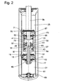
- FIG. 2 An essential addition to the Fig. 1 is that on both the piston rod portion 9a as well as on the piston rod portion 9b, a piston 11; 67 with valve disks 17; 19, 69; 71 are arranged so that for both directions of movement of the piston rod sections 9a; 9b damping valves 13; 15; 73; 75 are available. This results in a basic damping with each movement of the piston rod portion 9b.
- the separating piston 29 is for at least one direction of relative movement to the housing 31 with a damping valve 77; 79 equipped.
- the separating piston 29 can Damping medium from the respective compressed working chamber 41; 43 through one of the damping valves 77; 79 are displaced.
- an additional damping of the separating piston movement and thus the relative movement between the piston rod sections 9a; 9b reached.
- With the additional damping in the separating piston 29 and an external damping force is achieved.
- FIG. 1 Another measure compared to Fig. 1 consists in that via a connecting channel 81 between the two working chambers 41; 43, the action of the separating piston 29 can be bridged.
- the connecting channel 81 is formed by a groove in the housing inner wall, wherein the length of the connecting channel is shorter than the distance between the two connecting channels 37; 39th
- the working chambers 41; 43 in the housing 31 vary in volume in a separating piston movement differently.
- the volume change of the working chamber 43 is determined by the housing inner diameter and the outer diameter of the piston rod portion 9a. Notwithstanding this, the volume change of the working chamber 41 is calculated exclusively via the housing inner diameter.
- the piston rod section 9a has a compensation channel 83, which connects the working chamber 27 to the working chamber 43 in the housing 31 via a radial opening 85.
- the separating piston 29 As soon as the separating piston 29 has passed the groove 81 and the connecting channel 39, the further separating piston movement is markedly throttled, with the damping valve 85 additionally being used in the separating piston 29. In a further insertion movement of the piston rod portion 9b, the separating piston 29 reaches its upper end position on the cover 53. If the insertion movement continues even further, at the latest the piston 11 engages with the damping valve 19 and moves together with the piston rod portion 9b.
- the separating piston 29 moves away when the piston rod section 9a is stationary.
- the working chamber 41 can be flooded via the check valve 47 without a in the working chamber 41 a Negative pressure can occur. Due to the connection of the two working chambers 41; 43 via the connection channels 37; 39 and / or the groove 81 sets the separating piston 29 on further extension movement of the piston rod portion 9b its relative movement to the housing 31 in the direction of the stop surface 33 continues. The thereby enlarging working chamber 41 damping medium from the working chamber 27 via the compensation channel 83 can be refilled.
Landscapes
- Engineering & Computer Science (AREA)
- General Engineering & Computer Science (AREA)
- Mechanical Engineering (AREA)
- Physics & Mathematics (AREA)
- Fluid Mechanics (AREA)
- Fluid-Damping Devices (AREA)
- Buildings Adapted To Withstand Abnormal External Influences (AREA)
- Golf Clubs (AREA)
Claims (14)
- Amortisseur d'oscillations (1) comprenant un cylindre (3), dans lequel est disposée, de manière déplaçable axialement, une tige de piston (9), un piston (11), qui divise le cylindre (3) rempli de fluide d'amortissement en deux espaces de travail (25 ; 27) étant muni de disques de soupape (17 ; 19) et pouvant effectuer dans certaines limites un mouvement relatif axial par rapport à la tige de piston (9b), et une augmentation de la force d'amortissement se produisant à la fin du mouvement relatif,
caractérisé en ce que
la tige de piston (9) est réalisée en deux parties et le piston (11) est fixé à une première portion de la tige de piston (9a), dont l'autre extrémité est déplaçable dans un boîtier (31) sur une deuxième portion de la tige de piston (9b) entre deux surfaces de butée (33 ; 35). - Amortisseur d'oscillations selon la revendication 1,
caractérisé en ce que
la première portion de tige de piston (9a) porte un piston de séparation (29), qui forme avec au moins un canal de raccordement (37 ; 39) une soupape d'étranglement dans la paroi du boîtier (31). - Amortisseur d'oscillations selon la revendication 1,
caractérisé en ce
qu'au moins une chambre de travail (41 ; 43) du boîtier (31) présente une soupape de non retour (45 ; 47) s'ouvrant dans la direction d'afflux dans la chambre de travail (41 ; 43). - Amortisseur d'oscillations selon la revendication 3,
caractérisé en ce que
le boîtier (31) présente un couvercle séparé (53), dans la surface frontale duquel est disposée la soupape de non retour (47). - Amortisseur d'oscillations selon la revendication 3,
caractérisé en ce
qu'en dehors de l'au moins une chambre de travail (41 ; 43), il existe au moins une dérivation (59) entre l'un des espaces de travail (25) dans le cylindre (3) et un espace intermédiaire (51) entre le boîtier (31) et le piston (11). - Amortisseur d'oscillations selon la revendication 5,
caractérisé en ce que
la dérivation (59) est formée par une rainure axiale dans la paroi extérieure du boîtier (31). - Amortisseur d'oscillations selon la revendication 1,
caractérisé en ce que
l'on dispose sur les deux portions de tige de piston (9a ; 9b) à chaque fois un piston (11 ; 67) avec des disques de soupape (17 ; 19 ; 69 ; 71). - Amortisseur d'oscillations selon la revendication 1,
caractérisé en ce
qu'au moins une chambre de travail (41 ; 43) du boîtier (31) est connectée à l'un des espaces de travail (27) par le biais d'un canal d'équilibrage (83 ; 85) dans une portion de la tige de piston (9a). - Amortisseur d'oscillations selon la revendication 8,
caractérisé en ce que
le canal d'équilibrage (83 ; 85) est libéré en fonction de la course. - Amortisseur d'oscillations selon la revendication 8,
caractérisé en ce que
le canal d'équilibrage (83 ; 85) présente une ouverture radiale (85), qui forme avec un couvercle (87) du boîtier (31) une soupape à tiroir. - Amortisseur d'oscillations selon la revendication 2,
caractérisé en ce que
le piston de séparation (29) divise le boîtier (31) en deux chambres de travail (41 ; 43), un canal de connexion (81) existant entre les deux chambres de travail (41 ; 43). - Amortisseur d'oscillations selon la revendication 11,
caractérisé en ce que
le canal de connexion (81) est formé par une rainure dans le boîtier (31). - Amortisseur d'oscillations selon la revendication 12,
caractérisé en ce que
le canal de connexion (81) présente une étendue axiale plus courte que la distance des deux canaux de raccordement (37 ; 39) des chambres de travail (41 ; 43). - Amortisseur d'oscillations selon la revendication 2,
caractérisé en ce que
le piston de séparation (29) est muni d'une soupape d'amortissement (77 ; 79) au moins pour un sens de déplacement relatif vers le boîtier (31).
Applications Claiming Priority (1)
| Application Number | Priority Date | Filing Date | Title |
|---|---|---|---|
| DE102008002062A DE102008002062B3 (de) | 2008-05-29 | 2008-05-29 | Schwingungsdämpfer mit amplitudenabhängiger Dämpfkraft |
Publications (2)
| Publication Number | Publication Date |
|---|---|
| EP2128482A1 EP2128482A1 (fr) | 2009-12-02 |
| EP2128482B1 true EP2128482B1 (fr) | 2010-09-29 |
Family
ID=40810337
Family Applications (1)
| Application Number | Title | Priority Date | Filing Date |
|---|---|---|---|
| EP09006872A Not-in-force EP2128482B1 (fr) | 2008-05-29 | 2009-05-22 | Amortisseur d'oscillations doté d'une force d'amortissement dépendant de l'amplitude |
Country Status (3)
| Country | Link |
|---|---|
| EP (1) | EP2128482B1 (fr) |
| AT (1) | ATE483119T1 (fr) |
| DE (2) | DE102008002062B3 (fr) |
Families Citing this family (2)
| Publication number | Priority date | Publication date | Assignee | Title |
|---|---|---|---|---|
| GB2498747B (en) | 2012-01-24 | 2018-05-09 | Titus Int Ltd | Improvements in damper assemblies |
| DE102012212684B3 (de) * | 2012-07-19 | 2013-11-28 | Zf Friedrichshafen Ag | Schwingungsdämpfer mit frequenzselektiver Dämpfkraft |
Family Cites Families (7)
| Publication number | Priority date | Publication date | Assignee | Title |
|---|---|---|---|---|
| DE828201C (de) * | 1950-04-25 | 1952-01-17 | Daimler Benz Ag | Fluessigkeits-Stossdaempfer, insbesondere fuer Kraftfahrzeuge |
| DE1264165B (de) * | 1964-10-24 | 1968-03-21 | Deutsche Bundesbahn | Hydraulischer Schwingungsdaempfer |
| DE3134201A1 (de) * | 1981-08-27 | 1983-03-10 | Lothar Ing. Höfer (grad.), 1000 Berlin | Stossdaempfer zur angepassten daempfung von rad- und karosserieschwingungen bei fahrzeugen |
| US4635766A (en) * | 1985-01-14 | 1987-01-13 | Ford Motor Company | Automotive suspension strut with increased stroke |
| DE19738617C2 (de) * | 1997-09-04 | 2003-03-13 | Daimler Chrysler Ag | Stoßdämpfer für Kraftfahrzeuge |
| WO2003081077A1 (fr) * | 2002-03-21 | 2003-10-02 | Julius Blum Gesellschaft M.B.H. | Dispositif de freinage et d'amortissement pneumatique, notamment pour des elements de meuble mobiles |
| DE602006005365D1 (de) * | 2006-09-13 | 2009-04-09 | Horstman Defence Systems Ltd | Aufhängungsvorrichtung |
-
2008
- 2008-05-29 DE DE102008002062A patent/DE102008002062B3/de not_active Expired - Fee Related
-
2009
- 2009-05-22 AT AT09006872T patent/ATE483119T1/de active
- 2009-05-22 EP EP09006872A patent/EP2128482B1/fr not_active Not-in-force
- 2009-05-22 DE DE502009000112T patent/DE502009000112D1/de active Active
Also Published As
| Publication number | Publication date |
|---|---|
| DE502009000112D1 (de) | 2010-11-11 |
| ATE483119T1 (de) | 2010-10-15 |
| EP2128482A1 (fr) | 2009-12-02 |
| DE102008002062B3 (de) | 2009-11-26 |
Similar Documents
| Publication | Publication Date | Title |
|---|---|---|
| EP1832781B1 (fr) | Amortisseur d'oscillations | |
| EP1826454B1 (fr) | Amortisseur d'oscillations doté d'une force d'amortissement à amplitude sélective | |
| EP1152166B1 (fr) | Amortisseur de chocs avec amortissement dépendant de l'amplitude | |
| DE112016004164B4 (de) | Stoßdämpfer | |
| DE112020003042T5 (de) | Stossdämpfer | |
| WO2016131908A1 (fr) | Amortisseur de vibrations réglable | |
| DE102007057574B3 (de) | Feder-Dämpfer-Einheit eines Druckstöße dämpfenden Stoßreduzierelements, insbesondere für Schienenfahrzeuge | |
| DE102004058965B4 (de) | Schwingungsdämpfer mit amplitudenselektiver Dämpfkraft | |
| DE102012212684B3 (de) | Schwingungsdämpfer mit frequenzselektiver Dämpfkraft | |
| WO2017198403A1 (fr) | Amortisseur de vibrations dont la force d'amortissement est fonction de la course | |
| WO2018103982A1 (fr) | Butée de fin de course pour amortisseur de vibrations | |
| EP1923595A2 (fr) | Amortisseur d'oscillations doté d'une force d'amortissement dépendant de l'amplitude | |
| DE102012215614A1 (de) | Schwingungsdämpfer mit einer beschleunigungsabhängigen Dämpfeinrichtung | |
| WO2016206885A1 (fr) | Ensemble soupapes d'amortissement | |
| EP2374638A2 (fr) | Jambe de force dotée d'une fonction de réglage de niveau | |
| EP2128482B1 (fr) | Amortisseur d'oscillations doté d'une force d'amortissement dépendant de l'amplitude | |
| DE102008014543B3 (de) | Schwingungsdämpfer mit amplitudenselektiver Dämpfkraft | |
| DE102016225767A1 (de) | Dämpfventil | |
| DE102005009762A1 (de) | Schwingungsdämpfer mit hydraulischem Endanschlag | |
| DE102010031144B4 (de) | Schwingungsdämpfer mit amplitudenabhängiger Dämpfkraft | |
| DE102019212964A1 (de) | Schwingungsdämpfer mit einer Zusatzdämpfung | |
| DE4025255A1 (de) | Kolbenzylinderanordnung mit den zylinder umschliessendem ausgleichsraum | |
| EP2191165B1 (fr) | Amortisseur de vibrations à force dépendant de l'amplitude | |
| DE102008009543B3 (de) | Schwingungsdämpfer mit amplitudenabhängiger Dämpfkraft | |
| DE102021114814B4 (de) | Linear-Aktuator |
Legal Events
| Date | Code | Title | Description |
|---|---|---|---|
| PUAI | Public reference made under article 153(3) epc to a published international application that has entered the european phase |
Free format text: ORIGINAL CODE: 0009012 |
|
| AK | Designated contracting states |
Kind code of ref document: A1 Designated state(s): AT BE BG CH CY CZ DE DK EE ES FI FR GB GR HR HU IE IS IT LI LT LU LV MC MK MT NL NO PL PT RO SE SI SK TR |
|
| 17P | Request for examination filed |
Effective date: 20091202 |
|
| GRAP | Despatch of communication of intention to grant a patent |
Free format text: ORIGINAL CODE: EPIDOSNIGR1 |
|
| GRAS | Grant fee paid |
Free format text: ORIGINAL CODE: EPIDOSNIGR3 |
|
| GRAA | (expected) grant |
Free format text: ORIGINAL CODE: 0009210 |
|
| AK | Designated contracting states |
Kind code of ref document: B1 Designated state(s): AT BE BG CH CY CZ DE DK EE ES FI FR GB GR HR HU IE IS IT LI LT LU LV MC MK MT NL NO PL PT RO SE SI SK TR |
|
| REG | Reference to a national code |
Ref country code: GB Ref legal event code: FG4D Free format text: NOT ENGLISH |
|
| REG | Reference to a national code |
Ref country code: CH Ref legal event code: EP |
|
| REG | Reference to a national code |
Ref country code: IE Ref legal event code: FG4D Free format text: LANGUAGE OF EP DOCUMENT: GERMAN |
|
| REF | Corresponds to: |
Ref document number: 502009000112 Country of ref document: DE Date of ref document: 20101111 Kind code of ref document: P |
|
| PG25 | Lapsed in a contracting state [announced via postgrant information from national office to epo] |
Ref country code: FI Free format text: LAPSE BECAUSE OF FAILURE TO SUBMIT A TRANSLATION OF THE DESCRIPTION OR TO PAY THE FEE WITHIN THE PRESCRIBED TIME-LIMIT Effective date: 20100929 Ref country code: NO Free format text: LAPSE BECAUSE OF FAILURE TO SUBMIT A TRANSLATION OF THE DESCRIPTION OR TO PAY THE FEE WITHIN THE PRESCRIBED TIME-LIMIT Effective date: 20101229 Ref country code: LT Free format text: LAPSE BECAUSE OF FAILURE TO SUBMIT A TRANSLATION OF THE DESCRIPTION OR TO PAY THE FEE WITHIN THE PRESCRIBED TIME-LIMIT Effective date: 20100929 |
|
| REG | Reference to a national code |
Ref country code: NL Ref legal event code: VDEP Effective date: 20100929 |
|
| LTIE | Lt: invalidation of european patent or patent extension |
Effective date: 20100929 |
|
| PG25 | Lapsed in a contracting state [announced via postgrant information from national office to epo] |
Ref country code: SI Free format text: LAPSE BECAUSE OF FAILURE TO SUBMIT A TRANSLATION OF THE DESCRIPTION OR TO PAY THE FEE WITHIN THE PRESCRIBED TIME-LIMIT Effective date: 20100929 Ref country code: HR Free format text: LAPSE BECAUSE OF FAILURE TO SUBMIT A TRANSLATION OF THE DESCRIPTION OR TO PAY THE FEE WITHIN THE PRESCRIBED TIME-LIMIT Effective date: 20100929 |
|
| PG25 | Lapsed in a contracting state [announced via postgrant information from national office to epo] |
Ref country code: LV Free format text: LAPSE BECAUSE OF FAILURE TO SUBMIT A TRANSLATION OF THE DESCRIPTION OR TO PAY THE FEE WITHIN THE PRESCRIBED TIME-LIMIT Effective date: 20100929 Ref country code: GR Free format text: LAPSE BECAUSE OF FAILURE TO SUBMIT A TRANSLATION OF THE DESCRIPTION OR TO PAY THE FEE WITHIN THE PRESCRIBED TIME-LIMIT Effective date: 20101230 Ref country code: SE Free format text: LAPSE BECAUSE OF FAILURE TO SUBMIT A TRANSLATION OF THE DESCRIPTION OR TO PAY THE FEE WITHIN THE PRESCRIBED TIME-LIMIT Effective date: 20100929 |
|
| REG | Reference to a national code |
Ref country code: IE Ref legal event code: FD4D |
|
| PG25 | Lapsed in a contracting state [announced via postgrant information from national office to epo] |
Ref country code: EE Free format text: LAPSE BECAUSE OF FAILURE TO SUBMIT A TRANSLATION OF THE DESCRIPTION OR TO PAY THE FEE WITHIN THE PRESCRIBED TIME-LIMIT Effective date: 20100929 Ref country code: RO Free format text: LAPSE BECAUSE OF FAILURE TO SUBMIT A TRANSLATION OF THE DESCRIPTION OR TO PAY THE FEE WITHIN THE PRESCRIBED TIME-LIMIT Effective date: 20100929 Ref country code: CZ Free format text: LAPSE BECAUSE OF FAILURE TO SUBMIT A TRANSLATION OF THE DESCRIPTION OR TO PAY THE FEE WITHIN THE PRESCRIBED TIME-LIMIT Effective date: 20100929 Ref country code: IT Free format text: LAPSE BECAUSE OF FAILURE TO SUBMIT A TRANSLATION OF THE DESCRIPTION OR TO PAY THE FEE WITHIN THE PRESCRIBED TIME-LIMIT Effective date: 20100929 Ref country code: PT Free format text: LAPSE BECAUSE OF FAILURE TO SUBMIT A TRANSLATION OF THE DESCRIPTION OR TO PAY THE FEE WITHIN THE PRESCRIBED TIME-LIMIT Effective date: 20110131 Ref country code: NL Free format text: LAPSE BECAUSE OF FAILURE TO SUBMIT A TRANSLATION OF THE DESCRIPTION OR TO PAY THE FEE WITHIN THE PRESCRIBED TIME-LIMIT Effective date: 20100929 Ref country code: SK Free format text: LAPSE BECAUSE OF FAILURE TO SUBMIT A TRANSLATION OF THE DESCRIPTION OR TO PAY THE FEE WITHIN THE PRESCRIBED TIME-LIMIT Effective date: 20100929 Ref country code: IS Free format text: LAPSE BECAUSE OF FAILURE TO SUBMIT A TRANSLATION OF THE DESCRIPTION OR TO PAY THE FEE WITHIN THE PRESCRIBED TIME-LIMIT Effective date: 20110129 |
|
| PG25 | Lapsed in a contracting state [announced via postgrant information from national office to epo] |
Ref country code: IE Free format text: LAPSE BECAUSE OF FAILURE TO SUBMIT A TRANSLATION OF THE DESCRIPTION OR TO PAY THE FEE WITHIN THE PRESCRIBED TIME-LIMIT Effective date: 20100929 Ref country code: ES Free format text: LAPSE BECAUSE OF FAILURE TO SUBMIT A TRANSLATION OF THE DESCRIPTION OR TO PAY THE FEE WITHIN THE PRESCRIBED TIME-LIMIT Effective date: 20110109 |
|
| PLBE | No opposition filed within time limit |
Free format text: ORIGINAL CODE: 0009261 |
|
| STAA | Information on the status of an ep patent application or granted ep patent |
Free format text: STATUS: NO OPPOSITION FILED WITHIN TIME LIMIT |
|
| PG25 | Lapsed in a contracting state [announced via postgrant information from national office to epo] |
Ref country code: PL Free format text: LAPSE BECAUSE OF FAILURE TO SUBMIT A TRANSLATION OF THE DESCRIPTION OR TO PAY THE FEE WITHIN THE PRESCRIBED TIME-LIMIT Effective date: 20100929 Ref country code: DK Free format text: LAPSE BECAUSE OF FAILURE TO SUBMIT A TRANSLATION OF THE DESCRIPTION OR TO PAY THE FEE WITHIN THE PRESCRIBED TIME-LIMIT Effective date: 20100929 |
|
| REG | Reference to a national code |
Ref country code: DE Ref legal event code: R097 Ref document number: 502009000112 Country of ref document: DE Effective date: 20110630 |
|
| BERE | Be: lapsed |
Owner name: ZF FRIEDRICHSHAFEN A.G. Effective date: 20110531 |
|
| PG25 | Lapsed in a contracting state [announced via postgrant information from national office to epo] |
Ref country code: MT Free format text: LAPSE BECAUSE OF FAILURE TO SUBMIT A TRANSLATION OF THE DESCRIPTION OR TO PAY THE FEE WITHIN THE PRESCRIBED TIME-LIMIT Effective date: 20100929 Ref country code: MC Free format text: LAPSE BECAUSE OF NON-PAYMENT OF DUE FEES Effective date: 20110531 |
|
| PG25 | Lapsed in a contracting state [announced via postgrant information from national office to epo] |
Ref country code: BE Free format text: LAPSE BECAUSE OF NON-PAYMENT OF DUE FEES Effective date: 20110531 |
|
| PG25 | Lapsed in a contracting state [announced via postgrant information from national office to epo] |
Ref country code: MK Free format text: LAPSE BECAUSE OF FAILURE TO SUBMIT A TRANSLATION OF THE DESCRIPTION OR TO PAY THE FEE WITHIN THE PRESCRIBED TIME-LIMIT Effective date: 20100929 |
|
| PG25 | Lapsed in a contracting state [announced via postgrant information from national office to epo] |
Ref country code: LU Free format text: LAPSE BECAUSE OF NON-PAYMENT OF DUE FEES Effective date: 20110522 Ref country code: CY Free format text: LAPSE BECAUSE OF EXPIRATION OF PROTECTION Effective date: 20100929 |
|
| PG25 | Lapsed in a contracting state [announced via postgrant information from national office to epo] |
Ref country code: BG Free format text: LAPSE BECAUSE OF FAILURE TO SUBMIT A TRANSLATION OF THE DESCRIPTION OR TO PAY THE FEE WITHIN THE PRESCRIBED TIME-LIMIT Effective date: 20101229 Ref country code: TR Free format text: LAPSE BECAUSE OF FAILURE TO SUBMIT A TRANSLATION OF THE DESCRIPTION OR TO PAY THE FEE WITHIN THE PRESCRIBED TIME-LIMIT Effective date: 20100929 |
|
| PG25 | Lapsed in a contracting state [announced via postgrant information from national office to epo] |
Ref country code: HU Free format text: LAPSE BECAUSE OF FAILURE TO SUBMIT A TRANSLATION OF THE DESCRIPTION OR TO PAY THE FEE WITHIN THE PRESCRIBED TIME-LIMIT Effective date: 20100929 |
|
| REG | Reference to a national code |
Ref country code: CH Ref legal event code: PL |
|
| GBPC | Gb: european patent ceased through non-payment of renewal fee |
Effective date: 20130522 |
|
| PG25 | Lapsed in a contracting state [announced via postgrant information from national office to epo] |
Ref country code: LI Free format text: LAPSE BECAUSE OF NON-PAYMENT OF DUE FEES Effective date: 20130531 Ref country code: CH Free format text: LAPSE BECAUSE OF NON-PAYMENT OF DUE FEES Effective date: 20130531 |
|
| PG25 | Lapsed in a contracting state [announced via postgrant information from national office to epo] |
Ref country code: GB Free format text: LAPSE BECAUSE OF NON-PAYMENT OF DUE FEES Effective date: 20130522 |
|
| PGFP | Annual fee paid to national office [announced via postgrant information from national office to epo] |
Ref country code: FR Payment date: 20140509 Year of fee payment: 6 Ref country code: DE Payment date: 20140515 Year of fee payment: 6 |
|
| REG | Reference to a national code |
Ref country code: AT Ref legal event code: MM01 Ref document number: 483119 Country of ref document: AT Kind code of ref document: T Effective date: 20140522 |
|
| PG25 | Lapsed in a contracting state [announced via postgrant information from national office to epo] |
Ref country code: AT Free format text: LAPSE BECAUSE OF NON-PAYMENT OF DUE FEES Effective date: 20140522 |
|
| REG | Reference to a national code |
Ref country code: DE Ref legal event code: R119 Ref document number: 502009000112 Country of ref document: DE |
|
| REG | Reference to a national code |
Ref country code: FR Ref legal event code: ST Effective date: 20160129 |
|
| PG25 | Lapsed in a contracting state [announced via postgrant information from national office to epo] |
Ref country code: DE Free format text: LAPSE BECAUSE OF NON-PAYMENT OF DUE FEES Effective date: 20151201 |
|
| PG25 | Lapsed in a contracting state [announced via postgrant information from national office to epo] |
Ref country code: FR Free format text: LAPSE BECAUSE OF NON-PAYMENT OF DUE FEES Effective date: 20150601 |