EP2128508A2 - Dispositif de coupure de fluides - Google Patents
Dispositif de coupure de fluides Download PDFInfo
- Publication number
- EP2128508A2 EP2128508A2 EP09160446A EP09160446A EP2128508A2 EP 2128508 A2 EP2128508 A2 EP 2128508A2 EP 09160446 A EP09160446 A EP 09160446A EP 09160446 A EP09160446 A EP 09160446A EP 2128508 A2 EP2128508 A2 EP 2128508A2
- Authority
- EP
- European Patent Office
- Prior art keywords
- ring nut
- valve
- flange
- projection
- teeth
- Prior art date
- Legal status (The legal status is an assumption and is not a legal conclusion. Google has not performed a legal analysis and makes no representation as to the accuracy of the status listed.)
- Withdrawn
Links
Images

Classifications
-
- F—MECHANICAL ENGINEERING; LIGHTING; HEATING; WEAPONS; BLASTING
- F16—ENGINEERING ELEMENTS AND UNITS; GENERAL MEASURES FOR PRODUCING AND MAINTAINING EFFECTIVE FUNCTIONING OF MACHINES OR INSTALLATIONS; THERMAL INSULATION IN GENERAL
- F16L—PIPES; JOINTS OR FITTINGS FOR PIPES; SUPPORTS FOR PIPES, CABLES OR PROTECTIVE TUBING; MEANS FOR THERMAL INSULATION IN GENERAL
- F16L19/00—Joints in which sealing surfaces are pressed together by means of a member, e.g. a swivel nut, screwed on, or into, one of the joint parts
- F16L19/02—Pipe ends provided with collars or flanges, integral with the pipe or not, pressed together by a screwed member
- F16L19/0237—Pipe ends provided with collars or flanges, integral with the pipe or not, pressed together by a screwed member specially adapted for use with attachments, e.g. reduction units, T-pieces, bends or the like
-
- F—MECHANICAL ENGINEERING; LIGHTING; HEATING; WEAPONS; BLASTING
- F16—ENGINEERING ELEMENTS AND UNITS; GENERAL MEASURES FOR PRODUCING AND MAINTAINING EFFECTIVE FUNCTIONING OF MACHINES OR INSTALLATIONS; THERMAL INSULATION IN GENERAL
- F16K—VALVES; TAPS; COCKS; ACTUATING-FLOATS; DEVICES FOR VENTING OR AERATING
- F16K27/00—Construction of housing; Use of materials therefor
- F16K27/06—Construction of housing; Use of materials therefor of taps or cocks
-
- F—MECHANICAL ENGINEERING; LIGHTING; HEATING; WEAPONS; BLASTING
- F16—ENGINEERING ELEMENTS AND UNITS; GENERAL MEASURES FOR PRODUCING AND MAINTAINING EFFECTIVE FUNCTIONING OF MACHINES OR INSTALLATIONS; THERMAL INSULATION IN GENERAL
- F16L—PIPES; JOINTS OR FITTINGS FOR PIPES; SUPPORTS FOR PIPES, CABLES OR PROTECTIVE TUBING; MEANS FOR THERMAL INSULATION IN GENERAL
- F16L19/00—Joints in which sealing surfaces are pressed together by means of a member, e.g. a swivel nut, screwed on, or into, one of the joint parts
- F16L19/02—Pipe ends provided with collars or flanges, integral with the pipe or not, pressed together by a screwed member
- F16L19/0212—Pipe ends provided with collars or flanges, integral with the pipe or not, pressed together by a screwed member using specially adapted sealing means
- F16L19/0218—Pipe ends provided with collars or flanges, integral with the pipe or not, pressed together by a screwed member using specially adapted sealing means comprising only sealing rings
-
- F—MECHANICAL ENGINEERING; LIGHTING; HEATING; WEAPONS; BLASTING
- F16—ENGINEERING ELEMENTS AND UNITS; GENERAL MEASURES FOR PRODUCING AND MAINTAINING EFFECTIVE FUNCTIONING OF MACHINES OR INSTALLATIONS; THERMAL INSULATION IN GENERAL
- F16L—PIPES; JOINTS OR FITTINGS FOR PIPES; SUPPORTS FOR PIPES, CABLES OR PROTECTIVE TUBING; MEANS FOR THERMAL INSULATION IN GENERAL
- F16L19/00—Joints in which sealing surfaces are pressed together by means of a member, e.g. a swivel nut, screwed on, or into, one of the joint parts
- F16L19/02—Pipe ends provided with collars or flanges, integral with the pipe or not, pressed together by a screwed member
- F16L19/0231—Pipe ends provided with collars or flanges, integral with the pipe or not, pressed together by a screwed member with specially adapted means for positioning the threaded member behind the collar
-
- F—MECHANICAL ENGINEERING; LIGHTING; HEATING; WEAPONS; BLASTING
- F16—ENGINEERING ELEMENTS AND UNITS; GENERAL MEASURES FOR PRODUCING AND MAINTAINING EFFECTIVE FUNCTIONING OF MACHINES OR INSTALLATIONS; THERMAL INSULATION IN GENERAL
- F16L—PIPES; JOINTS OR FITTINGS FOR PIPES; SUPPORTS FOR PIPES, CABLES OR PROTECTIVE TUBING; MEANS FOR THERMAL INSULATION IN GENERAL
- F16L19/00—Joints in which sealing surfaces are pressed together by means of a member, e.g. a swivel nut, screwed on, or into, one of the joint parts
- F16L19/02—Pipe ends provided with collars or flanges, integral with the pipe or not, pressed together by a screwed member
- F16L19/025—Pipe ends provided with collars or flanges, integral with the pipe or not, pressed together by a screwed member the pipe ends having integral collars or flanges
-
- Y—GENERAL TAGGING OF NEW TECHNOLOGICAL DEVELOPMENTS; GENERAL TAGGING OF CROSS-SECTIONAL TECHNOLOGIES SPANNING OVER SEVERAL SECTIONS OF THE IPC; TECHNICAL SUBJECTS COVERED BY FORMER USPC CROSS-REFERENCE ART COLLECTIONS [XRACs] AND DIGESTS
- Y10—TECHNICAL SUBJECTS COVERED BY FORMER USPC
- Y10T—TECHNICAL SUBJECTS COVERED BY FORMER US CLASSIFICATION
- Y10T137/00—Fluid handling
- Y10T137/9029—With coupling
Definitions
- the present invention refers to a fluid flow shut-off and control device, bearing an incorporated rotatable quick-connect ring nut; in other words it is a valve or member which serves to control the flow of fluids in pipes, for example by interrupting said flow or allowing it only one direction, such as, for example:
- the prior art provides for the ends of the valve body to be connected, for example, with safety clamps or similar systems.
- Object of the present invention is to make available to the art a fluid flow shut-off and control valve or device wherein one of more ends of the body of said valve is shaped so as to be able to be coupled with a rotatable ring nut provided with a female thread which can be screwed and assembled with the corresponding threaded part of a component with a male thread, such as, for example a manifold, a pipe fitting or the like.
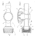
- the numeral 1 indicates generally a fluid flow shut-off and control member, or valve, according to the present invention.
- said valve 1 comprises, as is known, a body 2 wherein is formed the section S for passage of the fluid to be shut off with an appropriate means, controlled by means of a hand lever 3.
- the body 2 extends axially so as to define two opposite ends denoted by reference numerals 2A and 2B, for connection to the pipes.
- the end 2A is of the known type, adapted to achieve, for example, coupling with a safety clamp or similar systems
- the end 2B is shaped so as to allow coupling of said valve 2 with a rotatable ring nut 7, provided with a female screw which will screw onto the corresponding threaded part of a component with a male thread.
- the end 2B of the body 2 bears a flange 4 with two couplings or projections (4A, B) parallel to each other and adapted to engage corresponding teeth 8 disposed in a circle in the inner space 10 of the ring nut 7 ( Figure 4 ).
- the front projection 4A that is the one adjacent to the end of the body 2, chamfered to facilitate entry of the teeth 8 into the flange 4 during assembly of the ring nut 7 with the body 2, is adapted to ensure non return of said ring nut, whereas the rear projection 4B, that is the one situated between the first projection 4A and the hand lever 3, avoids sliding of the ring nut 7 on the body 2, holding the device 1 in place during rotation of the teeth 8 on the flange 4.
- a female thread 10 and a conical gasket 9 the flat seat of which allows the use of pipes of different thicknesses are situated inside the ring nut 7.
- the conical gasket 9 has at least one protruding lip 11 ( Figure 3 ) that engages in the female thread 10 of the ring nut 7 to prevent accidental loss of said gasket, before assembly of the ring nut on the valve body.
- valve 1 with a ring nut 7 on one end but it is obvious that this arrangement does not limit the protection requested since the ring nut can be situated on both of the ends illustrated.
Landscapes
- Engineering & Computer Science (AREA)
- General Engineering & Computer Science (AREA)
- Mechanical Engineering (AREA)
- Preventing Unauthorised Actuation Of Valves (AREA)
- Lift Valve (AREA)
- Centrifugal Separators (AREA)
- Engine Equipment That Uses Special Cycles (AREA)
- Fluid-Pressure Circuits (AREA)
Applications Claiming Priority (1)
| Application Number | Priority Date | Filing Date | Title |
|---|---|---|---|
| IT000012U ITMO20080012U1 (it) | 2008-05-29 | 2008-05-29 | Dispositivo di intercettazione fluidi |
Publications (2)
| Publication Number | Publication Date |
|---|---|
| EP2128508A2 true EP2128508A2 (fr) | 2009-12-02 |
| EP2128508A3 EP2128508A3 (fr) | 2012-06-20 |
Family
ID=40303335
Family Applications (1)
| Application Number | Title | Priority Date | Filing Date |
|---|---|---|---|
| EP20090160446 Withdrawn EP2128508A3 (fr) | 2008-05-29 | 2009-05-15 | Dispositif de coupure de fluides |
Country Status (4)
| Country | Link |
|---|---|
| US (1) | US8074963B2 (fr) |
| EP (1) | EP2128508A3 (fr) |
| AU (1) | AU2009202057A1 (fr) |
| IT (1) | ITMO20080012U1 (fr) |
Cited By (4)
| Publication number | Priority date | Publication date | Assignee | Title |
|---|---|---|---|---|
| CN102913698A (zh) * | 2011-08-05 | 2013-02-06 | 泽特科私人有限公司 | 管道转接接头 |
| JP2015105713A (ja) * | 2013-11-29 | 2015-06-08 | 株式会社Lixil | 管状部材の留め付け構造および小便器 |
| WO2021068984A1 (fr) * | 2019-10-10 | 2021-04-15 | 成都懒到家互联智能科技有限公司 | Ensemble tuyau de raccordement |
| IT202300021486A1 (it) * | 2023-10-16 | 2025-04-16 | Bonomini S R L | Ghiera in plastica per il raccordo di tubi di scarico di lavelli e kit di raccordo comprendente tale ghiera |
Families Citing this family (7)
| Publication number | Priority date | Publication date | Assignee | Title |
|---|---|---|---|---|
| US11628267B2 (en) | 2010-08-04 | 2023-04-18 | Medline Industries, Lp | Universal medical gas delivery system |
| AU2011101764B4 (en) * | 2011-12-15 | 2016-01-28 | Mainrain Pty Ltd | Isolating stop cock valve |
| USD722362S1 (en) * | 2013-12-11 | 2015-02-10 | Reliance Worldwide Corporation | Pressure regulating valve |
| USD722363S1 (en) * | 2013-12-11 | 2015-02-10 | Reliance Worldwide Corporation | Pressure regulating valve |
| AU356871S (en) * | 2014-03-13 | 2014-08-14 | Husqvarna Ab | Connector nut |
| US9781886B1 (en) | 2014-12-19 | 2017-10-10 | Orbit Irrigation Products, Inc. | Hand-securable sprinkler fitting |
| CN106958701A (zh) * | 2017-05-08 | 2017-07-18 | 深圳市聚友缘电子科技有限公司 | 一种接头装置及其操作方法 |
Family Cites Families (17)
| Publication number | Priority date | Publication date | Assignee | Title |
|---|---|---|---|---|
| GB317807A (en) * | 1928-05-17 | 1929-08-19 | Walter Slingsby | Improvements in unions or joint forming connections for metal pipes or tubes |
| GB1172566A (en) * | 1966-03-02 | 1969-12-03 | Ruberoid Co Ltd | Improvements relating to Pipe Unions |
| US4452473A (en) * | 1982-07-26 | 1984-06-05 | Baxter Travenol Laboratories, Inc. | Luer connection system |
| US4582444A (en) * | 1985-01-16 | 1986-04-15 | Miskinis Robert J | Locking and unlocking laboratory joints |
| US5201493A (en) * | 1992-03-12 | 1993-04-13 | Kim Young M | Electrically insulated ball valve device |
| US5360036A (en) * | 1992-08-24 | 1994-11-01 | Nibco, Inc. | Vented ball valve with lock-out ring |
| DE19503722A1 (de) * | 1995-02-04 | 1996-08-08 | Gardena Kress & Kastner Gmbh | Schlauchanschluß, insbesondere zum Anschluß von Schläuchen, wie Gartenschläuchen |
| US5516155A (en) * | 1995-04-26 | 1996-05-14 | Chung Cheng Faucet Co. Ltd. | Water pipe connecting structure |
| US5702374A (en) * | 1995-11-14 | 1997-12-30 | Abbott Laboratories | Male luer connector assembly |
| EP0816741A3 (fr) * | 1996-06-27 | 1999-10-27 | Friatec Aktiengesellschaft | Raccordement par emboítement |
| IT1296847B1 (it) * | 1997-12-05 | 1999-08-02 | Riv Rubinetterie Italiane Valv | Valvola per impianti di conduzione fluidi |
| EP1033516A1 (fr) * | 1999-03-01 | 2000-09-06 | Alessandro Piana | Vanne pour la régulation de fluides |
| US6581593B1 (en) * | 2001-04-03 | 2003-06-24 | Darren A. Rubin | Universal oxygen connector system |
| US6502864B1 (en) * | 2001-08-03 | 2003-01-07 | Donald E. Savard Co. | Universal conduit connector |
| US20050230650A1 (en) * | 2004-04-14 | 2005-10-20 | Rain Bird Corporation | Irrigation valve assembly |
| ITTV20050037A1 (it) * | 2005-03-08 | 2006-09-09 | Fisc Italiana Srl | Struttura di ghiera, particolarmente per il mutuo fissaggio di tubi e/o elementi di raccordo e/o pilette e/o sifoni di lavelli e sanitari. |
| US7810851B2 (en) * | 2008-05-29 | 2010-10-12 | Orbit Irrigation Products, Inc. | Wrenchless manifold |
-
2008
- 2008-05-29 IT IT000012U patent/ITMO20080012U1/it unknown
-
2009
- 2009-05-15 EP EP20090160446 patent/EP2128508A3/fr not_active Withdrawn
- 2009-05-18 US US12/467,623 patent/US8074963B2/en not_active Expired - Fee Related
- 2009-05-25 AU AU2009202057A patent/AU2009202057A1/en not_active Abandoned
Cited By (6)
| Publication number | Priority date | Publication date | Assignee | Title |
|---|---|---|---|---|
| CN102913698A (zh) * | 2011-08-05 | 2013-02-06 | 泽特科私人有限公司 | 管道转接接头 |
| EP2554889A1 (fr) * | 2011-08-05 | 2013-02-06 | Zetco Pty Ltd | Raccord adaptateur de plomberie |
| AU2012208986B2 (en) * | 2011-08-05 | 2016-09-22 | Zetco Valves Pty Ltd | Plumbing Adaptor Fitting |
| JP2015105713A (ja) * | 2013-11-29 | 2015-06-08 | 株式会社Lixil | 管状部材の留め付け構造および小便器 |
| WO2021068984A1 (fr) * | 2019-10-10 | 2021-04-15 | 成都懒到家互联智能科技有限公司 | Ensemble tuyau de raccordement |
| IT202300021486A1 (it) * | 2023-10-16 | 2025-04-16 | Bonomini S R L | Ghiera in plastica per il raccordo di tubi di scarico di lavelli e kit di raccordo comprendente tale ghiera |
Also Published As
| Publication number | Publication date |
|---|---|
| AU2009202057A1 (en) | 2009-12-17 |
| ITMO20080012U1 (it) | 2009-11-29 |
| US8074963B2 (en) | 2011-12-13 |
| US20090293975A1 (en) | 2009-12-03 |
| EP2128508A3 (fr) | 2012-06-20 |
Similar Documents
| Publication | Publication Date | Title |
|---|---|---|
| EP2128508A2 (fr) | Dispositif de coupure de fluides | |
| US10682506B2 (en) | Connecting structure for medical use | |
| JP2011169465A (ja) | パイプ接続アッセンブリー | |
| US6145893A (en) | Connector for pipeline | |
| US20160312906A1 (en) | Diaphragm valve | |
| KR101365228B1 (ko) | 정밀한 압력 및 유량 조절이 가능한 콘 밸브 | |
| RU2011109923A (ru) | Орган управления расходом текучей среды, предназначенный для применения в трубопроводной арматуре | |
| SI23349A (sl) | Krogelna pipa z varovalom spreminjanja nastavitve pretoka tekoäśega medija, mehanizmom stopenjske nastavitve pretoka ter vloĺ˝kom, ki omogoäśa linearen in logaritemski pretok tega medija | |
| WO2009019103A3 (fr) | Ensemble de soupape | |
| US20220396935A1 (en) | Adjustable fluidic coupling | |
| US10088074B2 (en) | Fluid control valve | |
| CN205244708U (zh) | 单闭水流的活接三通 | |
| CN205315910U (zh) | 万向管接头、航空发动机燃滑油系统及航空发动机 | |
| GB2455444A (en) | A plumbing pipe component | |
| JP2019116901A (ja) | 極低温用バルブ | |
| JP5391317B1 (ja) | 精密な圧力及び流量調節が可能なコーン弁 | |
| RU240154U1 (ru) | Кран шаровой | |
| JPS6217478A (ja) | ニ−ドルバルブ | |
| CN223105457U (zh) | 内置减压结构的高密封球阀 | |
| CN205578790U (zh) | 三通阀门 | |
| RU69184U1 (ru) | Шаровой кран | |
| CN217634108U (zh) | 一种可角度调节的放油阀结构 | |
| CN212203162U (zh) | 一种360度可定位旋转龙头 | |
| AU2007100374B4 (en) | Fluid Flow Control Device | |
| US10975972B2 (en) | Control valve connector |
Legal Events
| Date | Code | Title | Description |
|---|---|---|---|
| PUAI | Public reference made under article 153(3) epc to a published international application that has entered the european phase |
Free format text: ORIGINAL CODE: 0009012 |
|
| AK | Designated contracting states |
Kind code of ref document: A2 Designated state(s): AT BE BG CH CY CZ DE DK EE ES FI FR GB GR HR HU IE IS IT LI LT LU LV MC MK MT NL NO PL PT RO SE SI SK TR |
|
| PUAL | Search report despatched |
Free format text: ORIGINAL CODE: 0009013 |
|
| AK | Designated contracting states |
Kind code of ref document: A3 Designated state(s): AT BE BG CH CY CZ DE DK EE ES FI FR GB GR HR HU IE IS IT LI LT LU LV MC MK MT NL NO PL PT RO SE SI SK TR |
|
| AX | Request for extension of the european patent |
Extension state: AL BA RS |
|
| RIC1 | Information provided on ipc code assigned before grant |
Ipc: F16L 19/025 20060101ALI20120511BHEP Ipc: F16L 19/02 20060101AFI20120511BHEP |
|
| STAA | Information on the status of an ep patent application or granted ep patent |
Free format text: STATUS: THE APPLICATION IS DEEMED TO BE WITHDRAWN |
|
| 18D | Application deemed to be withdrawn |
Effective date: 20121201 |