EP2128642A1 - Lichterkennungsmodul für Sternsensor - Google Patents
Lichterkennungsmodul für Sternsensor Download PDFInfo
- Publication number
- EP2128642A1 EP2128642A1 EP08156954A EP08156954A EP2128642A1 EP 2128642 A1 EP2128642 A1 EP 2128642A1 EP 08156954 A EP08156954 A EP 08156954A EP 08156954 A EP08156954 A EP 08156954A EP 2128642 A1 EP2128642 A1 EP 2128642A1
- Authority
- EP
- European Patent Office
- Prior art keywords
- angle
- mainly
- inclination angle
- protection case
- light detector
- Prior art date
- Legal status (The legal status is an assumption and is not a legal conclusion. Google has not performed a legal analysis and makes no representation as to the accuracy of the status listed.)
- Withdrawn
Links
Images

Classifications
-
- G—PHYSICS
- G01—MEASURING; TESTING
- G01S—RADIO DIRECTION-FINDING; RADIO NAVIGATION; DETERMINING DISTANCE OR VELOCITY BY USE OF RADIO WAVES; LOCATING OR PRESENCE-DETECTING BY USE OF THE REFLECTION OR RERADIATION OF RADIO WAVES; ANALOGOUS ARRANGEMENTS USING OTHER WAVES
- G01S3/00—Direction-finders for determining the direction from which infrasonic, sonic, ultrasonic or electromagnetic waves, or particle emission, not having a directional significance, are being received
- G01S3/78—Direction-finders for determining the direction from which infrasonic, sonic, ultrasonic or electromagnetic waves, or particle emission, not having a directional significance, are being received using electromagnetic waves other than radio waves
- G01S3/782—Systems for determining direction or deviation from predetermined direction
- G01S3/785—Systems for determining direction or deviation from predetermined direction using adjustment of orientation of directivity characteristics of a detector or detector system to give a desired condition of signal derived from that detector or detector system
- G01S3/786—Systems for determining direction or deviation from predetermined direction using adjustment of orientation of directivity characteristics of a detector or detector system to give a desired condition of signal derived from that detector or detector system the desired condition being maintained automatically
- G01S3/7867—Star trackers
-
- G—PHYSICS
- G01—MEASURING; TESTING
- G01S—RADIO DIRECTION-FINDING; RADIO NAVIGATION; DETERMINING DISTANCE OR VELOCITY BY USE OF RADIO WAVES; LOCATING OR PRESENCE-DETECTING BY USE OF THE REFLECTION OR RERADIATION OF RADIO WAVES; ANALOGOUS ARRANGEMENTS USING OTHER WAVES
- G01S3/00—Direction-finders for determining the direction from which infrasonic, sonic, ultrasonic or electromagnetic waves, or particle emission, not having a directional significance, are being received
- G01S3/78—Direction-finders for determining the direction from which infrasonic, sonic, ultrasonic or electromagnetic waves, or particle emission, not having a directional significance, are being received using electromagnetic waves other than radio waves
- G01S3/782—Systems for determining direction or deviation from predetermined direction
- G01S3/785—Systems for determining direction or deviation from predetermined direction using adjustment of orientation of directivity characteristics of a detector or detector system to give a desired condition of signal derived from that detector or detector system
- G01S3/786—Systems for determining direction or deviation from predetermined direction using adjustment of orientation of directivity characteristics of a detector or detector system to give a desired condition of signal derived from that detector or detector system the desired condition being maintained automatically
- G01S3/7861—Solar tracking systems
Definitions
- the invention refers to a light detector module for star tracking, i.e. using star light for (artificial) satellite positioning and/or navigation.
- Satellites may orbit the earth with a specific task or purpose. In most cases, the task it has to perform is related to the planet or body it is orbiting, such as measurement of the ozone layer or weather prediction. These satellites are orientated in a specific way with reference to the surface, because it has to perform its task on a specific region.
- the attitude of the satellite has to be determined.
- This attitude is usually determined by the detection of starlight by means of a light detection module in any form.
- the attitude may be calculated using an algorithm which is based on the use of two perpendicular axes. For the calculation of the attitude at least one star has to be detected in each of the two axis. With this knowledge a trajectory or attitude correction may be carried out.
- a light detector module for star tracking comprises at least two detectors, each mounted at the bottom of a protection case, the axes of which protection cases being located within a common plane P1 and extending in a first angle area A1 between a first inclination angle ⁇ to a second inclination angle ⁇ , the end of each protection case being truncated by mainly of at least nearby parallel truncation planes P2, P2' etc. which are mainly perpendicular to said plane P1 and which, moreover, incline, for each protection case, under a third inclination angle ⁇ being within said first angle area A1.
- At least one of the detectors, protected by their protection cases (which preferably have a cylindrical or - more preferably - conical shape) will be not blinded by either directly or indirectly (viz. by reflection via the inner walls of the detector cases) incident light from the sun, due to said mainly of at least nearby parallel truncation planes P2, P2' etc. forming the edge of those (e.g. conical) detection cases.
- the third inclination angle ⁇ may be between a second angle area A2, mainly extending around the value ( ⁇ + ⁇ ) / 2, e.g. extending between the value (( ⁇ + ⁇ ) / 2) - 15°) and (( ⁇ + ⁇ ) / 2) + 15°) or to be mainly equal to ( ⁇ + ⁇ ) / 2, the latter enabling a symmetrical configuration including detector protection cases having identical shapes.
- each protection case may be truncated by mainly parallel truncation planes P2, P2' etc.
- the end of each protection case being truncated by nearby parallel truncation planes P2, P2' etc. having a small positive deviation angle, e.g. being between 0 and 5°.
- such preferred deviation angle of the truncation planes must not pass the value of the opening angle ⁇ of the (e.g. conical) detector case.
- the structure of the protection cases is used to prevent sunlight from reaching (directly or indirectly) all detectors at the same time (i.e. at any altitude of the sun).
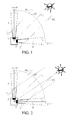
- the exemplary light detector module for star tracking shown in figure 1 comprises two detectors (1,1'), each mounted at the bottom of a protection case (2,2'), the axes (3,3') of which protection cases being located within a common plane P1 equal to the plane of the drawing and extending in a first angle area A1 between a first inclination angle ⁇ to a second inclination angle ⁇ , the end of each protection case being truncated by mainly of at least nearby parallel truncation planes P2, P2' etc. which are mainly perpendicular to said plane P1 and which, moreover, incline, for each protection case, under a third inclination angle ⁇ being within said first angle area A1.
- the third inclination angle ⁇ is between a second angle area A2, mainly extending around the value ( ⁇ + ⁇ ) / 2, e.g. between the value (( ⁇ + ⁇ ) / 2) - 15°) and (( ⁇ + ⁇ ) / 2) + 15°), as indicated in figure 3 .
- the third inclination angle ⁇ is mainly equal to ( ⁇ + ⁇ ) / 2, which is the case in all shown exemplary embodiments except the embodiment shown in figure 3 .
- each protection case is truncated by mainly parallel truncation planes P2, P2', inclined under the same angle ⁇ ( ⁇ ' in figure 3 ).
- both detectors 1, 1' installed in the detection module is to detect star light (e.g. a certain star constellation), as reference for (e.g. satellite) navigation.
- star light e.g. a certain star constellation
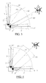
- detector 1 or detector 1' may be blinded by the (abundant) sunlight, so always one detector (viz. the unblended one) will be able to do its job (in figure 2 detector 1' is blinded by the sunlight which is reflected by the inside of the protector case 2', while detector 1 is not blinded).
- figure 1 none of both detectors 1, 1' is blinded, as the sunlight skims over the end edges of both cases 2, 2'.
- each protection case truncated by truncation planes P2, P2' having a small positive (i.e. diverging towards the sun) deviation angle ⁇ , resulting in "security areas", indicated in figure 4 by circles at the lower sides of the protection cylinders 2, 2'.
- the deviation angle ⁇ may lie between 0 and 5°.
- figure 5 shows an embodiment having detector protection cases with minimal length, showing that the length of the case is not important as such for a proper operation of the configuration.
- Figure 6 shows outlines an alternative housing for the detectors and the cases, in which the cases are more inside the housing and are an integrated part of it, which may have advantages in view of the manufacture of the complete module.
- Figure 7 shows an embodiment in which the angle area A1 (i.e. the difference between the inclination angles ⁇ and ⁇ of the central axes of the detector cases) is smaller than in the previous embodiments (i.e. smaller than 90°) and showing that the configuration will operate proper as well.
- the angle area A1 i.e. the difference between the inclination angles ⁇ and ⁇ of the central axes of the detector cases
Landscapes
- Physics & Mathematics (AREA)
- Engineering & Computer Science (AREA)
- Radar, Positioning & Navigation (AREA)
- Remote Sensing (AREA)
- Electromagnetism (AREA)
- General Physics & Mathematics (AREA)
- Life Sciences & Earth Sciences (AREA)
- Sustainable Development (AREA)
- Navigation (AREA)
Priority Applications (2)
| Application Number | Priority Date | Filing Date | Title |
|---|---|---|---|
| EP08156954A EP2128642A1 (de) | 2008-05-27 | 2008-05-27 | Lichterkennungsmodul für Sternsensor |
| PCT/NL2009/050294 WO2009145628A1 (en) | 2008-05-27 | 2009-05-27 | Light detection module for star tracking |
Applications Claiming Priority (1)
| Application Number | Priority Date | Filing Date | Title |
|---|---|---|---|
| EP08156954A EP2128642A1 (de) | 2008-05-27 | 2008-05-27 | Lichterkennungsmodul für Sternsensor |
Publications (1)
| Publication Number | Publication Date |
|---|---|
| EP2128642A1 true EP2128642A1 (de) | 2009-12-02 |
Family
ID=39831792
Family Applications (1)
| Application Number | Title | Priority Date | Filing Date |
|---|---|---|---|
| EP08156954A Withdrawn EP2128642A1 (de) | 2008-05-27 | 2008-05-27 | Lichterkennungsmodul für Sternsensor |
Country Status (2)
| Country | Link |
|---|---|
| EP (1) | EP2128642A1 (de) |
| WO (1) | WO2009145628A1 (de) |
Citations (8)
| Publication number | Priority date | Publication date | Assignee | Title |
|---|---|---|---|---|
| GB2185335A (en) * | 1986-01-11 | 1987-07-15 | Messerschmitt Boelkow Blohm | Space telescope optically connected to a star tracker |
| EP0338687A2 (de) * | 1988-04-20 | 1989-10-25 | British Aerospace Public Limited Company | Verfahren und Vorrichtung, um einen die Erde umkreisenden Raumflugkörper nach einer Lagerverschiebung zu einer zur Erde weisenden Lage zurückzuführen |
| JPH02147813A (ja) * | 1988-11-29 | 1990-06-06 | Toshiba Corp | 2軸スターセンサ |
| US5745869A (en) * | 1995-09-28 | 1998-04-28 | Lockheed Missiles & Space Company, Inc. | Techniques for optimizing an autonomous star tracker |
| EP1111402A1 (de) * | 1999-12-20 | 2001-06-27 | TRW Inc. | Sternenabtaster mit CCDs für Umgebung mit starker Strahlung |
| JP2002131078A (ja) * | 2000-10-26 | 2002-05-09 | Mitsubishi Electric Corp | スターセンサシステム |
| WO2008044931A1 (en) * | 2006-10-12 | 2008-04-17 | Nederlandse Organisatie Voor Toegepast-Natuurwetenschappelijk Onderzoek Tno | Star tracker with baffle |
| WO2008048478A2 (en) * | 2006-10-13 | 2008-04-24 | Soliant Energy, Inc. | Sun sensor assembly and related method of using |
-
2008
- 2008-05-27 EP EP08156954A patent/EP2128642A1/de not_active Withdrawn
-
2009
- 2009-05-27 WO PCT/NL2009/050294 patent/WO2009145628A1/en not_active Ceased
Patent Citations (8)
| Publication number | Priority date | Publication date | Assignee | Title |
|---|---|---|---|---|
| GB2185335A (en) * | 1986-01-11 | 1987-07-15 | Messerschmitt Boelkow Blohm | Space telescope optically connected to a star tracker |
| EP0338687A2 (de) * | 1988-04-20 | 1989-10-25 | British Aerospace Public Limited Company | Verfahren und Vorrichtung, um einen die Erde umkreisenden Raumflugkörper nach einer Lagerverschiebung zu einer zur Erde weisenden Lage zurückzuführen |
| JPH02147813A (ja) * | 1988-11-29 | 1990-06-06 | Toshiba Corp | 2軸スターセンサ |
| US5745869A (en) * | 1995-09-28 | 1998-04-28 | Lockheed Missiles & Space Company, Inc. | Techniques for optimizing an autonomous star tracker |
| EP1111402A1 (de) * | 1999-12-20 | 2001-06-27 | TRW Inc. | Sternenabtaster mit CCDs für Umgebung mit starker Strahlung |
| JP2002131078A (ja) * | 2000-10-26 | 2002-05-09 | Mitsubishi Electric Corp | スターセンサシステム |
| WO2008044931A1 (en) * | 2006-10-12 | 2008-04-17 | Nederlandse Organisatie Voor Toegepast-Natuurwetenschappelijk Onderzoek Tno | Star tracker with baffle |
| WO2008048478A2 (en) * | 2006-10-13 | 2008-04-24 | Soliant Energy, Inc. | Sun sensor assembly and related method of using |
Also Published As
| Publication number | Publication date |
|---|---|
| WO2009145628A1 (en) | 2009-12-03 |
Similar Documents
| Publication | Publication Date | Title |
|---|---|---|
| US10717549B2 (en) | Spacecraft for space debris removal | |
| US9531081B2 (en) | Reflector antenna for a synthetic aperture radar | |
| JP7270831B2 (ja) | 衛星コンステレーション、地上設備および飛翔体追跡システム | |
| CN104296751B (zh) | 一种多星敏感器构型布局设计方法 | |
| CN106595673B (zh) | 面对地球静止轨道目标操作的空间多机器人自主导航方法 | |
| US7924415B2 (en) | Apparatus and method for a light direction sensor | |
| US20180017394A1 (en) | Planetary Surveillance System | |
| ES3036409T3 (en) | Method and device for determining a pointing law for a satellite by determining a space-time distribution | |
| US20030029970A1 (en) | Spacecraft methods and structures for acquiring and determining power-safe attitudes | |
| US5618012A (en) | Satellite stabilization system | |
| EP2128642A1 (de) | Lichterkennungsmodul für Sternsensor | |
| Bally et al. | Deep imaging surveys of star-forming clouds. IV. The meek and the mighty: outflows from young stars in Chamaeleon I | |
| CN103983231B (zh) | 一种底座及使用该底座的红外地平仪 | |
| US20090153938A1 (en) | Method for enhanced detection of faint targets in systems employing an external occulter | |
| Shugarov et al. | System of Observation of Day-time Asteroids (SODA) | |
| Kucharski et al. | Optical response of nanosatellite BLITS measured by the Graz 2 kHz SLR system | |
| CN113553695A (zh) | 一种兼顾来自太阳方向小行星预警与小行星编目的方法 | |
| Bayer et al. | The trigger logic of EUSO-SPB and its performance | |
| RU2621816C1 (ru) | Способ определения выходной мощности солнечной батареи космического аппарата | |
| CN106444002B (zh) | 光学望远镜 | |
| Korotkov et al. | A pinhole sun sensor for balloon-borne experiment attitude determination | |
| CN107796405B (zh) | 面向深空探测巡航段的恒星测速导航仪在轨跟踪方法 | |
| Krymsky et al. | Observation of a beam of ultrarelativistic particles and the Cherenkov resonance | |
| Kun-peng et al. | Research on the Optical Observation Method for LEO Objects with Small Inclination | |
| Majumder et al. | Physical Modelling of Sensor FOV Blockages and Hybrid Mode Sensing Based Sun Acquisition |
Legal Events
| Date | Code | Title | Description |
|---|---|---|---|
| PUAI | Public reference made under article 153(3) epc to a published international application that has entered the european phase |
Free format text: ORIGINAL CODE: 0009012 |
|
| AK | Designated contracting states |
Kind code of ref document: A1 Designated state(s): AT BE BG CH CY CZ DE DK EE ES FI FR GB GR HR HU IE IS IT LI LT LU LV MC MT NL NO PL PT RO SE SI SK TR |
|
| AX | Request for extension of the european patent |
Extension state: AL BA MK RS |
|
| AKY | No designation fees paid | ||
| REG | Reference to a national code |
Ref country code: DE Ref legal event code: 8566 |
|
| STAA | Information on the status of an ep patent application or granted ep patent |
Free format text: STATUS: THE APPLICATION IS DEEMED TO BE WITHDRAWN |
|
| 18D | Application deemed to be withdrawn |
Effective date: 20100603 |