EP2128766A2 - Système d'appareil électronique ayant plusieurs appareils assemblés sur une étagère, et procédé d'identification d'appareil électronique dans un système d'appareil électronique - Google Patents
Système d'appareil électronique ayant plusieurs appareils assemblés sur une étagère, et procédé d'identification d'appareil électronique dans un système d'appareil électronique Download PDFInfo
- Publication number
- EP2128766A2 EP2128766A2 EP09153457A EP09153457A EP2128766A2 EP 2128766 A2 EP2128766 A2 EP 2128766A2 EP 09153457 A EP09153457 A EP 09153457A EP 09153457 A EP09153457 A EP 09153457A EP 2128766 A2 EP2128766 A2 EP 2128766A2
- Authority
- EP
- European Patent Office
- Prior art keywords
- electronic apparatus
- light emitting
- electronic
- emitting devices
- control
- Prior art date
- Legal status (The legal status is an assumption and is not a legal conclusion. Google has not performed a legal analysis and makes no representation as to the accuracy of the status listed.)
- Granted
Links
Images


Classifications
-
- G—PHYSICS
- G06—COMPUTING OR CALCULATING; COUNTING
- G06F—ELECTRIC DIGITAL DATA PROCESSING
- G06F11/00—Error detection; Error correction; Monitoring
- G06F11/30—Monitoring
- G06F11/32—Monitoring with visual or acoustical indication of the functioning of the machine
- G06F11/324—Display of status information
- G06F11/325—Display of status information by lamps or LED's
- G06F11/326—Display of status information by lamps or LED's for error or online/offline status
Definitions
- the present invention relates to an electronic apparatus system and a method for performing identification processing of an electronic apparatus, for identifying an installation location of a faulty electronic apparatus in an electronic apparatus system having a multiplicity of electronic apparatuses on a rack, and more particularly an electronic apparatus system and a method for performing identification processing of an electronic apparatus, for identifying the installation location of a faulty electronic apparatus using status display lamps of other electronic apparatuses.
- a parallel computer system is configured of server units on the order of a thousand sets connected in parallel.
- the system is configured of several hundreds of magnetic disk units (hard disk units). The tendency is also the same in communication apparatus.
- FIG. 15 is an explanation diagram of the conventional method for identifying the physical location of the rack-mounted electronic apparatus.
- a server unit As an electronic apparatus, the description of a server unit is given as an example.
- a multiplicity of server units 90 are mounted on a multiplicity of racks 1-n.
- six (6) sets of the server units 90 are mounted on a single rack, and there are arranged such racks in the number of n (100, for example).
- Each server unit 90 is connected to a control server unit 92 to control the entire server units 90, through a control LAN (Local Area Network) 94.
- the control server unit 92 includes a server location information table 96 which stores an IP (Internet Protocol) address, a host name, a rack number, and a shelf-level number of the rack for each server unit.
- the table 96 is generated in advance by the input from a system administrator.
- control server unit 90 When the control server unit 90 is notified of an abnormality notification from the server unit 90 through the control LAN 94, the control server unit 90 displays the rack number of the server unit 90 and the shelf-level number of the rack by referring to the table 96 according to the notified IP address. As such, the physical location of the server unit 90 having sent the abnormality notification has conventionally been identified.
- Embodiments of the present invention may provide an electronic apparatus system, and a method for performing identification processing of the physical location of an electronic apparatus, for identifying the physical location of the electronic apparatus having sent an abnormality notification among the electronic apparatuses mounted on the multiplicity of racks, using status display devices of the electronic apparatuses.
- Embodiments may also provide an electronic apparatus system, and a method for performing identification processing of the physical location of an electronic apparatus, for identifying the physical location of the electronic apparatus having sent an abnormality notification, using status display devices of the electronic apparatuses, even when a display status by the status display device of the electronic apparatus cannot be changed.
- Embodiments may further provide an electronic apparatus system, and a method for performing identification processing of the physical location of an electronic apparatus, for identifying the physical location of the electronic apparatus having sent an abnormality notification, without need of adding special hardware, and/or without need of inputting physical location information of a server unit group in advance.
- an electronic apparatus system including: a plurality of racks mounting a plurality of electronic apparatuses; a light emitting device provided on each the electronic apparatus; a network connecting each the electronic apparatus; and a control electronic apparatus receiving an abnormality notification of the electronic apparatus through the network, controlling the light emitting devices of the electronic apparatuses on the rack mounting the electronic apparatus having sent the abnormality notification to be in an identical display mode, and thereafter controlling one display mode of the light emitting device of the electronic apparatus having sent the abnormality notification to be different from other display modes of the light emitting devices of the other electronic apparatuses.
- a processing method for identifying a physical location of an electronic apparatus includes the steps of: receiving an abnormality notification of the electronic apparatus through a network connecting a plurality of electronic apparatuses mounted on a plurality of racks; controlling light emitting devices of the entire electronic apparatuses on the rack mounting the electronic apparatus having sent the abnormality notification to be in an identical display mode; and controlling one display mode of the light emitting device of the electronic apparatus having sent the abnormality notification to be different from other display modes of light emitting devices of the other electronic apparatuses.
- control electronic apparatus controls to turn on the light emitting devices of the other electronic apparatuses according to the light emitting device of the electronic apparatus having sent the abnormality notification being faulty.
- control electronic apparatus communicates with each the electronic apparatus through the network to confirm normality or abnormality, and the other electronic apparatus performs display control of the light emitting devices of the electronic apparatuses in behalf of the control electronic apparatus when the control electronic apparatus is abnormal.
- control electronic apparatus controls the light emitting devices of the electronic apparatuses on the rack mounting the electronic apparatus having sent the abnormality notification to be in an identical display mode by issuing a broadcast command using an IP address including the rack number.
- an electronic apparatus system wherein the light emitting devices are disposed on a front face and a back face of the electronic apparatus.
- an electronic apparatus system according to the present invention, wherein the identical display mode of the light emitting devices of the electronic apparatuses on the rack mounting the electronic apparatus having sent the abnormality notification is blinks of the light emitting devices.
- an electronic apparatus system according to the present invention, wherein, the electronic apparatus changes rhythm of the blinks of the light emitting devices according to an operation condition of the electronic apparatus.
- the light emitting devices of the entire electronic apparatuses on a rack are displayed, and the rack location is identified from among a plurality of racks. Then, because the light emitting device of the electronic apparatus having sent an abnormality notification are changed from the light emitting device display mode of another electronic apparatus, it is easy to identify the physical location of the electronic apparatus having sent the abnormality notification.
- Preferred embodiments of the present invention will be described hereinafter in the order of an electronic apparatus system, LED display processing, processing for identifying a physical location of an abnormal electronic apparatus, substitutive processing for the physical location identification processing, and other embodiments.
- FIG. 1 is a configuration diagram of the electronic apparatus system according to one embodiment of the present invention
- FIG. 2 is a front view of a server unit shown in FIG. 1
- FIG. 3 is a rear view of the server unit shown in FIG. 1
- FIG. 4 is a configuration diagram of the server unit according to FIG. 1
- FIG. 5 is a configuration diagram of a system control section shown in FIG. 4 .
- the server unit is indicated as an example of the electronic apparatus.
- a plurality of server units 1 are mounted on a plurality of racks 1 - (n+3).
- six (6) server units 1 are mounted on single rack, and such racks are arranged in a plurality of rows by the number of n+3 (150 as an example).
- a connection between each server unit 1 and a control server unit 1-1 for controlling the entire server units 1 is made by use of a control LAN (Local Area Network) 9.
- LAN Local Area Network
- each server unit 1 two light emitting devices (LEDs) 2, namely one LED in front and the other LED in back, are mounted to display abnormality of the unit.
- LEDs light emitting devices
- FIG. 2 on the front face of the server unit 2, a status check lamp 2-1 is provided in addition to a ready lamp RED, and a link lamp LINK.
- a status check lamp 2-2 is provided in addition to a ready lamp RED, and a link lamp LINK.
- Mounting check lamps 2-1, 2-2 respectively in front and in back of the server unit 1 is effective that changed displays of check lamps 2-1, 2-2 can be seen from both the front face side and the back face side of the server unit 1.
- the control server unit 1-1 has functions of blinking and turning on and off the check lamps 2 (2-1, 2-2) on each server unit 1, via the LAN.
- each server unit 1, 1-1 includes four (4) CPU blocks 10-13, a system control section 14 for performing system control of the CPU blocks 10-13, and a unit block 16 having an operator panel (OPNL) including the aforementioned check lamps 2, a fan (FAN) and a power supply (PSU).
- OPNL operator panel
- FAN fan
- PSU power supply
- the system control block 14 is connected to the control server 1-1 via the control LAN 9, and communicates with each CPU block 10-13 (CPU 100) via a system management circuit 122.
- Each CPU block 10-13 includes a CPU (Central Processing Unit) 100, a magnetic disk unit 114, an interference circuit 112 interfacing with both the magnetic disk unit 114 and the LAN to interconnect the servers, and a first bridge circuit 116 for connecting between the interference circuit 112 and the CPU 100. Further, a second bridge circuit 120 is provided for using two neighboring interference circuits 112 between the neighboring CPUs 100.
- CPU Central Processing Unit
- the system control section 14 includes a transceiver/receiver 141 for the connection of the control LAN 9; an LED controller 142 for control to turn on and blink of the aforementioned check lamp 2-2 provided on the back face of the unit; an MPU (Microprocessor Unit) 143; a memory 144; a monitor/power supply control circuit 145 for performing the status monitoring and the status control of power supplies, fans and the CPU blocks 10-13; LED (check lamp) 2-1 disposed on the unit surface; and an LED control circuit (not shown) for controlling the LED.
- MPU Microprocessor Unit
- the memory 144 stores a unit configuration table 144-1, which will be described in FIG. 10 , and a flag indicating "master" or "local".
- the MPU 143 performs turn-on control (LED display processing) of the check lamps 2-1, 2-2 initiated by commands being input through control LAN 9, also substitutes the role of the control server unit according to a Master command.
- the control server unit 1-1 also has the configuration shown in FIGS. 4 and 5 .
- FIG. 6 is an explanation diagram of LED processing modes in the system control section 14.
- FIG. 7 is a processing flowchart of the self-diagnosis mode shown in FIG. 6 .
- FIG. 8 is a processing flowchart of the standby mode.
- the MPU 143 in the system control section 14 transfers a LED display processing status from among a self-diagnosis in-progress mode A at the time of performing self-diagnosis ( FIG. 7 ), a standby mode B at the time of the server unit 1 being in operation ( FIG. 8 ), and a physical location identification mode ( FIG. 9 and thereafter) to identify an abnormal server unit.
- the MPU 143 receives a self-diagnosis result from the CPU block 10-13 and, if the result represents an abnormality of the diagnosis, the MPU 143 turns on the check lamps (LEDs) 2-1, 2-2.
- the check lamps 2-1, 2-2 display the self-diagnosis status and the self-diagnosis result of the server unit 1.
- the MPU 143 judges whether a physical location identification command has been received from the control LAN 9. On receipt of the physical location identification command from the control LAN 9, the MPU 143 transfers the status from the standby mode to the physical location identification mode ( FIG. 9 ), and obeys commands from the control server unit. Additionally, on receipt of a release command from the LAN 9, the MPU 143 transfers the status from the physical location identification mode to the standby mode.
- the MPU 143 Under the standby mode, the MPU 143 receives a status notification of either one of job-in-operation and in-wait from the software of the CPU block 10-13, and judges whether presently the job is in operation.
- the MPU 143 turns the check lamps (LEDs) 2-1, 2-2 on and off at a slow rate (i.e. in a long period), and returns to step S22.
- the MPU 143 judges whether or not the CPU blocks 10-13 has sent a fault notification. If the notification has not been sent, the MPU 143 turns off the check lamps (LEDs) 2-1, 2-2, and returns to step S22.
- the check lamps (LEDs) 2-1, 2-2 display the job execution status of the server unit 1, as well as whether or not the server unit 1 is faulty.
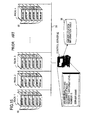
- FIG. 9 is a flowchart of physical location identification processing according to one embodiment of the present invention.
- FIG. 10 is an explanation diagram of a processing sequence.
- FIG. 11 is an explanation diagram of a configuration definition table in the system control section described in FIG. 5 .
- FIG. 12 is an explanation diagram of a broadcast command to identify the physical location.
- IP address of the server unit on the control LAN 9 will be described.
- a subnet address is assigned on the rack-by-rack basis to the IP (Internet Protocol) address of the server unit 1 mounted on each rack.
- IP Internet Protocol
- the description will be given to an exemplary case of 128 server units 1 being mounted on 16 racks, each having 8 shelf levels.
- the level number is set in the lowest digit of the IP address, and the rack number is set in the second and the third digits from the lowest.
- the IP address is set to "192.168.11.1".
- the lowest digit "1" indicates the shelf-level number
- the second and the third digits from the lowest digit, namely "11” indicate the rack number.
- the server unit 1 having the unit number 8 is mounted on the eighth level of the rack number 1, the IP address is set to "192.168.11.8".
- a broadcast command as a location identification command.
- the IP address to be added to a command here, "setlocator blink” command to blink LEDs
- a command to blink the LEDs of the entire 8 units mounted on the rack having the rack number 1 is signified.
- the control server 1-1 has a function of shifting the LED display mode of the entire server units 1 on a rack, from the IP address of server unit 1 having output a fault notification.
- FIG. 9 is the physical location identification processing in the server unit 1, when a fault is detected through self-diagnosis processing after switching on the unit power shown in FIG. 7 .
- FIG. 10 the processing indicated in FIG. 9 will be explained.
- the server unit 1 judges whether or not the command from the control server 1-1 is an LED release command. When the server unit 1 judges that the command is the LED release command, the server unit 1 shifts to the standby mode, as described earlier in FIG. 6 .
- the control server 1-1 instructs to turn off LEDs 2-1, 2-2 on the entire server units 1 of the rack.
- LEDs (check lamps) 2-1, 2-2 disposed in front and in back of the entire server units 1 on the rack of interest (for example, the rack having the rack number 1) are turned off.
- the control server 1-1 instructs to blink LEDs 2-1, 2-2 of the faulty server unit 1 only.
- the LEDs (check lamps) 2-1, 2-2 of the faulty server unit 1 come to blink, so long as a fault does not exist.
- the LEDs of interest come to blink. Therefore, in case that the faulty server unit 1 can accept the command, and that both the LED 2-1, 2-2 nor the control circuit is not faulty, it is possible to identify the physical location of the faulty server unit 1 on the rack of interest.
- the faulty server unit 1 performs self-diagnosis of the LEDs 2-1, 2-2 (including the control circuit thereof). Then, the faulty server unit 1 notifies the control server 1-1 of the self-diagnosis result. When the control server 1-1 decides that the self-diagnosis result is normal, the server unit 1 returns to step S30, because the physical location of the faulty server unit 1 could be identified.
- step S40 On the other hand, when the self-diagnosis result of the server unit 1 is abnormal, there is a fault in the LED 2-1, 2-2, and as a result, the LED 2-1, 2-2 concerned does not blink in step S36. Therefore, it is not possible to identify the physical location of the faulty server unit 1 in step S36. Accordingly, the control server 1-1 instructs to turn off the LEDs 2-1, 2-2 of the entire server units 1 on the rack of interest by using abovementioned broadcast command. With this, the LEDs (check lamps) 2-1, 2-2 disposed in front and in back of the entire server units 1 of the rack of interest (for example, the rack having the rack number 1) are turned off.
- the control server 1-1 instructs to blink the LEDs 2-1, 2-2 of the server units 1 other than the faulty server unit 1.
- the LEDs (check lamps) 2-1, 2-2 of the server units 1 other than the faulty server unit 1 come to blink.
- the LEDs 2-1, 2-2 of the faulty server unit 1 are kept in the light-off state. Then, a 30-second wait is made. Namely, blinks are repeated for 30 seconds. With this, among a plurality of racks, it is possible to physically recognize the rack on which the faulty server unit is mounted. Then the process returns to step S30.
- the LEDs of the entire server units of the rack on which the faulty server unit is mounted are blinked, so that the rack location is identified. Then, the LEDs of the faulty server unit are blinked, and thus, the physical location of the faulty server unit at the rack location is identified. As a result, it is easily possible to identify the physical location of the faulty server unit, even when a plurality of racks are installed.
- the LEDs of the faulty server unit do not work, the LEDs of the entire server units on which the faulty server unit is mounted are turned off. Next, the LEDs of the server units other than the faulty server unit are blinked. Thus, the physical location of the faulty server unit at the rack location is identified.
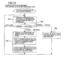
- FIG. 13 is a flowchart of the substitutive processing to identify the physical location of the server unit according to one embodiment of the present invention.
- FIG. 14 is an explanation diagram of a processing sequence indicated in FIG. 13 .
- control server 1-1 and each server unit 1 periodically confirm PING response to confirm each being active or disabled, and detects whether normality or abnormality of the control server 1-1 and server unit 1.
- step S52 By confirming a PING response, the server unit 1 decides whether or not the status changes from being normal to abnormal, or from being abnormal to normal. On deciding the status has not changed, the server unit 1 returns to step S50.
- the server 1 On deciding that the status of the control server 1-1 has changed from being normal to abnormal, the server 1 shifts the mode from a remote mode (remote operation mode from the control server 1-1) to a local mode. Then, the server unit 1,which is in a normal state within the rack among the plurality of server units 1 and has the smallest IP address value, changes a mode to a master state. Further, server unit 1 in the master state instructs other server units 1 on the rack concerned to shift to the local mode.
- a remote mode remote operation mode from the control server 1-1
- the server unit 1 which is in a normal state within the rack among the plurality of server units 1 and has the smallest IP address value, changes a mode to a master state. Further, server unit 1 in the master state instructs other server units 1 on the rack concerned to shift to the local mode.
- the master server unit executes the physical location identification processing S30-S42 shown in FIG. 9 , which has been executed by the control server 1-1.
- any other server unit 1 can perform physical location identification processing in a substitutive manner.
- the present invention is also applicable to a storage unit such as a magnetic disk unit and a communication unit.
- the blink display in the physical location identification processing may be modified to light-on display.
Landscapes
- Engineering & Computer Science (AREA)
- Theoretical Computer Science (AREA)
- Quality & Reliability (AREA)
- Physics & Mathematics (AREA)
- General Engineering & Computer Science (AREA)
- General Physics & Mathematics (AREA)
- Debugging And Monitoring (AREA)
Applications Claiming Priority (1)
| Application Number | Priority Date | Filing Date | Title |
|---|---|---|---|
| JP2008085365A JP5115272B2 (ja) | 2008-03-28 | 2008-03-28 | 多数の電子機器をラック搭載した電子機器システム及び電子機器システムの電子機器の特定処理方法。 |
Publications (3)
| Publication Number | Publication Date |
|---|---|
| EP2128766A2 true EP2128766A2 (fr) | 2009-12-02 |
| EP2128766A3 EP2128766A3 (fr) | 2010-10-13 |
| EP2128766B1 EP2128766B1 (fr) | 2012-06-06 |
Family
ID=41116268
Family Applications (1)
| Application Number | Title | Priority Date | Filing Date |
|---|---|---|---|
| EP09153457A Ceased EP2128766B1 (fr) | 2008-03-28 | 2009-02-23 | Système d'appareil électronique ayant plusieurs appareils assemblés sur une étagère, et procédé d'identification d'appareil électronique dans un système d'appareil électronique |
Country Status (3)
| Country | Link |
|---|---|
| US (1) | US8223015B2 (fr) |
| EP (1) | EP2128766B1 (fr) |
| JP (1) | JP5115272B2 (fr) |
Cited By (2)
| Publication number | Priority date | Publication date | Assignee | Title |
|---|---|---|---|---|
| US8914495B2 (en) | 2011-06-07 | 2014-12-16 | International Business Machines Corporation | Automatically detecting and locating equipment within an equipment rack |
| EP2702489B1 (fr) * | 2011-04-26 | 2020-03-18 | Bull SAS | Dispositif de reperage pour reperer une armoire informatique parmi une pluralite d'armoires informatiques |
Families Citing this family (48)
| Publication number | Priority date | Publication date | Assignee | Title |
|---|---|---|---|---|
| US9648907B2 (en) * | 2005-05-31 | 2017-05-16 | Philip Morris Usa Inc. | Virtual reality smoking system |
| US20090023431A1 (en) * | 2007-07-19 | 2009-01-22 | Hewlett-Packard Development Company, L.P. | Systems and Methods for Communicating with a Network Switch |
| JP5115272B2 (ja) * | 2008-03-28 | 2013-01-09 | 富士通株式会社 | 多数の電子機器をラック搭載した電子機器システム及び電子機器システムの電子機器の特定処理方法。 |
| US8484162B2 (en) | 2008-06-24 | 2013-07-09 | Commvault Systems, Inc. | De-duplication systems and methods for application-specific data |
| US8930306B1 (en) | 2009-07-08 | 2015-01-06 | Commvault Systems, Inc. | Synchronized data deduplication |
| US20110047188A1 (en) * | 2009-08-24 | 2011-02-24 | Carios Martins | Method and System for Automatic Tracking of Information Technology Components and Corresponding Power Outlets in a Data Center |
| US9298581B2 (en) * | 2010-03-26 | 2016-03-29 | Microsoft Technology Licensing, Llc | Dynamically controlled server rack illumination system |
| US11449394B2 (en) | 2010-06-04 | 2022-09-20 | Commvault Systems, Inc. | Failover systems and methods for performing backup operations, including heterogeneous indexing and load balancing of backup and indexing resources |
| US8427301B2 (en) * | 2010-06-24 | 2013-04-23 | Avocent Corporation | System and method for identifying electrical equipment using wireless receivers |
| US9020900B2 (en) | 2010-12-14 | 2015-04-28 | Commvault Systems, Inc. | Distributed deduplicated storage system |
| US20120150818A1 (en) | 2010-12-14 | 2012-06-14 | Commvault Systems, Inc. | Client-side repository in a networked deduplicated storage system |
| US9547575B2 (en) * | 2011-08-30 | 2017-01-17 | Amazon Technologies, Inc. | Managing host computing devices |
| US20130204984A1 (en) * | 2012-02-08 | 2013-08-08 | Oracle International Corporation | Management Record Specification for Management of Field Replaceable Units Installed Within Computing Cabinets |
| JP5914385B2 (ja) * | 2012-05-09 | 2016-05-11 | 太平洋工業株式会社 | サーバ監視装置及びサーバ監視システム |
| US9218376B2 (en) | 2012-06-13 | 2015-12-22 | Commvault Systems, Inc. | Intelligent data sourcing in a networked storage system |
| US9633033B2 (en) | 2013-01-11 | 2017-04-25 | Commvault Systems, Inc. | High availability distributed deduplicated storage system |
| US9335786B2 (en) | 2013-02-28 | 2016-05-10 | Oracle International Corporation | Adapter facilitating blind-mate electrical connection of field replaceable units with virtual backplane of computing rack |
| US10338653B2 (en) | 2013-02-28 | 2019-07-02 | Oracle International Corporation | Power delivery to rack-mounted field replaceable units using AC and/or DC input power sources |
| US9936603B2 (en) | 2013-02-28 | 2018-04-03 | Oracle International Corporation | Backplane nodes for blind mate adapting field replaceable units to bays in storage rack |
| US9116619B2 (en) * | 2013-05-10 | 2015-08-25 | Seagate Technology Llc | Displaying storage device status conditions using multi-color light emitting diode |
| TWI501079B (zh) * | 2013-12-19 | 2015-09-21 | Inventec Corp | 伺服器機櫃系統、電路板組合系統及其電路板 |
| US9251496B2 (en) | 2014-02-25 | 2016-02-02 | International Business Machines Corporation | Light pulse object identification |
| US10380072B2 (en) | 2014-03-17 | 2019-08-13 | Commvault Systems, Inc. | Managing deletions from a deduplication database |
| US9563518B2 (en) | 2014-04-02 | 2017-02-07 | Commvault Systems, Inc. | Information management by a media agent in the absence of communications with a storage manager |
| US9330543B2 (en) * | 2014-06-23 | 2016-05-03 | International Business Machines Corporation | Managing serviceability modes |
| US9575673B2 (en) | 2014-10-29 | 2017-02-21 | Commvault Systems, Inc. | Accessing a file system using tiered deduplication |
| US10339106B2 (en) | 2015-04-09 | 2019-07-02 | Commvault Systems, Inc. | Highly reusable deduplication database after disaster recovery |
| US20160350391A1 (en) | 2015-05-26 | 2016-12-01 | Commvault Systems, Inc. | Replication using deduplicated secondary copy data |
| US10592357B2 (en) | 2015-12-30 | 2020-03-17 | Commvault Systems, Inc. | Distributed file system in a distributed deduplication data storage system |
| CN107870846B (zh) * | 2016-09-23 | 2021-04-02 | 伊姆西Ip控股有限责任公司 | 故障元件指示方法、设备和系统 |
| US10474548B2 (en) | 2016-09-30 | 2019-11-12 | Commvault Systems, Inc. | Heartbeat monitoring of virtual machines for initiating failover operations in a data storage management system, using ping monitoring of target virtual machines |
| EP3664635B1 (fr) * | 2017-08-09 | 2025-05-21 | Philip Morris Products S.A. | Dispositif générateur d'aérosol doté d'un dispositif de chauffage par induction avec une bobine d'induction conique |
| US11284646B2 (en) | 2018-03-22 | 2022-03-29 | Altria Client Services Llc | Augmented reality and/or virtual reality based e-vaping device vapor simulation systems and methods |
| US11016696B2 (en) | 2018-09-14 | 2021-05-25 | Commvault Systems, Inc. | Redundant distributed data storage system |
| US10962389B2 (en) | 2018-10-03 | 2021-03-30 | International Business Machines Corporation | Machine status detection |
| US11010258B2 (en) | 2018-11-27 | 2021-05-18 | Commvault Systems, Inc. | Generating backup copies through interoperability between components of a data storage management system and appliances for data storage and deduplication |
| US11200124B2 (en) | 2018-12-06 | 2021-12-14 | Commvault Systems, Inc. | Assigning backup resources based on failover of partnered data storage servers in a data storage management system |
| US11698727B2 (en) | 2018-12-14 | 2023-07-11 | Commvault Systems, Inc. | Performing secondary copy operations based on deduplication performance |
| US20200327017A1 (en) | 2019-04-10 | 2020-10-15 | Commvault Systems, Inc. | Restore using deduplicated secondary copy data |
| US11463264B2 (en) | 2019-05-08 | 2022-10-04 | Commvault Systems, Inc. | Use of data block signatures for monitoring in an information management system |
| US20210173811A1 (en) | 2019-12-04 | 2021-06-10 | Commvault Systems, Inc. | Optimizing the restoration of deduplicated data stored in multi-node replicated file systems |
| US11099956B1 (en) | 2020-03-26 | 2021-08-24 | Commvault Systems, Inc. | Snapshot-based disaster recovery orchestration of virtual machine failover and failback operations |
| US11687424B2 (en) | 2020-05-28 | 2023-06-27 | Commvault Systems, Inc. | Automated media agent state management |
| US11682592B2 (en) * | 2020-10-09 | 2023-06-20 | Dell Products L.P. | Method and system for automated checking and validation of light emitting diodes on computer systems |
| US11645175B2 (en) | 2021-02-12 | 2023-05-09 | Commvault Systems, Inc. | Automatic failover of a storage manager |
| US20220413950A1 (en) * | 2021-06-24 | 2022-12-29 | Softiron Limited | Automated Media Maintenance |
| US12360942B2 (en) | 2023-01-19 | 2025-07-15 | Commvault Systems, Inc. | Selection of a simulated archiving plan for a desired dataset |
| JP7831886B1 (ja) * | 2025-03-14 | 2026-03-17 | Necプラットフォームズ株式会社 | 保守支援システム、保守支援方法およびプログラム |
Citations (3)
| Publication number | Priority date | Publication date | Assignee | Title |
|---|---|---|---|---|
| JPH05188870A (ja) | 1992-01-17 | 1993-07-30 | Oki Electric Ind Co Ltd | アラーム表示装置 |
| US20020113714A1 (en) | 2001-02-16 | 2002-08-22 | Robert Lopez | IP-addressable light-emitting diode |
| EP1400967A2 (fr) | 2002-09-05 | 2004-03-24 | Hitachi, Ltd. | Système de gestion pour appareil d'emmagasinage de données |
Family Cites Families (27)
| Publication number | Priority date | Publication date | Assignee | Title |
|---|---|---|---|---|
| FR2324487A1 (fr) * | 1975-09-16 | 1977-04-15 | Radiotechnique Compelec | Centrale clignotante electronique pour automobiles |
| JPS5833757A (ja) | 1981-08-21 | 1983-02-28 | Mitsubishi Electric Corp | コンピユ−タシステムにおけるカ−ドの故障表示方式 |
| US5018143A (en) * | 1988-10-13 | 1991-05-21 | Xerox Corporation | Fault diagnosing and identification system for reproduction machines |
| JPH07219812A (ja) * | 1994-01-28 | 1995-08-18 | Meidensha Corp | 異常監視方式 |
| ES2151868B1 (es) * | 1999-06-10 | 2001-08-01 | Fuesca Sl | Indicador integral de frenada de un vehiculo. |
| US20020121913A1 (en) * | 2000-12-28 | 2002-09-05 | Advanced Micro Devices, Inc. | Tester with independent control of devices under test |
| US20020095487A1 (en) * | 2001-01-18 | 2002-07-18 | Robert Day | System for registering, locating, and identifying network equipment |
| US6862695B2 (en) * | 2001-03-30 | 2005-03-01 | Giga-Byte Technology Co., Ltd. | Method and device for identifying failed devices in computer |
| US6919816B2 (en) * | 2001-06-07 | 2005-07-19 | Dell Products, L.P. | System and method for displaying computer system status information |
| JP2003296205A (ja) * | 2002-04-04 | 2003-10-17 | Hitachi Ltd | ネットワーク構成機器特定方法及びその実施システム並びにその処理プログラム |
| JP3883955B2 (ja) * | 2002-11-25 | 2007-02-21 | 株式会社日立製作所 | ネットワークシステム、管理装置、情報機器およびプログラム |
| US7584019B2 (en) * | 2003-12-15 | 2009-09-01 | Dako Denmark A/S | Systems and methods for the automated pre-treatment and processing of biological samples |
| WO2005006190A1 (fr) * | 2003-07-11 | 2005-01-20 | Fujitsu Limited | Systeme de gestion de baies, terminal de gestion, dispositif d'enregistrement constitutif, et dispositif de baie |
| US7738242B2 (en) * | 2004-01-08 | 2010-06-15 | Hewlett-Packard Development Company, L.P. | System and method for displaying chassis component information |
| JP2005242916A (ja) * | 2004-02-27 | 2005-09-08 | Japan Network Storage Laboratory Inc | コンピュータ関連機器用ラック |
| US20050256942A1 (en) * | 2004-03-24 | 2005-11-17 | Mccardle William M | Cluster management system and method |
| WO2006044905A2 (fr) * | 2004-10-15 | 2006-04-27 | American Power Conversion Corporation | Simulation d'equipement it |
| US7992770B2 (en) * | 2005-06-18 | 2011-08-09 | Charles Holley | Spec-trac |
| JP4654822B2 (ja) * | 2005-08-02 | 2011-03-23 | 日本電気株式会社 | 管理システムおよびその管理方法 |
| US7978845B2 (en) * | 2005-09-28 | 2011-07-12 | Panduit Corp. | Powered patch panel |
| US8494661B2 (en) * | 2007-12-28 | 2013-07-23 | Server Technology, Inc. | Power distribution, management, and monitoring systems and methods |
| US7436303B2 (en) * | 2006-03-27 | 2008-10-14 | Hewlett-Packard Development Company, L.P. | Rack sensor controller for asset tracking |
| US8848722B2 (en) * | 2007-03-14 | 2014-09-30 | Zonit Structured Solutions, Llc | Data center network distribution system |
| DK2147585T3 (en) * | 2007-05-15 | 2017-01-16 | Schneider Electric It Corp | PROCEDURE AND SYSTEM FOR HANDLING EQUIPMENT AND COOLING |
| EP2063671B1 (fr) * | 2007-11-22 | 2012-06-06 | Yamaha Corporation | Système amplificateur |
| JP5115272B2 (ja) * | 2008-03-28 | 2013-01-09 | 富士通株式会社 | 多数の電子機器をラック搭載した電子機器システム及び電子機器システムの電子機器の特定処理方法。 |
| US8053926B2 (en) * | 2008-06-16 | 2011-11-08 | American Power Conversion Corporation | Methods and systems for managing facility power and cooling |
-
2008
- 2008-03-28 JP JP2008085365A patent/JP5115272B2/ja not_active Expired - Fee Related
-
2009
- 2009-02-23 EP EP09153457A patent/EP2128766B1/fr not_active Ceased
- 2009-03-28 US US12/413,558 patent/US8223015B2/en not_active Expired - Fee Related
Patent Citations (4)
| Publication number | Priority date | Publication date | Assignee | Title |
|---|---|---|---|---|
| JPH05188870A (ja) | 1992-01-17 | 1993-07-30 | Oki Electric Ind Co Ltd | アラーム表示装置 |
| US20020113714A1 (en) | 2001-02-16 | 2002-08-22 | Robert Lopez | IP-addressable light-emitting diode |
| EP1400967A2 (fr) | 2002-09-05 | 2004-03-24 | Hitachi, Ltd. | Système de gestion pour appareil d'emmagasinage de données |
| JP2004103053A (ja) | 2002-09-05 | 2004-04-02 | Hitachi Ltd | 装置管理システム |
Cited By (2)
| Publication number | Priority date | Publication date | Assignee | Title |
|---|---|---|---|---|
| EP2702489B1 (fr) * | 2011-04-26 | 2020-03-18 | Bull SAS | Dispositif de reperage pour reperer une armoire informatique parmi une pluralite d'armoires informatiques |
| US8914495B2 (en) | 2011-06-07 | 2014-12-16 | International Business Machines Corporation | Automatically detecting and locating equipment within an equipment rack |
Also Published As
| Publication number | Publication date |
|---|---|
| JP2009238066A (ja) | 2009-10-15 |
| US20090243846A1 (en) | 2009-10-01 |
| JP5115272B2 (ja) | 2013-01-09 |
| EP2128766B1 (fr) | 2012-06-06 |
| US8223015B2 (en) | 2012-07-17 |
| EP2128766A3 (fr) | 2010-10-13 |
Similar Documents
| Publication | Publication Date | Title |
|---|---|---|
| EP2128766A2 (fr) | Système d'appareil électronique ayant plusieurs appareils assemblés sur une étagère, et procédé d'identification d'appareil électronique dans un système d'appareil électronique | |
| US6859889B2 (en) | Backup system and method for distributed systems | |
| JP4982304B2 (ja) | 電源障害の発生を把握するストレージシステム | |
| JP4940967B2 (ja) | ストレージシステム、ストレージ装置、ファームウェアの活性交換方法、ファームウェアの活性交換プログラム | |
| US20030069953A1 (en) | Modular server architecture with high-availability management capability | |
| JP2007310710A (ja) | クラスタシステム、負荷分散方法、最適化クライアントプログラム、及び調停サーバプログラム | |
| CN103354503A (zh) | 一种可自动检测及替换故障节点的云存储系统及其方法 | |
| US20160116961A1 (en) | Server Information Handling System Indicator Light Management | |
| US6807596B2 (en) | System for removing and replacing core I/O hardware in an operational computer system | |
| CN113505045B (zh) | 一种硬盘故障展示方法、装置以及服务器 | |
| CN117453036A (zh) | 调整服务器中的设备的功耗的方法、系统及装置 | |
| US20030177224A1 (en) | Clustered/fail-over remote hardware management system | |
| US20030115397A1 (en) | Computer system with dedicated system management buses | |
| CN203289491U (zh) | 一种故障节点可自动修复的集群存储系统 | |
| WO2013018183A1 (fr) | Dispositif de commande de système, dispositif de commande d'alimentation et système électronique | |
| US20060031521A1 (en) | Method for early failure detection in a server system and a computer system utilizing the same | |
| JP2008090354A (ja) | 電源障害監視方法及びその装置 | |
| CN111083003A (zh) | 监控系统及方法、存储介质、处理器 | |
| CN100392631C (zh) | 对远程扩展设备的多主机支持 | |
| CN117992302A (zh) | 服务器状态监控方法、装置、电子设备及存储介质 | |
| CN118069472A (zh) | 一种显示信息生成方法、硬盘及bmc | |
| KR100895463B1 (ko) | Atca 플랫폼에서의 이중화 장치의 제어 방법 및 이를이용하여 구현된 atca 시스템 | |
| US7627774B2 (en) | Redundant manager modules to perform management tasks with respect to an interconnect structure and power supplies | |
| CN109491867A (zh) | 一种通讯自动恢复方法和装置 | |
| US7464257B2 (en) | Mis-configuration detection methods and devices for blade systems |
Legal Events
| Date | Code | Title | Description |
|---|---|---|---|
| PUAI | Public reference made under article 153(3) epc to a published international application that has entered the european phase |
Free format text: ORIGINAL CODE: 0009012 |
|
| AK | Designated contracting states |
Kind code of ref document: A2 Designated state(s): AT BE BG CH CY CZ DE DK EE ES FI FR GB GR HR HU IE IS IT LI LT LU LV MC MK MT NL NO PL PT RO SE SI SK TR |
|
| AX | Request for extension of the european patent |
Extension state: AL BA RS |
|
| PUAL | Search report despatched |
Free format text: ORIGINAL CODE: 0009013 |
|
| AK | Designated contracting states |
Kind code of ref document: A3 Designated state(s): AT BE BG CH CY CZ DE DK EE ES FI FR GB GR HR HU IE IS IT LI LT LU LV MC MK MT NL NO PL PT RO SE SI SK TR |
|
| AX | Request for extension of the european patent |
Extension state: AL BA RS |
|
| 17P | Request for examination filed |
Effective date: 20110406 |
|
| AKX | Designation fees paid |
Designated state(s): DE FR GB |
|
| GRAP | Despatch of communication of intention to grant a patent |
Free format text: ORIGINAL CODE: EPIDOSNIGR1 |
|
| GRAS | Grant fee paid |
Free format text: ORIGINAL CODE: EPIDOSNIGR3 |
|
| GRAA | (expected) grant |
Free format text: ORIGINAL CODE: 0009210 |
|
| AK | Designated contracting states |
Kind code of ref document: B1 Designated state(s): DE FR GB |
|
| REG | Reference to a national code |
Ref country code: GB Ref legal event code: FG4D |
|
| REG | Reference to a national code |
Ref country code: DE Ref legal event code: R096 Ref document number: 602009007421 Country of ref document: DE Effective date: 20120802 |
|
| PLBE | No opposition filed within time limit |
Free format text: ORIGINAL CODE: 0009261 |
|
| STAA | Information on the status of an ep patent application or granted ep patent |
Free format text: STATUS: NO OPPOSITION FILED WITHIN TIME LIMIT |
|
| 26N | No opposition filed |
Effective date: 20130307 |
|
| REG | Reference to a national code |
Ref country code: DE Ref legal event code: R097 Ref document number: 602009007421 Country of ref document: DE Effective date: 20130307 |
|
| REG | Reference to a national code |
Ref country code: FR Ref legal event code: PLFP Year of fee payment: 8 |
|
| REG | Reference to a national code |
Ref country code: FR Ref legal event code: PLFP Year of fee payment: 9 |
|
| REG | Reference to a national code |
Ref country code: FR Ref legal event code: PLFP Year of fee payment: 10 |
|
| PGFP | Annual fee paid to national office [announced via postgrant information from national office to epo] |
Ref country code: GB Payment date: 20211230 Year of fee payment: 14 |
|
| PGFP | Annual fee paid to national office [announced via postgrant information from national office to epo] |
Ref country code: DE Payment date: 20211230 Year of fee payment: 14 |
|
| PGFP | Annual fee paid to national office [announced via postgrant information from national office to epo] |
Ref country code: FR Payment date: 20220118 Year of fee payment: 14 |
|
| REG | Reference to a national code |
Ref country code: DE Ref legal event code: R119 Ref document number: 602009007421 Country of ref document: DE |
|
| GBPC | Gb: european patent ceased through non-payment of renewal fee |
Effective date: 20230223 |
|
| PG25 | Lapsed in a contracting state [announced via postgrant information from national office to epo] |
Ref country code: GB Free format text: LAPSE BECAUSE OF NON-PAYMENT OF DUE FEES Effective date: 20230223 |
|
| PG25 | Lapsed in a contracting state [announced via postgrant information from national office to epo] |
Ref country code: GB Free format text: LAPSE BECAUSE OF NON-PAYMENT OF DUE FEES Effective date: 20230223 Ref country code: FR Free format text: LAPSE BECAUSE OF NON-PAYMENT OF DUE FEES Effective date: 20230228 Ref country code: DE Free format text: LAPSE BECAUSE OF NON-PAYMENT OF DUE FEES Effective date: 20230901 |