EP2129016B1 - Verfahren und Vorrichtung zur Messung der Verzögerung in einem Nachrichtenübertragungssystem - Google Patents
Verfahren und Vorrichtung zur Messung der Verzögerung in einem Nachrichtenübertragungssystem Download PDFInfo
- Publication number
- EP2129016B1 EP2129016B1 EP09160993.3A EP09160993A EP2129016B1 EP 2129016 B1 EP2129016 B1 EP 2129016B1 EP 09160993 A EP09160993 A EP 09160993A EP 2129016 B1 EP2129016 B1 EP 2129016B1
- Authority
- EP
- European Patent Office
- Prior art keywords
- area
- time difference
- measured
- values
- estimate
- Prior art date
- Legal status (The legal status is an assumption and is not a legal conclusion. Google has not performed a legal analysis and makes no representation as to the accuracy of the status listed.)
- Active
Links
Images



Classifications
-
- H—ELECTRICITY
- H04—ELECTRIC COMMUNICATION TECHNIQUE
- H04L—TRANSMISSION OF DIGITAL INFORMATION, e.g. TELEGRAPHIC COMMUNICATION
- H04L7/00—Arrangements for synchronising receiver with transmitter
- H04L7/0008—Synchronisation information channels, e.g. clock distribution lines
- H04L7/0012—Synchronisation information channels, e.g. clock distribution lines by comparing receiver clock with transmitter clock
-
- H—ELECTRICITY
- H04—ELECTRIC COMMUNICATION TECHNIQUE
- H04L—TRANSMISSION OF DIGITAL INFORMATION, e.g. TELEGRAPHIC COMMUNICATION
- H04L43/00—Arrangements for monitoring or testing data switching networks
- H04L43/08—Monitoring or testing based on specific metrics, e.g. QoS, energy consumption or environmental parameters
- H04L43/0852—Delays
-
- H—ELECTRICITY
- H04—ELECTRIC COMMUNICATION TECHNIQUE
- H04J—MULTIPLEX COMMUNICATION
- H04J3/00—Time-division multiplex systems
- H04J3/02—Details
- H04J3/06—Synchronising arrangements
- H04J3/0635—Clock or time synchronisation in a network
- H04J3/0638—Clock or time synchronisation among nodes; Internode synchronisation
-
- H—ELECTRICITY
- H04—ELECTRIC COMMUNICATION TECHNIQUE
- H04J—MULTIPLEX COMMUNICATION
- H04J3/00—Time-division multiplex systems
- H04J3/02—Details
- H04J3/06—Synchronising arrangements
- H04J3/0635—Clock or time synchronisation in a network
- H04J3/0638—Clock or time synchronisation among nodes; Internode synchronisation
- H04J3/0658—Clock or time synchronisation among packet nodes
- H04J3/0661—Clock or time synchronisation among packet nodes using timestamps
- H04J3/0667—Bidirectional timestamps, e.g. NTP or PTP for compensation of clock drift and for compensation of propagation delays
-
- H—ELECTRICITY
- H04—ELECTRIC COMMUNICATION TECHNIQUE
- H04L—TRANSMISSION OF DIGITAL INFORMATION, e.g. TELEGRAPHIC COMMUNICATION
- H04L43/00—Arrangements for monitoring or testing data switching networks
- H04L43/50—Testing arrangements
Definitions
- the invention relates to a method and equipment for determining a quantity to be measured from a communication system.
- the quantity to be measured may represent, for example, transmission delay or phase difference between clock times.
- the invention also relates to a network element of a communication system and a computer program for determining a quantity to be measured from a communication system.
- the communication system may be, for example, a geographically distributed communication network, the network elements of which represent the elements of said communication system.
- Said network elements may be, for example, routers, switches, hubs or base stations of a mobile communication network.
- Said communication system may also be a single device, such as a communication device in the operator's equipment room, which consists of units connected to each other by communication connections, which units in this case represent the elements of the communication system.
- two areas of the communication system will be examined, each of which may represent a certain device of the communication system or an entity consisting of one or more devices.
- the first measurement message is sent from area 1 to area 2 at an instant when the clock time measured in area 1 is t TX1 .
- Said first measurement message is received in area 2 at an instant when the clock time measured in area 2 is t RX2 .
- the difference t RX2 - t TX1 contains two components, which are the phase difference ⁇ 1 between the clock times of areas 1 and 2 at the instant of transmission of said first measurement message and the transmission delay D 1 of said first measurement message from area 1 to area 2.
- t RX2 - t TX1 ⁇ 1 + D 1 .
- the transmission delay D 1 is assumed to be indicated as a change of the clock time measured in area 2. For example, let us assume that a second measurement message is sent from area 2 to area 1 at an instant when the clock time measured in area 2 is t TX2 . Said second measurement message is received in area 1 at an instant when the clock time measured in area 1 is t RX1 .
- the difference t RX1 - t TX2 contains two components, which are the phase difference ⁇ 2 between the clock times of areas 2 and 1 at the instant of transmission of said second measurement message, and the transmission delay D 2 of said second measurement message from area 2 to area 1.
- t RX1 - t TX2 ⁇ 2 + D 2 .
- the determined phase difference between the clock times can be used for adjusting the operation of the clockworks of the communication system.
- the measurement messages mentioned above are transferred as frames which can be, for example, IP (Internet Protocol) packages, ATM (Asynchronous Transfer Mode) frames, Ethernet frames, MPLS (Multiprotocol Label Switching) frames, Frame Relay frames or frames of some other data transfer protocol.
- IP Internet Protocol
- ATM Asynchronous Transfer Mode
- Ethernet Ethernet
- MPLS Multiprotocol Label Switching
- Frame Relay frames or frames of some other data transfer protocol.
- the calculation of the phase difference of the clock times by equation (1) is based on the assumptions that the phase difference of the clock times measured in different areas does not change during the time between the instants of transmission of the measurement messages and that the transmission delays in different directions are equal. Modern clockworks are generally of so high a quality that the assumption concerning the phase difference between the clock times is generally substantially accurate.
- the assumption concerning the transmission delay is often not accurate enough, because the transmission delay includes a significant random-type part, and the data transfer paths routed to opposite transfer directions may be of different length.
- Said random-type part is, among other things, due to the queuing delays experienced by the data transmission frames in the transmission buffers and/or reception buffers of the network elements.
- EP 1455473 A2 and WO 2005/020486 A1 disclose a solution in which measurement and adjustment are performed only on the basis of the information represented by measurement messages that had the smallest observed transmission delay.
- Each measurement message that had the smallest observed transmission delay is selected from among the measurement messages received during a period of observation of a predetermined length.
- the measurement messages that had the smallest observed transmission delay have not had to queue a significant amount of time in the transmission buffers and/or reception buffers of the network elements. In other words, said transmission buffers and/or reception buffers have been empty or nearly empty when the measurement messages that had the smallest observed transmission delay have arrived in the buffers.
- the solution can be used to reduce the interfering influence of random-type queuing delays on measurement and adjustment.
- the more heavily loaded the communication network is the more rare are the situations in which the transmission buffers and/or reception buffers of the network element are empty or nearly empty.
- the load on the communication network increases, the smallest transmission delay of a measurement message that occurs during an observation period of a fixed length, more and more rarely is such a transmission delay that does not contain a random-type queuing delay.
- both the first measurement message and the second measurement message must be among the measurement messages that experienced as small a transmission delay as possible.
- the first measurement message would represent a measurement message that experienced a sufficiently small transmission delay, it is often necessary to transmit a large number of measurement messages and to select the measurement message for which the difference between the instants of reception and transmission is the smallest as the first measurement message.
- the second measurement message would represent a measurement message that experienced a sufficiently small transmission delay, it is often necessary to transmit a large number of measurement messages and to select the measurement message for which the difference between the instants of reception and transmission is the smallest as the second measurement message.
- the large number of measurement messages required makes the measurement and possible adjustment based on the measurement slow and also stresses the communication system. On the other hand, compromising on the number of measurement messages reduces the accuracy of the measurement and possible adjustment based on it.
- Publication US6661810 describes a linear programming-based algorithm to estimate the clock skew in network delay measurements based on one-way delay measurements.
- the algorithm has the time complexity of O(N), leaves the delay after the skew removal positive, and is robust in the sense that the error margin of the skew estimate is independent of the magnitude of the skew.
- Publication WO0016509 describes a method for measuring a relative skew between clocks in a packet based communication network.
- the method utilizes the timestamps available in packets sent from a sender to a receiver, as well as the times at which the receiver receives such packets.
- the timestamps can be incorporated in packets, or in a separate protocol.
- the invention relates to a new kind of method for determining a quantity to be measured from a communication system.
- the quantity to be measured may represent, for example, transmission delay or phase difference between clock times.
- the method according to the invention includes the following steps:
- Said occurrence frequency indicators constitute an estimate of the distribution of said time difference, from which the estimate of the minimum value of the time difference is determined by curve fitting.
- the curve may be, for example, a first degree polynome (straight line) or a polynome of the second or higher degree.
- the estimate of the minimum value of the time difference determined from the estimate of the distribution of the time difference does not necessarily correspond to the difference between the instants of reception and transmission of any one of said first measurement messages.
- Said estimate of the minimum value of the time difference is an approximate value for the difference between the instants of reception and transmission which would be obtained in a situation when the transmission delay from the first area of said communication system to the second area of said communication system is the smallest possible.
- the transmission direction of the communication system from said second area to said first area is lightly loaded, it is often sufficient to have only one (second) measurement message, which is sent from said second area to said first area.
- the method described above is preferably applied in such a way that the transmission direction, which is under a heavier load, is selected as the transmission direction from said first area to said second area.
- a plurality of measurement messages are transmitted in both transmission directions. In that case, the procedure based on the distribution estimate described above can be applied in both transmission directions, or alternatively, a procedure in which the measurement message having the smallest difference between the instants of reception and transmission is selected can be applied in one transmission direction.
- the invention also relates to new kind of equipment for determining a quantity to be measured from a communication system.
- the equipment according to the invention has a processor system, which is arranged:
- the invention also relates to a new kind of network element, which includes:
- the invention also relates to a new kind of computer program for determining a quantity to be measured from a communication system.
- the computer program according to the invention includes instructions executable by a programmable processor:
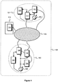
- Fig. 1 shows an example of a communication system 100, to which the equipment according to an embodiment of the invention has been connected for determining a quantity to be measured from said communication system.
- the quantity to be measured may represent, for example, the transmission delay between different parts of a communication system or the phase difference of clock times in different parts of the communication system.
- the first area 101 of the communication system includes the elements 112 and 111, which have been arranged to use the first clock time produced by the first clockwork 107.
- the second area 102 of the communication system includes the elements 108, 109 and 110, which have been arranged to use the second clock time produced by the second clockwork 106.
- the crosshatched ellipse 103 represents the other parts of the communication system.
- the communication system 100 may be a geographically distributed communication network, for example.
- the elements 108 to 112 can be network elements of the communication network, such as routers, switches, hubs or base stations of a mobile phone network.
- the area 101 represents a single network element, such as a router, switch, hub or base station of a mobile phone network.
- the area 102 may represent a single network element.
- the communication system 100 may also be a single device, such as a communication device in the operator's equipment room, which consists of units connected to each other by communication connections, which units in this case represent the elements 108 to 112 of the communication system.
- the equipment for determining a quantity to be measured from the communication system includes a processor system, which includes one or more of the processors 104, 105 and 113 in the embodiment of the invention illustrated in Fig. 1 .
- the processor system may include processors located in different places in the communication system, or the processor system may consist of one or more processors located centrally.
- Fig. 2 is a messaging diagram, which illustrates the operation of equipment according to some embodiments of the invention in a situation presented as an example in a communication system shown in Fig. 1 .
- a plurality of first measurement messages md(1), ..., md(N) are sent from area 101 ( Fig. 1 ) to area 102, and their instants of transmission measured in area 101 are t TX1 (1), ..., t TX1 (N), and the instants of reception measured in area 102 are t RX2 (1), ..., t RX2 (N).
- a second measurement message mg(1) is sent from area 102 to area 101, and possibly one or more third measurement messages mg(2), ..., mg(M), for which the instants of transmission measured in area 102 are t TX2 (1), ..., t TX2 (M), and the instants of reception measured in area 101 are t RX1 (1), ..., t RX1 (M).
- the numbers N and M of measurement messages transferred in different transmission directions may be equal or different.
- the communication system 100 may be a frame switched communication system, in which the measurement messages mentioned above are transmitted in data transmission frames.
- the data transmission frames may be, for instance, IP (Internet Protocol) packages , ATM (Asynchronous Transfer Mode) frames , Ethernet frames, MPLS (Multiprotocol Label Switching) frames, Frame Relay frames or frames of some other data transfer protocol.
- the communication system 100 may also be a time-slot switched communication system, in which said measurement messages may be, for example, bit sequences with a predetermined bit pattern.
- Said processor system is arranged to calculate the values of the time difference E1 for said first measurement messages md(1), ..., md(N).
- Said instant of transmission has been measured according to the clock time produced by the clockwork 107, and said instant of reception has been measured according to the clock time produced by the clockwork 106.
- the processor system is arranged to calculate, on the basis of the values of the time difference, an estimate E1 min of the minimum value of said time difference.
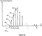
- Fig. 3a illustrates the determination of the estimate E1 min of the minimum value of said time difference.
- the ranges of values need not be of equal length.
- the occurrence frequency indicators of different ranges of values (such as 333, 334 and 335) constitute an estimate of the distribution of the time difference E1.
- Said processor system is arranged to fit a curve 331 to the occurrence frequency indicators of said ranges of values.
- the curve is fitted to the occurrence frequency indicators of the ranges of values representing the lower part of the range of variation of said time difference.
- the curve 331 may be, for example, a polynome, which can be fitted to the values of the occurrence frequency indicators by the least squares method, for example.
- Said processor system is arranged to specify the value of the time difference E1 corresponding to the zero point 332 of the curve 331 as the estimate of the minimum value of the time difference, E1 min .
- the estimate of the minimum value of the time difference E1 min determined from the estimate of the distribution of the time difference does not necessarily correspond to the difference between the instants of reception and transmission of any one of the measurement messages md(1),..., md(N).
- the estimate of the minimum value of the time difference E1 min determined from the estimate of the distribution of the time difference is an approximate value for the difference between the instants of reception and transmission, which would be obtained in a situation in which the transmission delay from area 101 to area 102 is the smallest possible.
- said processor system is arranged to use a part of the graph of function F as said curve, the expression of the function F containing settable parameters, and the function F having the following properties (a) and (b):
- Fig. 3b illustrates the determination of the estimate E1 min of the minimum value of said time difference. Curve 331 represents a part of the graph of function F. From Fig. 3b it is seen that a function having the above mentioned properties (a) and (b) can be used to model the phenomenon occurring especially in heavily loaded communication systems, in which the minimum value of the time difference seldom occurs.
- the rareness of the occurrence of the minimum value of the time difference is indicated by the fact that the derivative of the density function of the time difference with regard to the time difference is very small near the minimum value of the time difference.
- Said processor system is arranged to determine the values of said settable parameters on the basis of said occurrence frequency indicators of the ranges of values (such as 333, 334 and 335) and to set said x0, which corresponds to the zero point 332 of the curve 331, as said estimate of the minimum value of the time difference E1 min .
- the values of said settable parameters can be determined by the least squares method, for example.
- Said processor system is arranged to determine the quantity to be measured from the communication system 100 on the basis of the estimate of the minimum value of said time difference E1 min and the information related to the second measurement message mg(1) ( Fig. 2 ). Said information is based on the instant of transmission t TX2 (1) measured in area 102 and the instant of reception t RX1 (1) measured in area 101 for the measurement message mg(1).
- said processor system is arranged to determine the transmission delay D between area 101 ( Fig. 1 ) and area 102, which in this case represents the quantity to be measured from the communication system 100.
- E1 min is an estimate for the minimum value of the time difference t RX2 - t TX1 , and thus equation (3) corresponds to equation (2), which was presented earlier in this document.
- said processor system is arranged to determine the phase difference ⁇ between the clock times of area 101 ( Fig. 1 ) and area 102, which in this case represents the quantity to be measured from the communication system 100.
- E1 min is an estimate for the minimum value of the time difference t RX2 - t TX1 , and thus equation (4) corresponds to equation (1), which was presented earlier in this document.
- said processor system is arranged to calculate the values of the second time difference E2 for said second measurement message mg(1) ( Fig. 2 ) and at least for one third measurement message mg(2),..., mg(M).
- Said instant of transmission has been measured according to the clock time produced by the clockwork 106, and said instant of reception has been measured according to the clock time produced by the clockwork 107.
- the processor system is arranged to calculate, on the basis of said values of the second time difference, an estimate E2 min of the minimum value of said second time difference.
- Said processor system may be, for example, arranged to select the smallest of said values of the second time difference and to use the selected smallest value of the second time difference as said estimate of the minimum value of the second time difference, E2 min , or said processor system may be arranged to calculate an estimate of the distribution of said second time difference E2 and to determine an estimate E2 min of the minimum value of the second time difference from the estimate of said distribution according to what has been described with reference to Fig.
- Said processor system is arranged to determine the quantity to be measured from the communication system 100 on the basis of the estimate of the minimum value of said time difference E1 min and the estimate of the minimum value of said second time difference E2 min .
- E1 min is an estimate for the minimum value of the time difference t RX2 - t TX1
- E2 min is an estimate for the minimum value of the time difference t RX1 - t TX2
- equation (5) corresponds to equation (2), which was presented earlier in this document.
- E1 min is an estimate for the minimum value of the time difference t RX2 - t TX1
- E2 min is an estimate for the minimum value of the time difference t RX1 - t TX2
- equation (6) corresponds to equation (1), which was presented earlier in this document.
- said processor system is arranged to adjust the clockwork 106 and/or the clockwork 107 on the basis of a quantity measured from the communication network, which is preferably said phase difference ⁇ .
- the operations of the equipment according to the embodiment of the invention can be distributed in many different ways, or said operations can be performed in a centralized manner. It is possible, for example, to transfer the instants of transmission and reception of the measurement messages t TX1 (1), ..., t TX1 (N), t TX2 (1), ..., t TX2 (M), t RX1 (1), ..., t RX1 (M), t RX2 (1), ..., t RX2 (N) ( Fig. 2 ) from areas 101 and 102 to a unit 114 located outside said areas, which unit contains a processor system according to the embodiment of the invention for determining the quantity to be measured from the communication system.
- the processor system located in the unit 114 may consist of one processor 113 or a number of processors connected together. It is also possible that the instants of reception t RX2 (1), ..., t RX2 (N) and instants of transmission t TX2 (1), ..., t TX2 (M) ( Fig. 2 ) measured in area 102 are transferred to area 101, which contains the processor system according to the embodiment of the invention.
- the processor system located in area 101 may consist of one processor 105 or a number of processors connected together. It is also possible that the instants of reception t RX1 (1), ..., t RX1 (M) and instants of transmission t TX1 (1), ..., h X1 (N) ( Fig. 2 ) measured in area 101 are transferred to area 102, which contains the processor system according to the embodiment of the invention.
- the processor system located in area 102 may consist of one processor 104 or a number of processors connected together.
- said processor system includes a processor 105 located in area 101 and a processor 104 located in area 102.
- the processor 104 is arranged to calculate the value of the time difference for each received measurement message md(i) and to calculate the estimate of the minimum value of the time difference E1 min .
- the processor 105 is arranged to instruct the element 111 (or 112) to transmit the instant of reception t RX1 (1) measured in area 101 for the received measurement message mg(1) to area 102.
- the data message DM shown in Fig. 2 depicts the transfer of information indicating said instant of reception t RX1 (1) from area 101 to area 102.
- the processor 104 is arranged to determine the quantity to be measured from the communication system on the basis of the estimate of the minimum value of said time difference E1 min and the instants of transmission and reception, t TX2 (1) and t RX1 (1), of the measurement message mg(1) according to equation (3) and/or equation (4), for example.
- the processor 104 may also be arranged to adjust the clockwork 106 on the basis of said quantity to be measured. In such a situation, the clockwork 107 may function as the master clock, and the clockwork 106 may function as the slave clock, whereby the clock time produced by the slave is synchronized to the clock time produced by the clockwork 107.
- said processor system includes a processor 105 located in area 101 and a processor 104 located in area 102.
- the processors 104 and 105 or the communication system 100 are arranged to write in each measurement message the instant of transmission of the measurement message, which has been measured at the location of transmission of the measurement message in question.
- the processor 104 is arranged to calculate the value of the time difference for each received measurement message md(i) and to calculate the estimate of the minimum value of the time difference E1 min .
- the processor 105 is arranged to calculate the value of the second time difference for each received measurement message mg(j) and to calculate the estimate of the minimum value of the second time difference E2 min .
- the processor 105 is arranged to instruct the element 111 (or 112) to transmit said estimate of the minimum value of the second time difference E2 min to area 102.
- the processor 104 is arranged to determine the quantity to be measured from the communication system on the basis of the estimate E1 min of the minimum value of said time difference and the estimate E1 min of the minimum value of said second time difference according to equation (5) and/or equation (6), for example.
- the processor 104 may also be arranged to adjust the clockwork 106 on the basis of said quantity to be measured.
- Fig. 4 shows a network element 400 according to an embodiment of the invention, which may be, for example, an IP (Internet Protocol) router, an MPLS (Multiprotocol Label Switching) switch, an ATM (Asynchronous Transfer Mode) switch, an Ethernet switch or a combination of one or more of those mentioned above.
- the network element includes a transmitter 441 for transmitting digital data to the communication system 403, and a receiver 442 for receiving digital data from said communication system.
- the network element includes the equipment 440 according to the embodiment of the invention for determining the quantity to be measured.
- the quantity to be measured may represent, for example, data transmission delay between the network element and a second network element belonging to the communication system 403, or the phase difference between the clock times of the network element and said second network element.
- the equipment 440 includes a processor system that consists of one or more processors. Said processor system is arranged to calculate the values of the time difference for measurement messages, which have been received in the network element. The value of said time difference related to each measurement message is essentially the difference between the instant of reception measured in the network element and the instant of transmission measured in the communication system 403 for the measurement message in question.
- the receiver 442 is arranged to receive the data that indicate the instants of transmission of the measurement messages received in the network element.
- the unit 443 is arranged to read said instants of transmission from the received data. For example, each received measurement message may include information that indicates the instant of transmission of the measurement message in question.
- Said processor system is arranged:
- Said processor system is arranged to determine said quantity to be measured on the basis of an estimate of the minimum value of said time difference and the information related to one or more measurement message(s) transmitted from the network element. Said information is based on the instant of transmission measured in the network element and the instant of reception measured in the communication system 403 for one or more transmitted measurement message(s).
- the receiver 442 is arranged to receive information related to said instant of reception, and the unit 443 is arranged to read said information from the received data.
- the receiver 442 is arranged to receive the information that indicates the instants of reception measured in the communication system 403 for the measurement messages transmitted from the network element, and the unit 443 is arranged to read said instants of reception from the received data.
- the processor system of the equipment 440 is arranged to calculate the values of the second time difference for at least two measurement messages transmitted from the network element.
- the value of said second time difference related to each transmitted measurement message is essentially the difference between the instant of reception measured in the communication system 403 and the instant of transmission measured in the network element for the measurement message in question.
- the processor system is arranged to calculate, on the basis of said values of the second time difference, an estimate of the minimum value of said second time difference.
- Said processor system is arranged to determine the quantity to be measured on the basis of the estimate of the minimum value of said time difference and the estimate of the minimum value of said second time difference.
- the receiver 442 is arranged to receive an estimate of the minimum value of the second time difference, which has been calculated for the measurement messages transmitted from the network element, and the unit 443 is arranged to read said estimate of the minimum value of the second time difference from the received data.
- the processor system of the equipment 440 is arranged to determine said quantity to be measured on the basis of the estimate of the minimum value of said time difference and the estimate of the minimum value of said second time difference.
- the network element includes an adjustment unit 444, which is arranged to adjust the clockwork 406 in the network element on the basis of said quantity to be measured.
- the transmitter 441 is arranged to transmit data transmission frames to the communication system 403
- the receiver 442 is arranged to receive data transmission frames from the communication system
- the unit 443 is arranged to read from the received data transmission frame the instant of transmission measured for the data transmission frame in the communication system 403.
- Fig. 5 is a flow chart of a method according to an embodiment of the invention for determining a quantity to be measured from the communication system.
- the quantity to be measured may represent, for example, data transmission delay or phase difference between clock times.
- the first measurement messages M(AB) are transmitted from the first area A of said communication system to the second area B of said communication system.
- the second measurement message M(BA) is transmitted from said second area B to said first area A.
- the values of the time difference are calculated for said first measurement messages M(AB).
- the value of said time difference relating to each measurement message is essentially the difference between the instant of reception measured in said second area B and the instant of transmission measured in the first area A for the measurement message in question.
- an estimate E1 min of the minimum value of said time difference is calculated on the basis of said values of the time difference as follows:
- step 505 said quantity to be measured is determined on the basis of the estimate of the minimum value of said time difference E1 min and the information related to said second measurement message M(BA), said information being based on the instant of transmission measured in said second region B and the instant of reception measured in said first region A for said second measurement message.
- said curve is a part of the graph of function F, which is preferably a function of one variable, the expression of function F containing settable parameters, and function F having the following properties:
- the values of said settable parameters are determined on the basis of the occurrence frequency indicators of said ranges of values, and said x0 is set as said estimate of the minimum value of the time difference E1 min .
- the values of said settable parameters can be determined by the least squares method, for example.
- Fig. 6 is a flow chart of a method according to another embodiment of the invention for determining a quantity to be measured from the communication system.
- the first measurement messages M(AB) are transmitted from the first area A of said communication system to the second area B of said communication system.
- a second measurement message and at least one third measurement message M(BA) are transmitted from said second area B to said first area A.
- the values of the time difference are calculated for said first measurement messages M(AB).
- the value of said time difference relating to each measurement message is essentially the difference between the instant of reception measured in said second area B and the instant of transmission measured in the first area A for the measurement message in question.
- the values of the second time difference are calculated for said second measurement message and at least one third measurement message M(BA).
- the value of said second time difference relating to each measurement message is essentially the difference between the instant of reception measured in said first area A and the instant of transmission measured in the second area B for the measurement message in question.
- an estimate E1 min of the minimum value of said time difference is calculated on the basis of said values of the time difference.
- an estimate E2 min of the minimum value of said second time difference is calculated on the basis of said values of the second time difference.
- said quantity to be measured is determined on the basis of an estimate of the minimum value of said time difference E1 min and an estimate of the minimum value of said second time difference E2 min .
- the smallest of said values of the second time difference is selected, and the selected, smallest value of the second time difference is used as said estimate of the minimum value of the second time difference E2 min .
- said estimate of the minimum value of the second time difference E2 min is calculated as follows:
- the measurement messages are in the form of one of the alternatives: IP (Internet Protocol) packets, ATM (Asynchronous Transfer Mode) frames, Ethernet frames, MPLS (Multiprotocol Label Switching) frames, and Frame Relay frames.
- IP Internet Protocol
- ATM Asynchronous Transfer Mode
- Ethernet Ethernet frames
- MPLS Multiprotocol Label Switching
- the measurement messages are bit sequences with a predetermined bit pattern.
- the computer program according to an embodiment of the invention is saved in a storage means readable by the processing unit, such as an optical disk (CD, Compact Disk).
- a storage means readable by the processing unit such as an optical disk (CD, Compact Disk).
- the computer program according to an embodiment of the invention is encoded to a signal, which can be received from a communication network, such as the Internet.
Landscapes
- Engineering & Computer Science (AREA)
- Computer Networks & Wireless Communication (AREA)
- Signal Processing (AREA)
- Environmental & Geological Engineering (AREA)
- Data Exchanges In Wide-Area Networks (AREA)
- Monitoring And Testing Of Transmission In General (AREA)
Claims (15)
- Einrichtung zum Bestimmen einer von einem Kommunikationssystem (100) zu messenden Größe, welche Einrichtung ein Prozessorsystem (104, 105) umfasst, welches dazu eingerichtet ist, Werte einer Zeitdifferenz für erste Messungsnachrichten zu berechnen, welche von einem ersten Bereich (101) des Kommunikationssystems zu einem zweiten Bereich (102) des Kommunikationssystems übertragen worden sind, wobei der Wert der Zeitdifferenz, welche sich auf jede erste Messungsnachricht bezieht, eine Differenz zwischen einem in dem zweiten Bereich gemessenen Empfangsaugenblick und einem in dem ersten Bereich gemessenen Übertragungsaugenblick für die betreffende Messungsnachricht ist, dadurch gekennzeichnet, dass das Prozessorsystem auch dazu eingerichtet ist:- die Werte der Zeitdifferenz in Wertebereiche zu klassifizieren, welche vorbestimmte untere und obere Grenzen aufweisen,- für jeden Wertebereich einen Auftrittshäufigkeitsindikator (333, 334, 335) zu berechnen, welcher proportional ist zu der Anzahl von zu dem Wertebereich gehörenden Werten der Zeitdifferenz,- eine Kurve (331) an die Auftrittshäufigkeitsindikatoren der Wertebereiche anzupassen,- auf der Basis der Kurve eine Abschätzung des Minimalwerts der Zeitdifferenz zu bestimmen und- die zu messende Größe auf der Basis der Abschätzung des Minimalwerts der Zeitdifferenz und einer sich auf eine zweite Messungsnachricht beziehende Information zu bestimmen, welche zweite Messungsnachricht von dem zweiten Bereich (102) zu dem ersten Bereich (101) gesendet worden ist und welche Information auf einem in dem zweiten Bereich gemessenen Übertragungsaugenblick und einem in dem ersten Bereich gemessenen Empfangsaugenblick für die zweite Messungsnachricht basiert.
- Einrichtung nach Anspruch 1, wobei das Prozessorsystem dazu eingerichtet ist:- Werte einer zweiten Zeitdifferenz für die zweite Messungsnachricht und wenigstens eine dritte Messungsnachricht zu berechnen, welche von dem zweiten Bereich zu dem ersten Bereich übertragen worden ist, wobei der Wert der zweiten Zeitdifferenz, welche sich auf jede Messungsnachricht bezieht, eine Differenz zwischen einem in dem ersten Bereich gemessenen Empfangsaugenblick und einem in dem zweiten Bereich gemessenen Übertragungsaugenblick für die betreffende Messungsnachricht ist,- eine Abschätzung des Minimalwerts der zweiten Zeitdifferenz auf der Basis der Werte der zweiten Zeitdifferenz zu berechnen und- die zu messende Größe auf der Basis der Abschätzung des Minimalwerts der Zeitdifferenz und der Abschätzung des Minimalwerts der zweiten Zeitdifferenz zu bestimmen.
- Einrichtung nach Anspruch 1, wobei die zu messende Größe eine Übertragungsverzögerung D zwischen dem ersten Bereich und dem zweiten Bereich ist und das Prozessorsystem dazu eingerichtet ist, die zu messende Größe zu bestimmen, durch die Gleichung:

- Einrichtung nach Anspruch 1, wobei die zu messende Größe eine Phasendifferenz Ψ zwischen gebrauchten Zeiten des ersten Bereichs und des zweiten Bereichs ist und das Prozessorsystem dazu eingerichtet ist, die zu messende Größe zu bestimmen, durch die Gleichung:

- Einrichtung nach Anspruch 2, wobei die zu messende Größe eine Übertragungsverzögerung D zwischen dem ersten Bereich und dem zweiten Bereich ist und das Prozessorsystem dazu eingerichtet ist, die zu messende Größe zu bestimmen, durch die Gleichung:

- Einrichtung nach Anspruch 2, wobei die zu messende Größe eine Phasendifferenz Ψ zwischen gebrauchten Zeiten des ersten Bereichs und des zweiten Bereichs ist und das Prozessorsystem dazu eingerichtet ist, die zu messende Größe zu bestimmen, durch die Gleichung:

- Einrichtung nach Anspruch 2, wobei das Prozessorsystem dazu eingerichtet ist, den kleinsten der Werte der zweiten Zeitdifferenz auszuwählen und den ausgewählten kleinsten Wert der zweiten Zeitdifferenz als die Abschätzung des Minimalwerts der zweiten Zeitdifferenz zu verwenden.
- Einrichtung nach Anspruch 2, wobei das Prozessorsystem dazu eingerichtet ist:- die Werte der zweiten Zeitdifferenz in Wertebereiche mit vorbestimmten unteren und oberen Grenzen zu klassifizieren,- für jeden Wertebereich einen zweiten Auftrittshäufigkeitsindikator zu berechnen, welcher proportional ist zu der Anzahl von zu dem Wertebereich gehörenden Werten der zweiten Zeitdifferenz,- eine zweite Kurve an die Auftrittshäufigkeitsindikatoren der Wertebereiche anzupassen und- auf der Basis der zweiten Kurve eine Abschätzung des Minimalwerts der zweiten Zeitdifferenz zu bestimmen.
- Einrichtung nach Anspruch 1, wobei die ersten Messungsnachrichten und die zweite Messungsnachricht einer der folgenden Alternativen entsprechen: IP-(Internet Protocol) Pakete, ATM- (Asynchronous Transfer Mode) Frames, Ethernet-Frames, MPLS- (Multiprotocol Label Switching) Frames und Frame-Relay-Frames.
- Einrichtung nach Anspruch 1, wobei die ersten Messungsnachrichten und die zweite Messungsnachricht Bitsequenzen mit einem vorbestimmten Bitmuster sind.
- Einrichtung nach Anspruch 1, wobei das Prozessorsystem dazu eingerichtet ist, einen Teil des Graphen einer Funktion F als die Kurve zu verwenden, wobei der Ausdruck der Funktion F einstellbare Parameter enthält und die Funktion F die folgenden Eigenschaften aufweist:- es gibt eine reelle Zahl x0, mit welcher sowohl die Funktion F als auch die Ableitung F' der Funktion Null sind und deren Wert wenigstens von einem der einstellbaren Parameter abhängig ist, und- es gibt eine reelle Zahl x1 > x0, mit welcher sowohl die Ableitung F' als auch die zweite Ableitung F" der Funktion in einem offenen Bereich von x0 bis x1 positiv sind, unddas Prozessorsystem dazu eingerichtet ist, die Werte der einstellbaren Parameter auf der Basis der Auftrittshäufigkeitsindikatoren der Wertebereiche (333, 334, 335) zu bestimmen und x0 als die Abschätzung des Minimalwerts der Zeitdifferenz zu setzen.
- Netzwerkelement, welches einen Sender (441) zum Übertragen digitaler Daten zu einem Kommunikationssystem und einen Empfänger (442) zum Empfangen digitaler Daten von dem Kommunikationssystem aufweist, wobei das Netzwerkelement eine Einrichtung (440) nach Anspruch 1 zum Bestimmen einer von dem Kommunikationssystem zu messenden Größe umfasst.
- Netzwerkelement nach Anspruch 12, wobei das Netzwerkelement eine Einstelleinheit (444) umfasst, welche dazu eingerichtet ist, ein Uhrwerk (406) in dem Netzwerkelement auf der Basis der zu messenden Größe einzustellen.
- Verfahren zum Bestimmen einer von einem Kommunikationssystem zu messenden Größe, welches Verfahren umfasst:- Übertragen (501, 601) erster Messungsnachrichten von einem ersten Bereich des Kommunikationssystems zu einem zweiten Bereich des Kommunikationssystems,- Senden (502, 602) einer zweiten Messungsnachricht von dem zweiten Bereich zu dem ersten Bereich und- Berechnen (503, 603) von Werten einer Zeitdifferenz für die ersten Messungsnachrichten, wobei der Wert der Zeitdifferenz, welche sich auf jede erste Messung bezieht, eine Differenz zwischen einem in dem zweiten Bereich gemessenen Empfangsaugenblick und einem in dem ersten Bereich gemessenen Übertragungsaugenblick für die betreffende Messungsnachricht ist,dadurch gekennzeichnet, dass das Verfahren auch umfasst:- Klassifizieren (504, 604) der Werte der Zeitdifferenz in Wertebereiche, welche vorbestimmte untere und obere Grenzen aufweisen,- Berechnen (504, 604) für jeden Wertebereich eines Auftrittshäufigkeitsindikators (333, 334, 335), welcher proportional ist zu der Anzahl von zu dem Wertebereich gehörenden Werten der Zeitdifferenz,- Anpassen (504, 604) einer Kurve (331) an die Auftrittshäufigkeitsindikatoren der Wertebereiche,- Bestimmen (504, 604) auf der Basis der Kurve einer Abschätzung des Minimalwerts der Zeitdifferenz und- Bestimmen (505, 605) der messbaren Größe auf der Basis der Abschätzung des Minimalwerts der Zeitdifferenz und der sich auf die zweite Messungsnachricht beziehenden Information, wobei die Information auf einem in dem zweiten Bereich gemessenen Übertragungsaugenblick und einem in dem ersten Bereich gemessenen Empfangsaugenblick für die zweite Messungsnachricht basiert.
- Computerprogramm zum Bestimmen einer von einem Kommunikationssystem zu messenden Größe, welches Computerprogramm Anweisungen, welche durch einen programmierbaren Prozessor ausführbar sind, zum Anweisen des programmierbaren Prozessors, Werte einer Zeitdifferenz für erste Messungsnachrichten zu berechnen, welche von einem ersten Bereich des Kommunikationssystems zu einem zweiten Bereich des Kommunikationssystems übertragen worden sind, umfasst, wobei der Wert der Zeitdifferenz, welche sich auf jede erste Messungsnachricht bezieht, eine Differenz zwischen einem in dem zweiten Bereich gemessenen Empfangsaugenblick und einem in dem ersten Bereich gemessenen Übertragungsaugenblick für die betreffende Messungsnachricht ist, dadurch gekennzeichnet, dass das Computerprogramm Anweisungen, welche durch den programmierbaren Prozessor ausführbar sind, umfasst:- den programmierbaren Prozessor anzuweisen, die Werte der Zeitdifferenz in Wertebereiche zu klassifizieren, welche vorbestimmte untere und obere Grenzen aufweisen,- den programmierbaren Prozessor anzuweisen, für jeden Wertebereich einen Auftrittshäufigkeitsindikator (333, 334, 335) zu berechnen, welcher proportional ist zu der Anzahl von zu dem Wertebereich gehörenden Werten der Zeitdifferenz,- den programmierbaren Prozessor anzuweisen, eine Kurve (331) an die Auftrittshäufigkeitsindikatoren der Wertebereiche anzupassen,- den programmierbaren Prozessor anzuweisen, auf der Basis der Kurve eine Abschätzung des Minimalwerts der Zeitdifferenz zu bestimmen, und- den programmierbaren Prozessor anzuweisen, die zu messende Größe auf der Basis der Abschätzung des Minimalwerts der Zeitdifferenz und einer sich auf eine zweite Messungsnachricht beziehende Information zu bestimmen, welche zweite Messungsnachricht von dem zweiten Bereich zu dem ersten Bereich gesendet worden ist und welche Information auf einem in dem zweiten Bereich gemessenen Übertragungsaugenblick und einem in dem ersten Bereich gemessenen Empfangsaugenblick für die zweite Messungsnachricht basiert.
Applications Claiming Priority (1)
| Application Number | Priority Date | Filing Date | Title |
|---|---|---|---|
| FI20085525A FI122945B (fi) | 2008-05-30 | 2008-05-30 | Menetelmä ja laitteisto mittauksia varten |
Publications (3)
| Publication Number | Publication Date |
|---|---|
| EP2129016A2 EP2129016A2 (de) | 2009-12-02 |
| EP2129016A3 EP2129016A3 (de) | 2017-05-17 |
| EP2129016B1 true EP2129016B1 (de) | 2018-05-02 |
Family
ID=39523176
Family Applications (1)
| Application Number | Title | Priority Date | Filing Date |
|---|---|---|---|
| EP09160993.3A Active EP2129016B1 (de) | 2008-05-30 | 2009-05-25 | Verfahren und Vorrichtung zur Messung der Verzögerung in einem Nachrichtenübertragungssystem |
Country Status (4)
| Country | Link |
|---|---|
| US (1) | US7864813B2 (de) |
| EP (1) | EP2129016B1 (de) |
| CN (1) | CN101594169B (de) |
| FI (1) | FI122945B (de) |
Families Citing this family (9)
| Publication number | Priority date | Publication date | Assignee | Title |
|---|---|---|---|---|
| FI120284B (fi) * | 2007-07-20 | 2009-08-31 | Tellabs Oy | Huojuntapuskurin täyttöasteen säätö |
| DE112010004514B4 (de) * | 2009-11-20 | 2021-01-07 | Keysight Technologies Singapore (Sales) Pte. Ltd. | Verfahren,System und Computerprogrammprodukt zum Messen einer Datenübertragung von einem ersten Gerät zu einem zweiten Gerät |
| GB2508769B (en) * | 2011-12-05 | 2014-10-22 | Ibm | Simulation execution method, program and system |
| DE112012006890B4 (de) * | 2012-09-11 | 2020-03-26 | Mitsubishi Electric Corporation | Korrekturparameterberechnungsgerät, System, Korrekturparameterberechnungsverfahren, und Computerprogramm |
| EP2736194B1 (de) * | 2012-11-27 | 2017-09-27 | ADVA Optical Networking SE | Latenzüberwachungspunkt |
| CN104767650A (zh) * | 2014-01-03 | 2015-07-08 | 中国移动通信集团广东有限公司 | 一种消息网络延迟测算方法及装置 |
| JP6523058B2 (ja) * | 2015-06-05 | 2019-05-29 | 株式会社東芝 | 通信システムおよび推定方法 |
| CN109802898B (zh) * | 2019-02-01 | 2022-08-09 | 深圳市比速智网技术有限公司 | 多链路数据传输方法、接收装置及存储介质 |
| US11516151B2 (en) | 2019-12-31 | 2022-11-29 | Infinera Oy | Dynamically switching queueing systems for network switches |
Family Cites Families (9)
| Publication number | Priority date | Publication date | Assignee | Title |
|---|---|---|---|---|
| US6335927B1 (en) * | 1996-11-18 | 2002-01-01 | Mci Communications Corporation | System and method for providing requested quality of service in a hybrid network |
| US6327274B1 (en) * | 1998-09-15 | 2001-12-04 | Nokia Telecommunications, Inc. | Method for estimating relative skew between clocks in packet networks |
| US6661810B1 (en) * | 1999-03-19 | 2003-12-09 | Verizon Laboratories Inc. | Clock skew estimation and removal |
| GB2399263A (en) | 2003-03-07 | 2004-09-08 | Zarlink Semiconductor Ltd | Clock synchronisation over a packet network |
| US7415044B2 (en) | 2003-08-22 | 2008-08-19 | Telefonaktiebolaget Lm Ericsson (Publ) | Remote synchronization in packet-switched networks |
| CN1642055A (zh) * | 2004-01-17 | 2005-07-20 | 华为技术有限公司 | Wcdma通信系统中的移动台观测时间差测量方法 |
| EP1785802A1 (de) | 2005-11-10 | 2007-05-16 | ETH Zürich, ETH Transfer | Verfahren zur Frequenzsynchronisation |
| KR20080082891A (ko) * | 2007-03-09 | 2008-09-12 | 한국전자통신연구원 | Ofdma 시스템에서 부채널 할당 방법 및 그 장치 |
| US7962091B2 (en) * | 2008-03-14 | 2011-06-14 | Intel Corporation | Resource management and interference mitigation techniques for relay-based wireless networks |
-
2008
- 2008-05-30 FI FI20085525A patent/FI122945B/fi not_active IP Right Cessation
-
2009
- 2009-05-25 EP EP09160993.3A patent/EP2129016B1/de active Active
- 2009-05-31 CN CN200910142619.5A patent/CN101594169B/zh active Active
- 2009-06-01 US US12/475,985 patent/US7864813B2/en active Active
Non-Patent Citations (1)
| Title |
|---|
| None * |
Also Published As
| Publication number | Publication date |
|---|---|
| CN101594169A (zh) | 2009-12-02 |
| FI20085525A0 (fi) | 2008-05-30 |
| CN101594169B (zh) | 2014-09-10 |
| US20090296795A1 (en) | 2009-12-03 |
| FI122945B (fi) | 2012-09-14 |
| EP2129016A3 (de) | 2017-05-17 |
| FI20085525L (fi) | 2009-12-01 |
| EP2129016A2 (de) | 2009-12-02 |
| US7864813B2 (en) | 2011-01-04 |
Similar Documents
| Publication | Publication Date | Title |
|---|---|---|
| EP2129016B1 (de) | Verfahren und Vorrichtung zur Messung der Verzögerung in einem Nachrichtenübertragungssystem | |
| KR101481396B1 (ko) | 노드들 사이의 집성된 연결을 갖는 패킷-스위칭된 네트워크의 마스터 및 슬레이브 클록들을 동기화시키기 위한 방법 및 관련된 동기화 디바이스들 | |
| EP2434673B1 (de) | Netzwerksynchronisationsverfahren und vorrichtung zum durchführen von zeitsynchronisation zwischen knoten | |
| EP2813016B1 (de) | Taktsynchronisierung anhand von mehreren netzwerkpfaden | |
| US9537648B2 (en) | Data transmission over packet switched network | |
| EP3202062B1 (de) | Verteilung von informationen zur dynamischen genauigkeit in einem netzwerk von ieee-1588-takten | |
| JP7283069B2 (ja) | 時刻同期経路選択装置、および、時刻同期経路選択方法 | |
| EP1931084B1 (de) | Verfahren zum erhalten der streckenschätzungsparameter | |
| CN104737490A (zh) | 通信装置、通信系统和时刻同步方法 | |
| KR20140111011A (ko) | 시간-인식 디바이스들 사이에 시간 정보를 통신하는 방법 및 장치 | |
| EP2658161B1 (de) | Sendevorrichtung, sendeverfahren und computerprogramm | |
| EP2209239B1 (de) | Verfahren und Vorrichtung zur Abstimmung eines Signaltaktes | |
| CN101499936B (zh) | 用于确定传输延迟差的方法和设置 | |
| US9213317B2 (en) | Method and arrangement for transferring a time of day value between network elements | |
| JP2007134873A (ja) | 高精度時刻同期処理装置およびそのプログラム,ならびにネットワーク混雑度警告装置およびそのプログラム | |
| JP4815534B2 (ja) | パケット遅延特性計測装置及び方法 | |
| EP3812716B1 (de) | Dynamische wägevorrichtung | |
| JP6573328B2 (ja) | 無線通信システム及び無線通信装置 | |
| US8806261B2 (en) | Method and a device for controlling a clock signal generator | |
| JP4536026B2 (ja) | ネットワーク品質測定方法、測定装置及びプログラム | |
| KR20150016735A (ko) | 중앙 집중 제어 평면을 이용한 네트워크 시각 동기 시스템 | |
| EP1777854B1 (de) | Vorrichtung und Verfahren zur Systemparameteranpassung für funkbasierte Kommunikationssysteme | |
| EP4391425A1 (de) | Kommunikationsvorrichtung, steuerungsverfahren dafür und computerprogramm | |
| US20250023705A1 (en) | Clock synchronization between networked devices based on packet congestion information | |
| US20230254229A1 (en) | Network delay estimation |
Legal Events
| Date | Code | Title | Description |
|---|---|---|---|
| PUAI | Public reference made under article 153(3) epc to a published international application that has entered the european phase |
Free format text: ORIGINAL CODE: 0009012 |
|
| AK | Designated contracting states |
Kind code of ref document: A2 Designated state(s): AT BE BG CH CY CZ DE DK EE ES FI FR GB GR HR HU IE IS IT LI LT LU LV MC MK MT NL NO PL PT RO SE SI SK TR |
|
| RAP1 | Party data changed (applicant data changed or rights of an application transferred) |
Owner name: CORIANT OY |
|
| PUAL | Search report despatched |
Free format text: ORIGINAL CODE: 0009013 |
|
| AK | Designated contracting states |
Kind code of ref document: A3 Designated state(s): AT BE BG CH CY CZ DE DK EE ES FI FR GB GR HR HU IE IS IT LI LT LU LV MC MK MT NL NO PL PT RO SE SI SK TR |
|
| RIC1 | Information provided on ipc code assigned before grant |
Ipc: H04J 3/06 20060101AFI20170410BHEP Ipc: H04L 12/26 20060101ALI20170410BHEP |
|
| 17P | Request for examination filed |
Effective date: 20171106 |
|
| RBV | Designated contracting states (corrected) |
Designated state(s): AT BE BG CH CY CZ DE DK EE ES FI FR GB GR HR HU IE IS IT LI LT LU LV MC MK MT NL NO PL PT RO SE SI SK TR |
|
| GRAP | Despatch of communication of intention to grant a patent |
Free format text: ORIGINAL CODE: EPIDOSNIGR1 |
|
| INTG | Intention to grant announced |
Effective date: 20180208 |
|
| GRAS | Grant fee paid |
Free format text: ORIGINAL CODE: EPIDOSNIGR3 |
|
| GRAA | (expected) grant |
Free format text: ORIGINAL CODE: 0009210 |
|
| AK | Designated contracting states |
Kind code of ref document: B1 Designated state(s): AT BE BG CH CY CZ DE DK EE ES FI FR GB GR HR HU IE IS IT LI LT LU LV MC MK MT NL NO PL PT RO SE SI SK TR |
|
| REG | Reference to a national code |
Ref country code: GB Ref legal event code: FG4D |
|
| REG | Reference to a national code |
Ref country code: CH Ref legal event code: EP Ref country code: AT Ref legal event code: REF Ref document number: 996343 Country of ref document: AT Kind code of ref document: T Effective date: 20180515 |
|
| REG | Reference to a national code |
Ref country code: FR Ref legal event code: PLFP Year of fee payment: 10 |
|
| REG | Reference to a national code |
Ref country code: DE Ref legal event code: R096 Ref document number: 602009052063 Country of ref document: DE |
|
| REG | Reference to a national code |
Ref country code: IE Ref legal event code: FG4D |
|
| PGFP | Annual fee paid to national office [announced via postgrant information from national office to epo] |
Ref country code: FR Payment date: 20180522 Year of fee payment: 10 |
|
| REG | Reference to a national code |
Ref country code: NL Ref legal event code: MP Effective date: 20180502 |
|
| REG | Reference to a national code |
Ref country code: LT Ref legal event code: MG4D |
|
| PG25 | Lapsed in a contracting state [announced via postgrant information from national office to epo] |
Ref country code: BG Free format text: LAPSE BECAUSE OF FAILURE TO SUBMIT A TRANSLATION OF THE DESCRIPTION OR TO PAY THE FEE WITHIN THE PRESCRIBED TIME-LIMIT Effective date: 20180802 Ref country code: NO Free format text: LAPSE BECAUSE OF FAILURE TO SUBMIT A TRANSLATION OF THE DESCRIPTION OR TO PAY THE FEE WITHIN THE PRESCRIBED TIME-LIMIT Effective date: 20180802 Ref country code: FI Free format text: LAPSE BECAUSE OF FAILURE TO SUBMIT A TRANSLATION OF THE DESCRIPTION OR TO PAY THE FEE WITHIN THE PRESCRIBED TIME-LIMIT Effective date: 20180502 Ref country code: ES Free format text: LAPSE BECAUSE OF FAILURE TO SUBMIT A TRANSLATION OF THE DESCRIPTION OR TO PAY THE FEE WITHIN THE PRESCRIBED TIME-LIMIT Effective date: 20180502 Ref country code: SE Free format text: LAPSE BECAUSE OF FAILURE TO SUBMIT A TRANSLATION OF THE DESCRIPTION OR TO PAY THE FEE WITHIN THE PRESCRIBED TIME-LIMIT Effective date: 20180502 Ref country code: LT Free format text: LAPSE BECAUSE OF FAILURE TO SUBMIT A TRANSLATION OF THE DESCRIPTION OR TO PAY THE FEE WITHIN THE PRESCRIBED TIME-LIMIT Effective date: 20180502 |
|
| PG25 | Lapsed in a contracting state [announced via postgrant information from national office to epo] |
Ref country code: LV Free format text: LAPSE BECAUSE OF FAILURE TO SUBMIT A TRANSLATION OF THE DESCRIPTION OR TO PAY THE FEE WITHIN THE PRESCRIBED TIME-LIMIT Effective date: 20180502 Ref country code: NL Free format text: LAPSE BECAUSE OF FAILURE TO SUBMIT A TRANSLATION OF THE DESCRIPTION OR TO PAY THE FEE WITHIN THE PRESCRIBED TIME-LIMIT Effective date: 20180502 Ref country code: HR Free format text: LAPSE BECAUSE OF FAILURE TO SUBMIT A TRANSLATION OF THE DESCRIPTION OR TO PAY THE FEE WITHIN THE PRESCRIBED TIME-LIMIT Effective date: 20180502 Ref country code: GR Free format text: LAPSE BECAUSE OF FAILURE TO SUBMIT A TRANSLATION OF THE DESCRIPTION OR TO PAY THE FEE WITHIN THE PRESCRIBED TIME-LIMIT Effective date: 20180803 |
|
| REG | Reference to a national code |
Ref country code: CH Ref legal event code: PL |
|
| REG | Reference to a national code |
Ref country code: AT Ref legal event code: MK05 Ref document number: 996343 Country of ref document: AT Kind code of ref document: T Effective date: 20180502 |
|
| PG25 | Lapsed in a contracting state [announced via postgrant information from national office to epo] |
Ref country code: PT Free format text: LAPSE BECAUSE OF FAILURE TO SUBMIT A TRANSLATION OF THE DESCRIPTION OR TO PAY THE FEE WITHIN THE PRESCRIBED TIME-LIMIT Effective date: 20180903 |
|
| REG | Reference to a national code |
Ref country code: BE Ref legal event code: MM Effective date: 20180531 |
|
| PG25 | Lapsed in a contracting state [announced via postgrant information from national office to epo] |
Ref country code: EE Free format text: LAPSE BECAUSE OF FAILURE TO SUBMIT A TRANSLATION OF THE DESCRIPTION OR TO PAY THE FEE WITHIN THE PRESCRIBED TIME-LIMIT Effective date: 20180502 Ref country code: PL Free format text: LAPSE BECAUSE OF FAILURE TO SUBMIT A TRANSLATION OF THE DESCRIPTION OR TO PAY THE FEE WITHIN THE PRESCRIBED TIME-LIMIT Effective date: 20180502 Ref country code: DK Free format text: LAPSE BECAUSE OF FAILURE TO SUBMIT A TRANSLATION OF THE DESCRIPTION OR TO PAY THE FEE WITHIN THE PRESCRIBED TIME-LIMIT Effective date: 20180502 Ref country code: RO Free format text: LAPSE BECAUSE OF FAILURE TO SUBMIT A TRANSLATION OF THE DESCRIPTION OR TO PAY THE FEE WITHIN THE PRESCRIBED TIME-LIMIT Effective date: 20180502 Ref country code: AT Free format text: LAPSE BECAUSE OF FAILURE TO SUBMIT A TRANSLATION OF THE DESCRIPTION OR TO PAY THE FEE WITHIN THE PRESCRIBED TIME-LIMIT Effective date: 20180502 Ref country code: CZ Free format text: LAPSE BECAUSE OF FAILURE TO SUBMIT A TRANSLATION OF THE DESCRIPTION OR TO PAY THE FEE WITHIN THE PRESCRIBED TIME-LIMIT Effective date: 20180502 Ref country code: SK Free format text: LAPSE BECAUSE OF FAILURE TO SUBMIT A TRANSLATION OF THE DESCRIPTION OR TO PAY THE FEE WITHIN THE PRESCRIBED TIME-LIMIT Effective date: 20180502 |
|
| REG | Reference to a national code |
Ref country code: DE Ref legal event code: R097 Ref document number: 602009052063 Country of ref document: DE |
|
| REG | Reference to a national code |
Ref country code: IE Ref legal event code: MM4A |
|
| PG25 | Lapsed in a contracting state [announced via postgrant information from national office to epo] |
Ref country code: IT Free format text: LAPSE BECAUSE OF FAILURE TO SUBMIT A TRANSLATION OF THE DESCRIPTION OR TO PAY THE FEE WITHIN THE PRESCRIBED TIME-LIMIT Effective date: 20180502 Ref country code: CH Free format text: LAPSE BECAUSE OF NON-PAYMENT OF DUE FEES Effective date: 20180531 Ref country code: LI Free format text: LAPSE BECAUSE OF NON-PAYMENT OF DUE FEES Effective date: 20180531 |
|
| PLBE | No opposition filed within time limit |
Free format text: ORIGINAL CODE: 0009261 |
|
| STAA | Information on the status of an ep patent application or granted ep patent |
Free format text: STATUS: NO OPPOSITION FILED WITHIN TIME LIMIT |
|
| PG25 | Lapsed in a contracting state [announced via postgrant information from national office to epo] |
Ref country code: LU Free format text: LAPSE BECAUSE OF NON-PAYMENT OF DUE FEES Effective date: 20180525 Ref country code: MC Free format text: LAPSE BECAUSE OF FAILURE TO SUBMIT A TRANSLATION OF THE DESCRIPTION OR TO PAY THE FEE WITHIN THE PRESCRIBED TIME-LIMIT Effective date: 20180502 |
|
| 26N | No opposition filed |
Effective date: 20190205 |
|
| GBPC | Gb: european patent ceased through non-payment of renewal fee |
Effective date: 20180802 |
|
| PG25 | Lapsed in a contracting state [announced via postgrant information from national office to epo] |
Ref country code: IE Free format text: LAPSE BECAUSE OF NON-PAYMENT OF DUE FEES Effective date: 20180525 |
|
| PG25 | Lapsed in a contracting state [announced via postgrant information from national office to epo] |
Ref country code: SI Free format text: LAPSE BECAUSE OF FAILURE TO SUBMIT A TRANSLATION OF THE DESCRIPTION OR TO PAY THE FEE WITHIN THE PRESCRIBED TIME-LIMIT Effective date: 20180502 Ref country code: BE Free format text: LAPSE BECAUSE OF NON-PAYMENT OF DUE FEES Effective date: 20180531 |
|
| PG25 | Lapsed in a contracting state [announced via postgrant information from national office to epo] |
Ref country code: GB Free format text: LAPSE BECAUSE OF NON-PAYMENT OF DUE FEES Effective date: 20180802 |
|
| PG25 | Lapsed in a contracting state [announced via postgrant information from national office to epo] |
Ref country code: MT Free format text: LAPSE BECAUSE OF NON-PAYMENT OF DUE FEES Effective date: 20180525 |
|
| PG25 | Lapsed in a contracting state [announced via postgrant information from national office to epo] |
Ref country code: TR Free format text: LAPSE BECAUSE OF FAILURE TO SUBMIT A TRANSLATION OF THE DESCRIPTION OR TO PAY THE FEE WITHIN THE PRESCRIBED TIME-LIMIT Effective date: 20180502 |
|
| PG25 | Lapsed in a contracting state [announced via postgrant information from national office to epo] |
Ref country code: HU Free format text: LAPSE BECAUSE OF FAILURE TO SUBMIT A TRANSLATION OF THE DESCRIPTION OR TO PAY THE FEE WITHIN THE PRESCRIBED TIME-LIMIT; INVALID AB INITIO Effective date: 20090525 |
|
| PG25 | Lapsed in a contracting state [announced via postgrant information from national office to epo] |
Ref country code: MK Free format text: LAPSE BECAUSE OF NON-PAYMENT OF DUE FEES Effective date: 20180502 Ref country code: CY Free format text: LAPSE BECAUSE OF FAILURE TO SUBMIT A TRANSLATION OF THE DESCRIPTION OR TO PAY THE FEE WITHIN THE PRESCRIBED TIME-LIMIT Effective date: 20180502 Ref country code: FR Free format text: LAPSE BECAUSE OF NON-PAYMENT OF DUE FEES Effective date: 20190531 |
|
| PG25 | Lapsed in a contracting state [announced via postgrant information from national office to epo] |
Ref country code: IS Free format text: LAPSE BECAUSE OF FAILURE TO SUBMIT A TRANSLATION OF THE DESCRIPTION OR TO PAY THE FEE WITHIN THE PRESCRIBED TIME-LIMIT Effective date: 20180902 |
|
| PGFP | Annual fee paid to national office [announced via postgrant information from national office to epo] |
Ref country code: DE Payment date: 20250521 Year of fee payment: 17 |