EP2129132A2 - Kodier-/Dekodiervorrichtung, Kodier-/Dekodierverfahren und Datenträger - Google Patents
Kodier-/Dekodiervorrichtung, Kodier-/Dekodierverfahren und Datenträger Download PDFInfo
- Publication number
- EP2129132A2 EP2129132A2 EP20090002951 EP09002951A EP2129132A2 EP 2129132 A2 EP2129132 A2 EP 2129132A2 EP 20090002951 EP20090002951 EP 20090002951 EP 09002951 A EP09002951 A EP 09002951A EP 2129132 A2 EP2129132 A2 EP 2129132A2
- Authority
- EP
- European Patent Office
- Prior art keywords
- format
- encoding
- unit
- video signal
- conversion
- Prior art date
- Legal status (The legal status is an assumption and is not a legal conclusion. Google has not performed a legal analysis and makes no representation as to the accuracy of the status listed.)
- Withdrawn
Links
Images


Classifications
-
- H—ELECTRICITY
- H04—ELECTRIC COMMUNICATION TECHNIQUE
- H04N—PICTORIAL COMMUNICATION, e.g. TELEVISION
- H04N9/00—Details of colour television systems
- H04N9/77—Circuits for processing the brightness signal and the chrominance signal relative to each other, e.g. adjusting the phase of the brightness signal relative to the colour signal, correcting differential gain or differential phase
-
- H—ELECTRICITY
- H04—ELECTRIC COMMUNICATION TECHNIQUE
- H04N—PICTORIAL COMMUNICATION, e.g. TELEVISION
- H04N1/00—Scanning, transmission or reproduction of documents or the like, e.g. facsimile transmission; Details thereof
- H04N1/46—Colour picture communication systems
- H04N1/56—Processing of colour picture signals
- H04N1/60—Colour correction or control
- H04N1/6002—Corrections within particular colour systems
- H04N1/6005—Corrections within particular colour systems with luminance or chrominance signals, e.g. LC1C2, HSL or YUV
-
- H—ELECTRICITY
- H04—ELECTRIC COMMUNICATION TECHNIQUE
- H04N—PICTORIAL COMMUNICATION, e.g. TELEVISION
- H04N19/00—Methods or arrangements for coding, decoding, compressing or decompressing digital video signals
- H04N19/10—Methods or arrangements for coding, decoding, compressing or decompressing digital video signals using adaptive coding
- H04N19/134—Methods or arrangements for coding, decoding, compressing or decompressing digital video signals using adaptive coding characterised by the element, parameter or criterion affecting or controlling the adaptive coding
- H04N19/136—Incoming video signal characteristics or properties
- H04N19/14—Coding unit complexity, e.g. amount of activity or edge presence estimation
-
- H—ELECTRICITY
- H04—ELECTRIC COMMUNICATION TECHNIQUE
- H04N—PICTORIAL COMMUNICATION, e.g. TELEVISION
- H04N19/00—Methods or arrangements for coding, decoding, compressing or decompressing digital video signals
- H04N19/10—Methods or arrangements for coding, decoding, compressing or decompressing digital video signals using adaptive coding
- H04N19/169—Methods or arrangements for coding, decoding, compressing or decompressing digital video signals using adaptive coding characterised by the coding unit, i.e. the structural portion or semantic portion of the video signal being the object or the subject of the adaptive coding
- H04N19/17—Methods or arrangements for coding, decoding, compressing or decompressing digital video signals using adaptive coding characterised by the coding unit, i.e. the structural portion or semantic portion of the video signal being the object or the subject of the adaptive coding the unit being an image region, e.g. an object
- H04N19/172—Methods or arrangements for coding, decoding, compressing or decompressing digital video signals using adaptive coding characterised by the coding unit, i.e. the structural portion or semantic portion of the video signal being the object or the subject of the adaptive coding the unit being an image region, e.g. an object the region being a picture, frame or field
-
- H—ELECTRICITY
- H04—ELECTRIC COMMUNICATION TECHNIQUE
- H04N—PICTORIAL COMMUNICATION, e.g. TELEVISION
- H04N19/00—Methods or arrangements for coding, decoding, compressing or decompressing digital video signals
- H04N19/10—Methods or arrangements for coding, decoding, compressing or decompressing digital video signals using adaptive coding
- H04N19/169—Methods or arrangements for coding, decoding, compressing or decompressing digital video signals using adaptive coding characterised by the coding unit, i.e. the structural portion or semantic portion of the video signal being the object or the subject of the adaptive coding
- H04N19/177—Methods or arrangements for coding, decoding, compressing or decompressing digital video signals using adaptive coding characterised by the coding unit, i.e. the structural portion or semantic portion of the video signal being the object or the subject of the adaptive coding the unit being a group of pictures [GOP]
-
- H—ELECTRICITY
- H04—ELECTRIC COMMUNICATION TECHNIQUE
- H04N—PICTORIAL COMMUNICATION, e.g. TELEVISION
- H04N19/00—Methods or arrangements for coding, decoding, compressing or decompressing digital video signals
- H04N19/10—Methods or arrangements for coding, decoding, compressing or decompressing digital video signals using adaptive coding
- H04N19/169—Methods or arrangements for coding, decoding, compressing or decompressing digital video signals using adaptive coding characterised by the coding unit, i.e. the structural portion or semantic portion of the video signal being the object or the subject of the adaptive coding
- H04N19/186—Methods or arrangements for coding, decoding, compressing or decompressing digital video signals using adaptive coding characterised by the coding unit, i.e. the structural portion or semantic portion of the video signal being the object or the subject of the adaptive coding the unit being a colour or a chrominance component
-
- H—ELECTRICITY
- H04—ELECTRIC COMMUNICATION TECHNIQUE
- H04N—PICTORIAL COMMUNICATION, e.g. TELEVISION
- H04N19/00—Methods or arrangements for coding, decoding, compressing or decompressing digital video signals
- H04N19/50—Methods or arrangements for coding, decoding, compressing or decompressing digital video signals using predictive coding
- H04N19/59—Methods or arrangements for coding, decoding, compressing or decompressing digital video signals using predictive coding involving spatial sub-sampling or interpolation, e.g. alteration of picture size or resolution
-
- H—ELECTRICITY
- H04—ELECTRIC COMMUNICATION TECHNIQUE
- H04N—PICTORIAL COMMUNICATION, e.g. TELEVISION
- H04N9/00—Details of colour television systems
- H04N9/64—Circuits for processing colour signals
- H04N9/646—Circuits for processing colour signals for image enhancement, e.g. vertical detail restoration, cross-colour elimination, contour correction, chrominance trapping filters
Definitions
- the present invention relates to the encoding/decoding technology of video data, and more particularly to a technology for reducing video signals in the pre-stage process of encoding.
- Patent document 1 Japanese Patent Application Laid-open No. 2007-53788 discloses a compressing/encoding method capable of calculating the degree of encoding difficulty of the pattern of each piece of image data and freely modifying the size of data after compression by appropriately compressing/encoding it with a compression ratio according to the calculated degree of difficulty.
- Patent document 2 Japan Patent Application Laid-open No. H10-164581 also discloses a technology for encoding image data in which image patterns are not uniform uniforming its image quality.
- Patent document 2 calculate the degree of encoding difficulty and a weight co-efficient indicating the conspicuousness of image degradation for each macroblock (MB), calculating its degree of complexity on the basis of the encoding difficulty and the weight co-efficient and calculating the encoding quantization scale of each MB using the degree of complexity.
- Patent document 3 Japanese Patent Application Laid-open No. H11-196437 discloses a motion detection method for detecting the motion of video signals between frames and between fields by a mixed signal obtained by adding its luminance and chrominance a certain ratio in order to improve the compression efficiency of image data.
- Video data to be compressed is a 4:2:2 format signal in which a luminance (Y) has the number of pixels twice that of each chrominance (Cb, Cr, Pb, Pr or U, V) or a 4:4:4 format signal where the number of pixels of a luminance is the same as that of a chrominance are used.
- video data is encoded after its format is converted to a 4:2:0 format signal or a 4:2:2 format signal in which the number of pixels of a chrominance is reduced by a sub-sample, for the reason that its total number is desired to reduce in the process in a pixel signal level in order to improve a compression ratio or that a luminance more easily recognizes its degradation from the viewpoint of a human visual characteristic.
- an encoding method for reducing the number of processed pixels of a chrominance contributes to improve compression efficiency while maintain quality as much as possible.
- Fig. 1 shows the simple concept of the video format.
- a video is a group of a plurality of still images and consists of a plurality of frames.
- the frame memory of an encoding device stores a plurality of these frames.
- this 4:2:2 format signal there are ITU-R Rec. 709, ITU-R Rec. 656 or the like.
- One piece of frame is composed of a plurality of MB and each MB is composed of four blocks of Y, one block of Cb and one block of Cr.
- One block is composed of 8 ⁇ 8 pixels.
- each still image is divided into sub-blocks called macroblock (MB) and is encoded for each MB.
- MB macroblock
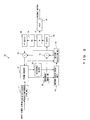
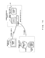
- Figs. 2 and 3 show the configurations of the conventional encoding/decoding devices, respectively.
- the encoding device 1a shown in Fig. 2 comprises a chrominance reduction/conversion unit 11, frame memory 12, a motion vector probe unit 13, a motion prediction unit 14, an orthogonal transform (T(DCT)) unit 15, a quantization (Q) unit 16, a variable length encoding (VLC) unit 17, an inverse quantization (IQ) unit 18, inverse orthogonal transform (IDCT) unit 19, an adder 20 and a subtractor 21.
- T(DCT) orthogonal transform
- Q quantization
- VLC variable length encoding
- IQ inverse quantization
- IDCT inverse orthogonal transform
- the chrominance reduction/conversion unit 11 reduces the chrominance of an inputted video signal, for example, from a 4:2:2 format signal to a 4:2:0 format signal.
- the frame memory 12 mainly stores frame data in order to predict a motion and stores image data in the past and the future.
- the motion vector probe unit 13 reads an original image macroblock 22 and a reference block 23 from the frame memory 12 and calculates a motion vector being the amount of movement of the reference block 23 from the original image macroblock 22 on the basis of them.
- the minimum predicted residual signal is selected on the basis of a certain criterion (absolute value sum or square-sum).
- the motion prediction unit 14 performs forward prediction, backward prediction and both-direction prediction on the basis of the reference frame in the frame memory 12 and the motion vector calculated by the motion vector probe unit 13 and generates a prediction frame.
- the subtractor 15 subtracts the prediction frame calculated by the motion prediction unit 14 from the original image macroblock 22 and outputs the difference to the orthogonal transform unit 16.
- the orthogonal transform unit 16 applies a direct cosign transform (DCT) to a pixel whose motion is compensated for every 8 ⁇ 8 blocks.
- the quantization unit 17 quantizes a DCT transform co-efficient taking a visual characteristic into consideration.
- the variable length encoding unit 18 converts the quantization value to a variable length code, such as a Huffman code or the like, and outputs the code.
- the inverse quantization unit 19 reversely converts the quantization value to the DCT transform co-efficient.
- the inverse orthogonal transform unit 20 reversely converts the DCT transform co-efficient calculated by the inverse quantization unit 18 to 8x8 blocks of pixel data.
- the adder 21 adds the prediction frame compensated for by the motion vector outputted from the motion prediction unit 14 to the pixel data of the differential value outputted from inverse orthogonal transform unit 20 and writes the pixel data to which distortion is added by compression into the memory frame 12 as a new reference frame.
- the encoding device 1a when a video signal 11 is inputted, format conversion for reducing the chrominance of the video signal is applied to the video signal by the chrominance reduction/conversion unit and then is stored in the frame memory 12. Then, an image data compression process, such as MPEG or the like, is applied to the video signal and its code is outputted.
- format conversion for reducing the chrominance of the video signal is applied to the video signal by the chrominance reduction/conversion unit and then is stored in the frame memory 12.
- an image data compression process such as MPEG or the like
- the video encoding device 1a the enormous amount of information of an original signal is compressed by eliminating the redundancy in the time and spatial direction. More specifically, for the time direction, a motion compensation method for eliminating a difference with previous and subsequent frames using a motion vector is used and for the spatial direction, orthogonal transform for transforming the horizontal/vertical planes of a screen to frequency components, the representative value of orthogonal transform co-efficient obtained by quantization or the like is used. Data compression is also performed using a variable length encoding as an arithmetic information compression method.
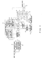
- Fig. 3 shows a configuration example of the conventional decoding device 2a.
- the decoding device 2a shown in Fig. 3 comprises a variable decoding (VLD) unit 31, an inverse quantization (IQ) unit 32, an inverse orthogonal transform (IDCT) unit 33, a motion compensation unit 34, an adder 35, frame memory 36 and a chrominance extension/conversion unit 37.
- VLD variable decoding
- IQ inverse quantization
- IDCT inverse orthogonal transform
- the variable decoding unit 31 converts the variable length code, such as a Huffman code or the like, to a quantum value.
- the inverse quantization unit 32 reversely converts a quantization value to a DCT transform co-efficient.
- the inverse orthogonal transform unit 33 reversely converts the DCT transform co-efficient calculated by the inverse quantization unit 32 to 8 ⁇ 8 blocks of pixel data.
- the pixel data calculated here is actual pixel data itself, in the case of a P or B picture, it is a differential value between two pieces of pixel data.
- the motion compensation unit 34 calculates a block compensated for by a motion vector used in the encoding device 1a.
- the adder 35 adds a differential value outputted from the inverse quantization unit 32 and the block compensated for by the motion vector outputted from the motion compensation unit 34 to calculate a P or B picture.
- the frame memory 36 stores the pixel data of the calculated frame.
- the chrominance extension/conversion unit 37 converts, for example, a 4:2:0 format signal whose chrominance is reduced by the encoding device 1a to a 4:2:2: format signal by compensating for the chrominance as a post-treatment.
- the decoding device 2a since the reverse of the encoding process of the encoding device 1a is performed, many of its components are the same as those included in the encoding device 1a.
- a differential value is calculated by the reverse of the encoding process of the encoding device 1a and in the motion compensation unit 34 it is decoded using a motion vector determined by the encoding device 1a.
- the chrominance extension/conversion unit 37 an extension process is applied to the code to which the chrominance reduction/conversion is applied at the pre-stage of the encoding process to transmit it as a video signal.
- a luminace is not always recognized more easily and depending on a scene, a chrominance sometimes is more characteristic than the luminance.
- This encoding device presumes compressing and encoding input video signals and in order to solve the above-described problem, it comprises a luminance complexity calculation unit, a chrominance complexity calculation unit, a reduction/conversion unit and an encoding unit.
- the luminance complexity calculation unit calculates the complexity of a luminance in the input video signal.
- the chrominance complexity calculation unit calculates the complexity of a chrominance in the input video signal.
- the reduction/conversion unit converts the format of the input video signal on the basis of the complexity of the luminance and chrominance calculated by the luminance complexity calculation unit and the chrominance complexity calculation unit, respectively.
- the encoding unit compresses/encodes the video signal to which format conversion is applied by the reduction/conversion unit to generate encoded data.
- This decoding device presumes decoding input encoded signals and comprises an image conversion specification unit, a decoding unit and an extension/conversion unit.
- the image conversion specification unit calculates the type of format conversion performed when the video signal is encoded.
- the decoding unit decodes the encoded signal on the basis of the type of format conversion from the image conversion specification unit.
- the extension/conversion unit converts the format of the signal decoded by the decoding unit on the basis of the type of format conversion from the image conversion specification unit.
- the present invention also includes the encoding method, decoding method and storage medium thereof in its scope.
- the encoding device in this preferred embodiment improves its coding process performance by adaptively modifying to which resolution conversion is applied, a luminance or a chrominance, on the basis of the complexity of an input video signal.
- the decoding device in this preferred embodiment determines to which resolution conversion is applied, a luminance or a chrominance on the basis of information attached to an encoded signal or the like and decodes the encoded data.
- a function to reduce/convert a luminance instead of a chrominance at the pre-stage of the decoding device and to maintain the resolution of a chrominance is added.
- a function to analyze the complexity of each of luminance/chrominance components of an input signal to encode and a function to determine which is reduced, a luminance component or a chrominance component on the basis of statistical information from the analysis unit is added.
- a function to determine which signal component is reduced, a chrominance component or a luminance component and to extend one of chrominance /luminance signals as the decoding process or the post -treatment of the decoding process is added.
- Information about which signal component is reduced, a chrominance or a luminance signal can be multiplexed in the bit stream of a signal to encode. Alternatively, the information can be tacitly determined by performing the same process in the encoding/decoding devices.
- a chrominance signal can be reduced as ever and if a pro-chrominance encoding is desired, a luminance can be reduced instead of a chrominance.
- Fig. 4 shows a configuration example of the encoding device 1b in this preferred embodiment.
- Fig. 1b the same reference numerals are attached to the same components as those of the encoding 1a shown in Fig. 2 .
- a luminance complexity calculation unit 41, a chrominance complexity calculation unit 42 and an encoding control unit 43 are newly provided and a reduction/conversion unit 44 is provided instead of the chrominance reduction/conversion unit 44.
- the luminance complexity calculation unit 41 calculates the complexity of a luminance in an input video signal.
- the chrominance complexity calculation unit 42 calculates the complexity of a chrominance in an input video signal.
- the luminance complexity calculation unit 41 calculates the distribution value ⁇ Y of a luminance, using Equation (1) and inputs it to the encoding control unit 43.
- the chrominance complexity calculation unit 42 calculates the distribution values ⁇ Cb and ⁇ Cr of a chrominance, using Equation (1) and inputs them to the encoding control unit 43.
- the encoding control unit 43 comprises a reduction determination unit 45, a picture format determination unit 46, an image reading unit 47, a prediction type determination unit 48 and a quantization determination unit 49.
- the reduction determination unit 45 determines which is larger in an input video signal, the complexity of a luminance or the complexity of a chrominance, on the basis of the distribution values ⁇ Y inputted from the luminance complexity calculation unit 41, ⁇ Cb and ⁇ Cr inputted from the chrominance complexity calculation unit 42.
- an offset ⁇ is added to the chrominance distribution value and ⁇ Y is compared with ⁇ Cb+ ⁇ Cr+ ⁇ .
- the picture format determination unit 4 6 determines which of a video signal is reduced, a luminance or a chrominance, on the basis of the determination result of the reduction determination unit 45 and instructs the reduction conversion unit 44 to do so.
- the image reading unit 47 controls blocks read from the frame memory 12.
- the prediction type determination unit 48 controls an arithmetic calculators 15 and 25 on the basis of how to predict, such as performing in-frame prediction or inter-frame prediction, performing frame prediction even in inter-frame prediction or field prediction, and the like.
- the quantization determination unit 49 controls the quantization unit 17 about the roughness of quantization on the basis of a compression ratio.
- the reduction conversion unit 44 converts an input video signal to a format signal in which a chrominance is reduced or to a format signal in which a luminance is reduced, according to the control instruction of the picture format determination unit 46.
- the complexity of each of the luminance and chrominance components of the input video signal is calculated. If the complexity of the luminance is small, the luminance is reduced. If the complexity of the chrominance is small, the chrominance is reduced. Then, after this format conversion of the video signal is performed, the video signal is compressed and reduced.
- Fig. 5 is a flowchart showing the operating process of the conventional encoding device 1a at the time of encoding an input video signal.
- step S0 the encoding device 1a reduces the chrominance component of a video signal by the chrominance reduction/ conversion unit 11. Then, in step S1 the format signal in which a chrominance is reduced is converted, for example, to a 4:2:0 format signal and is stored in the frame memory 12.
- step S2 0 is set in an MB counter value j (step S2). After that, the video signal in the memory frame 12 is encoded for each MB.
- step S3 an original image MB 22 and its reference block 23 are read and in step S3 a motion vector is probed for each MB by the motion vector probe unit12. Then, in step S4, motion prediction is conducted by the motion prediction unit 14 using the motion vector probed in step S3.
- step S5 0 is set in the counter value i of the block.
- step S6 the block is processed using the result of the motion prediction in step S5.
- This block process includes orthogonal transform, quantization, variable length encoding, inverse quantization and inverse orthogonal transform.
- This block process also includes MB type determination by which it is determined in what mode an MB is encoded, and the like.
- one MB is composed of six blocks of Y0, Y1, Y2, Y3, Cb and Cr.
- step S7 the block process is applied to all of these six blocks while incrementing the block counter value I (Yes in step S8).
- the counter value j of the MB is incremented. If the counter value j has not reached the total number of the MB yet (Yes in step S10), the above-described processes in steps S4 through S10 are repeatedly applied. If the counter value j has reach the total number of the MB (No in step S10) and the process of all the MB is completed, the process is terminated.
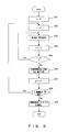
- Fig. 6 is a flowchart showing the operation of the encoding device in this preferred embodiment at the time of encoding an input video signal.
- the process shown in Fig. 6 comprises a process for determining the information of which is reduced/converted, a luminance or a chrominance when compared with that shown in Fig. 5 .
- step S11 distribution values ⁇ Y, and ⁇ Cb and ⁇ Cr indicating the complexity of the luminance and chrominance components, respectively, of an input video signal are calculated using Equation (1).
- step S12 the distribution value ⁇ Y of the luminance and the distribution values ⁇ Cb and ⁇ Cr of the chrominance that are calculated in step S11 are compared by the reduction determination unit 45 of the encoding control unit 43 and it is determined, the reduction of which is less influential, a luminance or a chrominance, specifically which is smaller, the distribution value ⁇ Y of the luminance or the distribution values ⁇ Cb and ⁇ Cr of the chrominance.
- the picture format determination unit 46 reduces the chrominance of the video signal and generates a 4:2:0 format signal (step S14).
- step S15 the picture format determination unit 46 reduces the luminance of the video signal and generates format signal in which the luminance has been reduced (step S16).
- this format signal in which the luminance is reduced is called a 2:2:2 format signal. This 2:2:2 format signal newly defined did not exist in the present video signal.
- Fig. 7 shows an example of the 2:2:2 format MB.
- the luminance has only two blocks Y0 and Y1 of and the number is half of the original 4:2:2 format signal.
- the chrominance has four blocks of Cb0, Cb1, Cr0 and Cr1 and the number is the same as the original 4:2:2 format signal.
- step S14 When a 4:2:0 format signal is generated in step S14, the processes in step S17 and after shown in Fig. 16 are the same as those in step S3 and after shown in Fig. 5 .
- step S16 Even when a 2:2:2 format signal is generated in step S16, the encoding process is performed for each MB.
- each MB of a 2:2:2 format signal is composed of six blocks of Y0, Y1, Cb0, Cb1, Cr0 and Cr1, and motion vector probe (step S18) and motion prediction by a motion vector obtained by the motion probe (step S19) are applied to these six blocks for each MB. Then, the block process (step S21) is applied to each block of the MB. These processes are almost the same as those in steps S2 through S10 shown in Fig. 5 .
- the complexity of the luminance and chrominance components of an input video signal can be calculated and information having less influence can be reduced.
- the encoding device in this preferred embodiment can concisely improve the encoding efficiency of a scene in which encoding degradation is conspicuous in the chrominance component by providing a mechanism for thinning out a luminance component instead of the chrominance component.
- the encoding device 1b in this preferred embodiment is not limited to only this.
- a Cr signal component red chrominance component
- encoding can be performed while maintaining the number of process blocks by modifying a reduction/extension ratio for each signal component, for example, reducing Y to 1/2 in each of the horizontal/vertical directions, reducing Cb to 1/2 in the vertical direction in such a way as to convert it to a 1:1:4 signal format and extending Cr to double or so on.
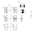
- Fig. 8 shows a configuration example of the decoding device 2b in this preferred embodiment.
- the same reference numerals are attached to the same components as in the conventional decoding device 2a of Fig. 3 .
- a reference frame conversion reading unit 51 and an image conversion specification unit 52 are newly provided and a conversion unit 53 is provided instead of the chrominance extension/conversion unit 37.
- the reference frame conversion reading unit 51 converts the format of the reference frame of the motion compensation unit 34 to the same format as the encoding format of a decoded picture on the basis of the notice on a signal format from the image conversion specification unit 52 and controls the motion compensation unit 34 to perform a motion compensation process.
- the image conversion specification unit 52 extracts choroma_format or mb_format described later that is multiplexed in an inputted bit stream, stores encoding format information for several minutes of picture to be stored in the frame memory 36 and notifies the reference frame conversion reading unit 51, the frame memory 36 and the extension conversion unit 37 of these from time to time.
- the motion compensation unit 34 decode it using the motion vectors (MV) multiplexed in the bit stream.
- the motion assurance unit 34 calculates a reference frame on the basis of formant specification from the image conversion specification unit 52.
- the conversion unit 53 performs an extension process to restore the format conversion performed at the pre-stage of the encoding process on the basis of format specification from the image conversion specification unit 52 and transmits it as a video signal.
- bit stream whose chrominance or luminance component is reduced/encoded by the encoding device 1b in this preferred embodiment can also be decoded by the decoding device 2b.
- Fig. 9 is a flowchart showing the operation process of the conventional decoding device 2a.
- step S31 0 is set in the counter value j of an MB to clear it.
- step S33 the counter value i of a block is incremented and a block process is applied to a block corresponding to the counter value i.
- a bit stream being a variable length code is converted to a quantization value, and conversion, inverse quantization and inverse transform processes are applied to it.
- the process in step S33 is applied to data for one MB (Yes in step S35) while incrementing the counter value i of the block (step S34).
- step S35 the motion compensation unit 34 performs motion compensation for each MB (step S36).
- step S39 the chrominance component is extended and a 4:2:2 format signal is generated. Then, the process is terminated.
- the generated 4:2:0 format video signal is converted to a 4:2:2 format signal.
- Fig. 10 is a flowchart showing the operation process of the decoding device 2b in this preferred embodiment.
- the decoding device 2b differs from the conventional device in that a signal component to be extended in the post-treatment of decoding adaptively differs.
- steps S41 through S48 shown in Fig. 10 until motion compensation is performed for each MB after a block process is performed for each block in step S43 is basically the same as the processes in steps S1 through S8 of the conventional decoding device 2a shown in Fig. 9 except for that since a reference frame varies depending on a signal format, the reference frame must be reported to the motion compensation unit 34.
- the extension conversion unit 53 recognizes the format of a signal decoded in up to step S48 on the basis of chroma_format or mb_format multiplexed in the bit stream and determines by reducing which the format has been obtained, a chrominance signal component or a luminance component.
- step S49 If in step S49 it is determined that a chrominance component has been reduced (chrominance in step S50), in step S50 the chrominance component is extended and a 4:2:2 format signal is generated/outputted. Then, the process is terminated. If in step S49 it is determined that a luminance component has been reduced (luminance in step S50), in step S51 the luminance component is extended and a 4:2:2 format signal is generated/outputted. Then, the process is terminated.
- extension /conversion unit 53 can also be determined which the extension /conversion unit 53 extends, a chrominance component or a luminance component by superimposing/transmitting information indicating the type of format (chroma_format or mb_format) on encoding information as one component of a picture header as in the above example.
- information in the decoding device 2b in advance as the statistical information and performing the same calculation on both the encoding and decoding sides, it can be tacitly determined which the extension/conversion unit 53 extends, a chrominance component or a luminance component, without attaching the information.
- I picture Intra-picture
- P picture predictive picture
- B picture bi-directionally predictive picture
- I picture is a reference picture, to which only spatial compression is applied and time compression is not applied, and its compression ratio is low.
- P picture besides spatial compression, time compression which takes in prediction only in the time axis forward direction and is based on a difference with the I picture is also applied.
- B picture besides spatial compression, bi-directional predicative compression using differences with previous and subsequent frames is applied. Therefore, the compression ratio of B picture is higher than that of P picture.
- GOP group of pictures
- encoding is performed for each GOP and the switch of a signal format at the pre-stage of encoding is also performed for each GOP.
- Fig. 11 shows the structure of the group of pictures.
- Fig. 11 shows an example of GOP in which two pieces of B picture continue after one piece of I or P picture to refer.
- motion prediction and compensation can be performed by the same resolution and their configurations become easy.
- B0 and B1 pictures refer to an I2 picture
- B3 and B4 pictures refer to I2 and P5 pictures
- a P5 picture refers to I2 picture
- B6 and B7 pictures refer to P5 and P8 pictures
- a P8 picture refer to a P5 picture
- B9 and B10 pictures refer to P8 and P11 pictures
- a P11 picture refers to a P8 picture
- B12 and B13 pictures refer to P11 and P14 pictures
- a P14 picture refers to a P11 picture.
- a picture to be referenced must be processed in advance, in Fig. 11 a picture is processed in the order of I2, B0, B1, P5, B3, B4, P8, B6, B7, P11, B9, B10, P14, B12 and B13.
- a signal format can be switched for each picture instead of for each GOP.
- the target picture whose luminance component is reduced is only B picture being non-reference picture.
- I and P pictures are converted to 4:2:0 format signals.
- B picture that is not referenced for motion prediction spreads no encoding noise in the time direction even when its accuracy is reduced
- accuracy-deteriorated encoding can be applied to B picture, for example, by a method of replacing it with the simple conversion of a motion vector or the like.
- a forward reference image and a backward reference image differs, for example, by modifying the resolution of the entire picture to the resolution of the current picture to encode, reading it and encoding it by the resolution, encoding can be performed at less accuracy loss.
- Fig. 12 shows an example of Sequence_extension information attached to each GOP of the bit stream encoded by the encoding device in this preferred embodiment.
- the Sequence_extension information includes chroma_format information 61 and this chroma_format information 61 stores information indicating the format of a picture in the corresponding GOP.
- Fig. 13 shows an example structure of choroma_extension information 61.
- Fig. 13A shows the structure in which the choroma_extension information 61 is made two bits and which shows that if the choroma_extension information 61 is "00", the format of the picture of the corresponding GOP is 2:2:2 and if it is "01", the format of the picture of the corresponding GOP is 4:2:0.
- Fig. 13B shows the structure in which the choroma_extension information 61 is made two bits in order to prevent it from being recognized to be START CODE when "0" continues.
- Fig. 13B shows that when the choroma_extension information 61 is "100", the format of the picture of the corresponding GOP is 2:2:2 and when it is "001", the format of the picture of its corresponding GOP is 4:2:0.
- the format of the encoded bit stream can be known by referring to this chroma_format information 61.
- Fig. 14A shows an example of Picture coding_extension information attached to each piece of the bit stream encoded by the encoding device in this preferred embodiment.
- mb_format information 71 is newly attached to the Picture coding_extension information and this mb_format information 71 includes information indicating the format of its corresponding picture.
- Fig. 14B shows an example of the.mb_format information 71.
- the mb_format information 71 is one bit and Fig. 14B shows that if this bit is "1", the format of its corresponding picture is converted to 2:2:2. If this bit is "0", the format of its corresponding picture is determined on the basis of the chroma_format information 61 in the Sequencw_extension information shown in Fig. 13 .
- the format of the encoded bit stream can be known by referring to this mb_format information 71.
- the encoding device 1b and decoding device 2b in this preferred embodiment is configured not only by the hardware shown in Figs. 4 and 8 , it can be also realized by software by executing a program in an information processing device.
- Fig. 15 shows the system environment of an information processing device by which the encoding device 1b and decoding device 2b in this preferred embodiment are realized.
- the information processing device shown in Fig. 15 comprises a CPU 81, a main storage device 82, such as RAM or the like, an auxiliary storage device 83, such as a hard disk or the like, an input/output device (I/O) 84, such as a display, a keyboard, a pointing device and the like, a network connecting device 85, such as a communication interface, a modem or the like, and a medium reading device for reading stored contents from a portable storage medium, such as a disk, a magnetic tape or the like, which are connected to each other by a bus 88.
- the components exchange data with each other via the bus 88.
- the CPU 81 realizes the function of each component of the encoding device 1b and decoding device 2b shown in Figs. 4 and 9 and the processes of the flowcharts shown in Figs. 6 and 10 by executing a program in the auxiliary storage device 83 and a program installed via the network connecting device 85 using the main storage device as working memory.
- the medium reading device 86 reads a program and data stored in a storage medium 87, such as a magnetic tape, a flexible disk, CR-ROM, an MO, a DVD or the like, and loads them onto the information processing device in this preferred embodiment via an external interface. Then, the program and data are stored in the main storage device 82 and the auxiliary storage device 83 and by executing the program using the data by the CPU 81, the processes of the above-described flowcharts are realized by software.
- a storage medium 87 such as a magnetic tape, a flexible disk, CR-ROM, an MO, a DVD or the like
- the present invention is not limited to an encoding device, a decoding device, an encoding method, a decoding method and a program and when being used by a computer, it can be also constituted as a computer-readable storage medium 87 or program for enabling the computer to implement the above-described function in this preferred embodiment of the present invention.
- the "storage medium” includes a portable storage medium 96 detachable/attachable from/to a medium driving device 97, such as CD-ROM, a flexible disk (or an MO, a DVD, a memory card, a removable disk, etc.), a storage unit (a database, etc.) 92 in an external device (a server, etc.) connected via a network line 93 and memory (RAM, a hard disk, etc.) 95 in the main body 94 of an information processing device 91 and the like.
- the program stored in the portable storage medium 96 and the storage unit (a database, etc.) 92 is loaded onto the memory (RAM, a hard disk, etc.) 95 and is executed.
- a next-generation optical disk storage medium using blue laser such as a Blu-ray Disc (trademark), An AOD (advanced optical disc) or the like, an HD-DVD9 using red laser, a blue-laser DVD using blue/purple laser, a hologram and the like are used.
- the present invention can be also implemented using such various large-capacity storage medium developed in the future.
- the encoding device in this preferred embodiment since when converting a format by thinning out the luminance or chrominance component of an input video signal and converting its resolution, the complexity of the luminance and chrominance components and the format is converted on the basis of the complexity, the encoding efficient of a scene in which the encoding degradation of a chrominance component is conspicuous can be more concisely improved.
- the number of blocks of data encoded by the encoding device 1b in this preferred embodiment is the same in the case of a 4:2:0 format and in the case of a 2: 2: 2 format, and their amount of process is also the same.
- signals encoded by the encoding device 1b can be decoded.
Landscapes
- Engineering & Computer Science (AREA)
- Multimedia (AREA)
- Signal Processing (AREA)
- Compression Or Coding Systems Of Tv Signals (AREA)
- Color Television Systems (AREA)
Applications Claiming Priority (1)
| Application Number | Priority Date | Filing Date | Title |
|---|---|---|---|
| JP2008139739A JP5195032B2 (ja) | 2008-05-28 | 2008-05-28 | 符号化装置/復号化装置、符号化方法/復号化方法及びプログラム |
Publications (2)
| Publication Number | Publication Date |
|---|---|
| EP2129132A2 true EP2129132A2 (de) | 2009-12-02 |
| EP2129132A3 EP2129132A3 (de) | 2013-07-31 |
Family
ID=40943824
Family Applications (1)
| Application Number | Title | Priority Date | Filing Date |
|---|---|---|---|
| EP20090002951 Withdrawn EP2129132A3 (de) | 2008-05-28 | 2009-03-02 | Kodier-/Dekodiervorrichtung, Kodier-/Dekodierverfahren und Datenträger |
Country Status (5)
| Country | Link |
|---|---|
| US (1) | US8761246B2 (de) |
| EP (1) | EP2129132A3 (de) |
| JP (1) | JP5195032B2 (de) |
| KR (1) | KR101090586B1 (de) |
| CN (1) | CN101594536A (de) |
Families Citing this family (13)
| Publication number | Priority date | Publication date | Assignee | Title |
|---|---|---|---|---|
| JP5310620B2 (ja) * | 2010-03-19 | 2013-10-09 | 富士通株式会社 | 動画像符号化装置、動画像符号化方法及び動画像符号化用コンピュータプログラムならびに映像伝送装置 |
| WO2012070500A1 (ja) * | 2010-11-22 | 2012-05-31 | ソニー株式会社 | 符号化装置および符号化方法、並びに、復号装置および復号方法 |
| WO2012118359A2 (ko) | 2011-03-03 | 2012-09-07 | 한국전자통신연구원 | 색차 성분 양자화 매개 변수 결정 방법 및 이러한 방법을 사용하는 장치 |
| US9363509B2 (en) | 2011-03-03 | 2016-06-07 | Electronics And Telecommunications Research Institute | Method for determining color difference component quantization parameter and device using the method |
| GB2506345A (en) * | 2012-09-06 | 2014-04-02 | British Broadcasting Corp | Video encoding and decoding with chrominance sub-sampling |
| JP6282763B2 (ja) * | 2012-09-21 | 2018-02-21 | 株式会社東芝 | 復号装置、符号化装置、復号方法、及び符号化方法 |
| US9699469B2 (en) | 2014-02-21 | 2017-07-04 | Lattice Semiconductor Corporation | Adaptive processing of video streams with reduced color resolution |
| USRE48920E1 (en) | 2014-02-21 | 2022-02-01 | Lattice Semiconductor Corporation | Adaptive processing of video streams with reduced color resolution |
| JP6365253B2 (ja) | 2014-11-12 | 2018-08-01 | 富士通株式会社 | 映像データ処理装置、映像データ処理プログラムおよび映像データ処理方法 |
| JP2018533286A (ja) * | 2015-09-23 | 2018-11-08 | エルジー エレクトロニクス インコーポレイティド | 画像の符号化/復号化方法及びこれのために装置 |
| CN115914637A (zh) * | 2021-09-30 | 2023-04-04 | 西安诺瓦星云科技股份有限公司 | 图像格式转换方法、装置和视频处理设备 |
| WO2023127940A1 (ja) * | 2021-12-29 | 2023-07-06 | ソニーグループ株式会社 | 画像処理装置および画像処理方法 |
| GB2617319B (en) * | 2022-03-31 | 2025-05-07 | V Nova Int Ltd | Low complexity enhancement video coding with signal element modification |
Citations (3)
| Publication number | Priority date | Publication date | Assignee | Title |
|---|---|---|---|---|
| JPH10164581A (ja) | 1996-12-03 | 1998-06-19 | Sony Corp | 画像信号符号化方法及び装置、信号記録媒体 |
| JPH11196437A (ja) | 1998-01-05 | 1999-07-21 | Nec Corp | 画像に於ける動き検出方法及び動き検出装置 |
| JP2007053788A (ja) | 2006-10-02 | 2007-03-01 | Sony Corp | 映像データ圧縮装置およびその方法 |
Family Cites Families (18)
| Publication number | Priority date | Publication date | Assignee | Title |
|---|---|---|---|---|
| JP3188135B2 (ja) | 1995-05-19 | 2001-07-16 | 三洋電機株式会社 | 映像信号処理回路 |
| JPH0970044A (ja) * | 1995-08-31 | 1997-03-11 | Sony Corp | 画像信号処理装置および方法 |
| JPH10117354A (ja) * | 1996-10-11 | 1998-05-06 | Matsushita Electric Ind Co Ltd | 動画伝送システム |
| JP3448462B2 (ja) | 1997-06-25 | 2003-09-22 | 三洋電機株式会社 | 画像データ圧縮装置 |
| CN100474931C (zh) * | 1997-11-05 | 2009-04-01 | 索尼公司 | 数字信号转换方法和数字信号转换装置 |
| US6317141B1 (en) * | 1998-12-31 | 2001-11-13 | Flashpoint Technology, Inc. | Method and apparatus for editing heterogeneous media objects in a digital imaging device |
| KR100339401B1 (ko) | 2000-05-09 | 2002-06-01 | 구자홍 | 포맷 변환 장치 |
| JP3743389B2 (ja) * | 2001-05-14 | 2006-02-08 | 株式会社ニコン | 画像圧縮装置および画像圧縮プログラム |
| US7035459B2 (en) * | 2001-05-14 | 2006-04-25 | Nikon Corporation | Image compression apparatus and image compression program |
| US7649947B2 (en) | 2001-06-05 | 2010-01-19 | Qualcomm Incorporated | Selective chrominance decimation for digital images |
| US20030095603A1 (en) * | 2001-11-16 | 2003-05-22 | Koninklijke Philips Electronics N.V. | Reduced-complexity video decoding using larger pixel-grid motion compensation |
| US7379496B2 (en) | 2002-09-04 | 2008-05-27 | Microsoft Corporation | Multi-resolution video coding and decoding |
| JP4084991B2 (ja) * | 2002-11-29 | 2008-04-30 | 富士通株式会社 | 映像入力装置 |
| JP2005303710A (ja) * | 2004-04-13 | 2005-10-27 | Seiko Epson Corp | 動画像符号化方法、画像処理装置および画像処理プログラム |
| JP4385841B2 (ja) | 2004-04-22 | 2009-12-16 | ソニー株式会社 | 画像処理装置 |
| KR100747530B1 (ko) * | 2004-12-13 | 2007-08-08 | 엘지전자 주식회사 | Pvr 시스템 및 그 방송 재생 방법 |
| JP4073942B2 (ja) * | 2006-12-01 | 2008-04-09 | シャープ株式会社 | 画像圧縮装置および画像伸張装置、ならびに画像圧縮方法および画像伸張方法をコンピュータに実行させるためのプログラムをそれぞれ記録したコンピュータ読取可能な記録媒体 |
| JP4605183B2 (ja) * | 2007-04-27 | 2011-01-05 | ソニー株式会社 | 画像信号処理装置及び方法 |
-
2008
- 2008-05-28 JP JP2008139739A patent/JP5195032B2/ja not_active Expired - Fee Related
-
2009
- 2009-03-02 EP EP20090002951 patent/EP2129132A3/de not_active Withdrawn
- 2009-03-02 US US12/396,089 patent/US8761246B2/en not_active Expired - Fee Related
- 2009-03-23 KR KR1020090024565A patent/KR101090586B1/ko not_active Expired - Fee Related
- 2009-03-24 CN CNA2009101196422A patent/CN101594536A/zh active Pending
Patent Citations (3)
| Publication number | Priority date | Publication date | Assignee | Title |
|---|---|---|---|---|
| JPH10164581A (ja) | 1996-12-03 | 1998-06-19 | Sony Corp | 画像信号符号化方法及び装置、信号記録媒体 |
| JPH11196437A (ja) | 1998-01-05 | 1999-07-21 | Nec Corp | 画像に於ける動き検出方法及び動き検出装置 |
| JP2007053788A (ja) | 2006-10-02 | 2007-03-01 | Sony Corp | 映像データ圧縮装置およびその方法 |
Also Published As
| Publication number | Publication date |
|---|---|
| KR101090586B1 (ko) | 2011-12-08 |
| JP2009290463A (ja) | 2009-12-10 |
| CN101594536A (zh) | 2009-12-02 |
| US8761246B2 (en) | 2014-06-24 |
| US20090296809A1 (en) | 2009-12-03 |
| JP5195032B2 (ja) | 2013-05-08 |
| KR20090123772A (ko) | 2009-12-02 |
| EP2129132A3 (de) | 2013-07-31 |
Similar Documents
| Publication | Publication Date | Title |
|---|---|---|
| US8761246B2 (en) | Encoding/decoding device, encoding/decoding method and storage medium | |
| JP4815107B2 (ja) | カラー平面間予測を利用した無損失映像符号化/復号化方法及び装置 | |
| US8260069B2 (en) | Color image encoding and decoding method and apparatus using a correlation between chrominance components | |
| JP2011130410A (ja) | 符号化方法、復号化方法及び装置 | |
| KR19980071541A (ko) | 화상 처리 장치와 화상 처리방법 | |
| EP2077670A1 (de) | Transcoder, transcodierverfahren, decoder und decodierverfahren | |
| JP2003116104A (ja) | 情報処理装置及び情報処理方法 | |
| KR20050074286A (ko) | 화상 부호화 장치, 화상 부호화 방법 및 화상 부호화프로그램 | |
| CN106028031B (zh) | 视频编码装置和方法、视频解码装置和方法 | |
| US7346108B2 (en) | Encoded-data converting apparatus and method for the same | |
| CN1825976B (zh) | 译码数字影像序列的方法及装置 | |
| US20170105012A1 (en) | Method and Apparatus for Cross Color Space Mode Decision | |
| JP2003169332A (ja) | 画像符号化方法及び画像復号化方法 | |
| JPH10229563A (ja) | 動画像符号化方法、及び動画像符号化装置 | |
| JP4126044B2 (ja) | 動画像符号化装置及び方法 | |
| CN104769945A (zh) | 编码和解码图像的方法、编码和解码装置、以及与其对应的计算机程序 | |
| JP2002232881A (ja) | 動画像復号化方法及び装置 | |
| JP4857152B2 (ja) | 直交変換・量子化装置 | |
| JP2011004051A (ja) | 動画像符号化方法,動画像符号化装置および動画像符号化プログラム | |
| US20070297517A1 (en) | Entropy encoding and decoding apparatuses, and entropy encoding and decoding methods | |
| JP4390009B2 (ja) | 符号化装置及び方法、画像処理システム | |
| JP2000152248A (ja) | 映像信号合成装置、映像信号合成方法、及び映像信号合成プログラムを記録した記録媒体 | |
| JP2006165801A (ja) | 符号化モード判定装置及び方法 | |
| JPH11122580A (ja) | 画像信号の編集装置、符号化装置及び復号装置 | |
| JP2003174653A (ja) | 画像情報変換方法及び画像情報変換装置、並びに制御プログラム及び記録媒体 |
Legal Events
| Date | Code | Title | Description |
|---|---|---|---|
| PUAI | Public reference made under article 153(3) epc to a published international application that has entered the european phase |
Free format text: ORIGINAL CODE: 0009012 |
|
| AK | Designated contracting states |
Kind code of ref document: A2 Designated state(s): AT BE BG CH CY CZ DE DK EE ES FI FR GB GR HR HU IE IS IT LI LT LU LV MC MK MT NL NO PL PT RO SE SI SK TR |
|
| AX | Request for extension of the european patent |
Extension state: AL BA RS |
|
| PUAL | Search report despatched |
Free format text: ORIGINAL CODE: 0009013 |
|
| AK | Designated contracting states |
Kind code of ref document: A3 Designated state(s): AT BE BG CH CY CZ DE DK EE ES FI FR GB GR HR HU IE IS IT LI LT LU LV MC MK MT NL NO PL PT RO SE SI SK TR |
|
| AX | Request for extension of the european patent |
Extension state: AL BA RS |
|
| 17P | Request for examination filed |
Effective date: 20131218 |
|
| RBV | Designated contracting states (corrected) |
Designated state(s): AT BE BG CH CY CZ DE DK EE ES FI FR GB GR HR HU IE IS IT LI LT LU LV MC MK MT NL NO PL PT RO SE SI SK TR |
|
| AKX | Designation fees paid |
Designated state(s): DE FR GB |
|
| 17Q | First examination report despatched |
Effective date: 20140619 |
|
| STAA | Information on the status of an ep patent application or granted ep patent |
Free format text: STATUS: THE APPLICATION IS DEEMED TO BE WITHDRAWN |
|
| 18D | Application deemed to be withdrawn |
Effective date: 20141030 |