EP2129145A1 - Procédé de production d'un signal de commande sans fil, station de base sans fil et station mobile - Google Patents
Procédé de production d'un signal de commande sans fil, station de base sans fil et station mobile Download PDFInfo
- Publication number
- EP2129145A1 EP2129145A1 EP08711994A EP08711994A EP2129145A1 EP 2129145 A1 EP2129145 A1 EP 2129145A1 EP 08711994 A EP08711994 A EP 08711994A EP 08711994 A EP08711994 A EP 08711994A EP 2129145 A1 EP2129145 A1 EP 2129145A1
- Authority
- EP
- European Patent Office
- Prior art keywords
- control signal
- control
- random access
- buffer status
- information
- Prior art date
- Legal status (The legal status is an assumption and is not a legal conclusion. Google has not performed a legal analysis and makes no representation as to the accuracy of the status listed.)
- Withdrawn
Links
Images







Classifications
-
- H—ELECTRICITY
- H04—ELECTRIC COMMUNICATION TECHNIQUE
- H04W—WIRELESS COMMUNICATION NETWORKS
- H04W28/00—Network traffic management; Network resource management
- H04W28/02—Traffic management, e.g. flow control or congestion control
- H04W28/06—Optimizing the usage of the radio link, e.g. header compression, information sizing, discarding information
- H04W28/065—Optimizing the usage of the radio link, e.g. header compression, information sizing, discarding information using assembly or disassembly of packets
-
- H—ELECTRICITY
- H04—ELECTRIC COMMUNICATION TECHNIQUE
- H04W—WIRELESS COMMUNICATION NETWORKS
- H04W74/00—Wireless channel access
- H04W74/08—Non-scheduled access, e.g. ALOHA
-
- H—ELECTRICITY
- H04—ELECTRIC COMMUNICATION TECHNIQUE
- H04W—WIRELESS COMMUNICATION NETWORKS
- H04W88/00—Devices specially adapted for wireless communication networks, e.g. terminals, base stations or access point devices
- H04W88/02—Terminal devices
-
- H—ELECTRICITY
- H04—ELECTRIC COMMUNICATION TECHNIQUE
- H04W—WIRELESS COMMUNICATION NETWORKS
- H04W88/00—Devices specially adapted for wireless communication networks, e.g. terminals, base stations or access point devices
- H04W88/08—Access point devices
-
- H—ELECTRICITY
- H04—ELECTRIC COMMUNICATION TECHNIQUE
- H04W—WIRELESS COMMUNICATION NETWORKS
- H04W72/00—Local resource management
- H04W72/20—Control channels or signalling for resource management
- H04W72/23—Control channels or signalling for resource management in the downlink direction of a wireless link, i.e. towards a terminal
Definitions
- the present invention generally relates to radio communications control techniques, and specifically relates to a configuration of a control signal for implementing a control process at the MAC (Medium Access Control) layer, and a process of generating such a control signal.
- MAC Medium Access Control
- SI Scheduling Information
- the above-described scheduling information SI is multiplexed in a MAC-e PDU and transmitted.
- the above-described four information elements are reported at a fixed number of bits of 18 (see Non-patent document 1).
- a method is considered that includes, in a header of the MAC control PDU, information on the message length and the number multiplexed for each of multiple types of control messages.
- this method a problem arises that overhead included in a MAC header increases in order to report the control messages multiplexed.
- a problem to be solved in the present invention is to provide a novel technique for creating a control signal configured to reduce header overhead to a minimum even when an unspecified number of and/or differently-sized control messages are multiplexed.
- Another problem to be solved is to provide a radio base station apparatus and a mobile station that are configured to be suitable for transmission and reception of the control signal as described above.
- the method of generating the control signal includes the steps of:
- a control signal may be generated that has added, to the control message block, a header including information indicating what the control signal is related to.
- information on what the control signal is related to may be transmitted in an auxiliary physical control channel transmitted as an accompaniment to the transport channel.
- control message is a set of random access responses which are generated in response to random access from one or more mobile stations, the random access response including a preamble sequence used by the respective mobile station and necessary information in response to it.
- the preamble sequence makes it possible to identify the mobile station which has made the random access and the size of the necessary information.
- control message is a buffer status report corresponding to each of one or more logical channel groups currently used by the mobile station.
- the buffer status report may be configured as fixed-length information or variable-length information.
- the former case makes it possible to identify the number of the multiplexed buffer status reports based on the fixed length and the size of the control signal.
- the control message includes a logical channel group ID and a buffer status report field corresponding to it, collating in advance the length of the buffer status report field corresponding to the logical channel group ID.
- the radio base station apparatus includes:
- a mobile station which is operable to respond to the base station as described above.
- the mobile station includes:
- a mobile station that generates a variable-length control signal transmitted in a transport channel.
- the mobile station includes
- a radio base station apparatus which is operable to respond to the base station as described above.
- the radio base station apparatus includes:
- control signal in which one or more control messages are multiplexed, of which control messages the number multiplexed and/or the message sizes are indefinite, while reducing the header overhead of the control signal to a minimum.
- the MAC control PDU which is an example of a control signal processed completely within a MAC layer, is transmitted to one or more UEs in a downlink shared channel (DL-SCH), which is a transport channel.
- DL-SCH downlink shared channel
- Each of the RA responses destined for one or more UEs that is multiplexed in a control signal is an example of a control message included in the control signal.
- the base station When multiple UEs access an eNB in a random access channel (RACH) in a radio subframe, the base station (eNB) includes different RA responses for the UEs to transmit the results.
- information on the number of multiplexed RA responses (control messages) and the length of the RA responses is not included in a MAC header, but is included in a message block of the MAC control PDU in a manner identifiable by the UE to transmit the results.
- FIG. 1A is a drawing illustrating an exemplary configuration of the MAC control PDU of the first embodiment of the invention.
- RA responses to UE1 and UE2 are multiplexed in a MAC control PDU 10 to transmit the multiplexed result in DL-SCH.
- an L1/L2 control channel which is a physical control channel, is generated and transmitted.
- the L1/L2 control channel transmits downlink resource block (RB) allocation information of a corresponding transport channel (DL-SCH in this example), transport format information, Hybrid ARQ information, and ID information such as cell-level user ID (C-RNTI) or cell-level UE group ID.
- RB downlink resource block
- C-RNTI cell-level user ID
- information transmitted in a corresponding transport channel may be a RA-RNTI, which shows that it is an RA response, in lieu of C-RNTI.
- Transport format information includes information on a block size (TB size) of a MAC control PDU 10 transmitted in the transport channel.
- TB size block size
- a MAC header size, a total of individual RA response sizes (control message block size), and the total of padding bit lengths are reported in order to determine, for how many UEs the RA responses are included in the MAC control PDU.
- the MAC control PDU 10 which makes up one TB, includes a MAC header 11, a control message block 12, and padding 13 for aligning the size of the MAC control PDU 10 per octet.
- the padding 13 is not needed if the size of the MAC control PDU 10 and/or the control message block 12 itself is octet-aligned (multiple of 8 bits).
- the MAC header 11, as shown in FIG. 2 includes at least a DDI (Data Description Indicator) field, an LI (Length Indicator) field, and an E (Extension) field.
- DDI is an indicator for identifying what the MAC control PDU 10 includes.
- FIG. 3 shows an exemplary DDI field.
- the MAC control PDU 10 is a signal conveying an RA response as a variable length control message, so that the first DDI in FIG. 2 has a value of "1100". Moreover, the MAC control PDU 10 includes a padding 13, so that the second DDI has "1011", indicating padding.
- LI designates the length of the RA response as a whole, or the length of the padding 13 in bits or octets. This value is variable.
- E field is a one bit field (flag) distinguishing whether a subsequent block is a control message block 12, or another set (LI+DDI+E), which is a part of a MAC header 11.
- the E flag behind the first DDI specifies a value (for example, "1") indicating that the following block is also a part of the MAC header 11.
- the E flag behind the second DDI specifies a value (for example, "0") indicating that the control message block 12 follows.
- the MAC header 11 only includes information indicating what the MAC control PDU is related to, and does not include information on the number and size of individual control messages included in the message block.
- a control message block 12 of a MAC control PDU 10 includes an RA response 12a destined for UE1 and an RA response 12b destined for UE2.
- the RA response 12a destined for UE1 and the RA response 12b destined for UE2 differ from each other in their message length. This is because the RACH transmit objective of UE1 and the RACH transmit objective of UE2 differ and constituting elements of the corresponding RA responses also differ.
- FIG. 4 is a diagram illustrating an exemplary configuration of an RA response according to a RACH transmit objective.
- RACH is a channel which is randomly transmitted from UE to eNB at the times of initial access of the UE, uplink synchronization establishment request, handover, and scheduling request.
- each UE generates and transmits a preamble sequence according to its RACH transmit objective.
- the base station eNB uses the received preamble sequence as UE identifying information, as the UE identifying information sets are not known at the time RACH is received.
- the RA response to the RACH for the initial access includes at least a preamble sequence, timing advance (T/A) information, UL grant information on resource allocation uplink, and C-RNTI (Cell Radio Network Temporary Identifier), which is an ID of a UE at the cell level managed by the network; the number of information bits (the message length) is X bits.
- T/A timing advance
- C-RNTI Cell Radio Network Temporary Identifier
- the RA response to the uplink synchronization establishment request includes at least preamble sequence and timing advance information, and the number of information bits is Y bits.
- the RA response to RACH with an objective of handover including at least a preamble sequence, timing advance information, and UL grant information, has a message length of Z bits.
- the RA response to the scheduling request also including at least a preamble sequence, timing advance information, and UL grant information, has a message length of W (may be the same as Z) bits.
- the RA response to UE1 is an RA response to an uplink synchronization establishment request, while the RA response to UE2 is an RA response of X bits to the initial access.
- MAC multiplexing is not applied to the RA response.
- the MAC control PDU does not include a control message block other than other user data and RA responses.
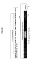
- FIG. 1B is a diagram illustrating a configuration of a MAC control PDU 10A as an exemplary variation of the configuration in FIG. 1A .
- the MAC header 11 is omitted.
- the L1/L2 control channel transmits RA-RNTI as ID information indicating that it is a RA response to one or more UEs, instead of UE identifying information (C-RNTI, etc.) for allocating a resource block to an individual UE.
- Each UE can recognize, by an L1/L2 control channel, that this MAC control PDU 10A relates to an RA response, so that the MAC header 11 may be omitted.
- RA-RNTI can also be transmitted in the L1/12 control channel while maintaining a MAC header 11A in FIG. 1A .
- a UE which has received a MAC control PDU 10 or MAC control PDU 10A first looks at an identifier (RA-RNTI) included in the MAC header 11 or L1/L2 control channel to recognize that the MAC control PDU is to report the RA response. Then, it can look at a preamble sequence included in a control message block 12 to identify a RACH transmit objective and determine the message length of the RA response identified with the preamble sequence. UE also can use the preamble sequence to determine whether an RA response which may be destined for the own station is included in the MAC control PDU 10.
- RA-RNTI an identifier included in the MAC header 11 or L1/L2 control channel
- each UE can scan preamble information of the control message block 12 to see these information sets without including, in the MAC header 11, information related to the size of multiplexed individual RA responses or the number of them multiplexed.
- the eNB When the eNB receives a RACH only from a single UE in a radio sub frame, only one RA response destined for one UE is included in the MAC control PDU 10. Even in such a case, control messages of different message lengths are included according to the RACH transmit objective. Thus, the length of the MAC control PDU 10 becomes variable. The UE can see the type and size of the control message (RA response) from the preamble sequence of the control message block 12.
- all of the RA responses may be configured with the four information elements rather than according to the RACH transmit objective.
- each RA response becomes fixed in length, but the MAC control PDU 10 becomes variable in length according to the number of UEs for which RA responses are multiplexed.
- Preamble sequences destined for multiple UEs may be arranged in ascending or descending order. In this case, when a value bigger than or smaller than the preamble sequence sent by the own station is detected, the UE can determine that the RA response which may be destined for the own station is not included and to stop further scanning.
- FIG. 5 (a) and 5 (b) are operational flows for the above-described base station (eNB) and mobile station (UE).
- the base station receives a RACH including a random access preamble sequence from one or more UEs located in an area in a radio sub frame (S101). Random access preamble sequences per UE are detected from the received RACH (S102), and RA responses corresponding to the transmit objectives are generated according to the preamble sequences detected (S103). The generated RA responses are multiplexed and padding is added, if necessary, to generate a MAC control PDU (S104).
- information for inserting into a MAC header it is sufficient to only include information identifying that the MAC control PDU is a control signal for transmitting a RA response, and information indicating the presence of any padding, so that information on the number of RA responses multiplexed and information on the message length of each RA response are not included.
- a base station generates and transmits an L1/L2 control channel (S105).
- L1/L2 control channel TB size information on the MAC control PDU, and downlink RB allocation information indicating a resource block allocated to a transport channel for transmitting the MAC control PDU are included.
- RA-RNTI which is an identifier for identifying that it is a RA response to a UE which has transmitted a RA preamble, may be included in lieu of C-RNTI, which is information identifying a UE that is used for a normal data allocation for allocating a resource block to an individual UE.
- C-RNTI which is information identifying a UE that is used for a normal data allocation for allocating a resource block to an individual UE.
- the generated MAC control PDU is transmitted in DL-SCH, for example (S106).
- the preamble sequence is generated and transmitted according to its objective (S201).
- the L1/L2 control channel is received from a base station (S202), and RB information allocated to a corresponding transport channel is extracted to receive DL-SCH (S203).
- TB size information is also extracted from the L1/L2 control channel.
- the MAC control PDU is extracted from the DL-SCH (S204), and the extracted MAC control PDU is analyzed (S205) .
- An example of analyzing the MAC control PDU is as explained with reference to FIG. 1A .
- eNB can, while reducing the overhead of the MAC header to a minimum, transmit a control signal (MAC control PDU) in which control messages destined for multiple UEs are multiplexed, allowing each UE to performs within a MAC layer completely the processes of detecting and analyzing the control messages included in the control signal.
- MAC control PDU control signal
- FIG. 6 is a block diagram of a base station (eNB) 30 and a mobile station (UE) 50 of the first embodiment.
- the base station 30 has a MAC PDU generator 31, an L1/L2 control channel generator 34, a transmitter 35, a receiver 36, and a RA (random access) preamble extracting unit 37.
- the MAC PDU generator 31 includes a RA (random access) response generator 32 and a MAC control PDU generator 33.
- a random access preamble of each UE is extracted at the RA preamble extracting unit 37.
- the RA response generator 32 generates an RA response the content of which is according to the corresponding preamble as shown in FIG. 4 .
- the MAC control PDU generator 33 multiplexes the generated RA responses, and adds a MAC header indicating that it is the RA response to generate a MAC control PDU as shown in FIG. 1A .
- the L1/L2 control channel generator 34 the L1/L2 control channel, which is an accompanying physical control channel, is generated and the TB size of the MAC control PDU and downlink RB information are inserted.
- the L1/L2 control channel generator 34 includes, in the L1/L2 channel, an RA-RNTI, which indicates that what is transmitted in a corresponding transport channel (DL-SCH) is an RA response.
- the MAC control PDU is transmitted from the transmitter 35, together with the L1/L2 control channel.
- the mobile station (UE) 50 has a MAC PDU processor 51, an L1/L2 control channel processor 54, a transmitter 55, a receiver 56, a random access (RA) preamble generator 57, and a C-RNTI storage 58.
- the MAC PDU processor 51 has an RA response processor 52 and a MAC control PDU determining unit 53.
- the RA preamble processor 57 When the UE 50 randomly accesses the eNB 30, the RA preamble processor 57 generates a preamble sequence according to the random access objective, and transmits a RACH from the transmitter 53.
- the L1/L2 control channel and DL-SCH, the corresponding transport channel are received.
- the L1/L2 control channel processor 54 takes out TB block size information transmitted in the L1/L2 control channel and provides the taken out information to the MAC PDU processor 51.
- the MAC control PDU transmitted in DL-SCH is provided to the MAC control PDU determining unit 53, where whether the RA response is destined for the UE 50 is determined.
- the method determines whether a DDI field of the MAC header 11 indicates an RA response signal, and if so, looks at a preamble included in the message block 12 to determine whether there is an RA response which may be destined for the own station. Alternatively, whether the received MAC control PDU is an RA response is determined.
- TB size information extracted from the L1/L2 control channel leads to knowing the message block size, and knowing for how many UEs the included RA responses are for.
- the preamble sequence When the preamble sequence is arranged in an ascending or descending order, it is determined that, when a preamble sequence larger or smaller, respectively, than that sent by the own station is detected, an RA response which may be destined for the own station is not included, so that no further process is performed.
- a MAC control PDU is provided to the RA response processor 52.
- the RA response processor 52 analyzes and processes the RA response which may be destined for the own station.
- an included C-RNTI is extracted to store the extracted result in the C-RNTI storage 58, so that this ID is subsequently used for communicating with the eNB.
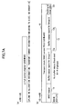
- FIG. 7A is a schematic drawing illustrating a configuration of the MAC control PDU of the second embodiment of the invention.
- an amount held in a buffer is transmitted from a mobile station (UE) to a base station (eNB) in one MAC control PDU as a buffer status report value (control message) for each of one or more logical channel groups (service groups) currently used by the UE.
- the base station uses it as scheduling information (SI) to perform uplink scheduling.
- SI scheduling information
- a buffer status report value corresponding to each of one or more groups is fixed in length, but the total size of the buffer status report message of the MAC control PDU varies according to the number N of logical channel groups (service groups) to be reported.
- the logical channel group may be divided into a group requiring a high-priority service quality, a group requiring a medium-level service quality, and a group requiring a low-priority service quality.
- the UE may simultaneously receive services of two types of quality or may only receive a service of a single service group, so that a MAC control PDU may vary in length accordingly.
- FIG. 7A (a) is an L1/L2 control channel transmitted by eNB at the time of scheduling.
- uplink resource unit (RU) allocation information for use in reporting scheduling information by UE transport format information including a TB size, a cell-level UE ID, or a cell-level UE group ID is transmitted.
- RU uplink resource unit
- FIG. 7A (b) is a block diagram of a MAC control PDU 10, which is generated when a UE sends, to the eNB, a buffer status report (scheduling information).
- the MAC control PDU 10 includes a MAC header 11, a control message block 12 and, as necessary, a block 23 for padding or for user data (DTCH/DCCH).
- the MAC header 11 includes DDI and E fields.
- DDI has a specific value indicating that a buffer status report (scheduling information) is included.
- a DDI showing the presence and an LI field showing the message length of the buffer status reporting part or the length of padding or user data 23 are also included.
- a buffer status report 12a of group I high-priority group
- a buffer status report 12b of group 3 low-priority group
- the number N of the groups reported is uniquely determined from the TB size and the size of the fixed-length buffer status report.
- FIG. 7B shows, as an exemplary variation of FIG. 7A , a configuration when each buffer status report (control message) included in the control message block 12 is variable in length.
- the group ID is fixed in length, but the length of the field indicating the report value varies from one group to another.
- the length (size) of the report value field is collated in advance with the group ID, and the eNB which receives the MAC control PDU 10 may know the size of the corresponding report value field by looking at the group ID. Thus, it is not necessary to include, in the MAC header 11, information on the size of each control message.
- the above described is an example such that data is currently transmitted and received between UE and eNB, with uplink synchronization being maintained between eNB and UE.
- data transmission and reception may be restarted with a request for establishing uplink synchronization from the UE when long-period intermittent transmitting and receiving are being conducted in an RRC_CONNECTED status, or when the uplink of the UE is out of synchronization due to individual uplink resources being released.
- a format different from normal buffer status reports of FIGS. 7A(b) and 7B(b) is used to transmit scheduling information.
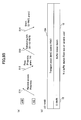
- FIG. 8A is an exemplary configuration of a MAC control PDU for reporting buffer status at the time of data restart.
- the UE first transmits a RACH preamble to the eNB for making a request for establishing uplink synchronization (S11).
- the eNB determines from the preamble sequence that this RACH is transmitted for the objective of establishing uplink synchronization (S12).
- the RA response as shown in FIG. 4 , for example, includes a preamble sequence transmitted by the UE, UL grant information and timing advance information.
- the UE upon receiving the RA response, uses an uplink RU allocated in the UL grant to transmit a MAC control PDU for reporting a buffer status report as scheduling information (S13).
- the MAC control PDU includes a C-RNTI, which is provided to the UE for identifying the UE, in addition to the buffer status report. Subsequently, the eNB uses this C-RNTI to report an allocation RU to the UE (S14). Please see 3GPP TSG RAN WG2 #57, R2-070781, 12 th -16 th February, 2007, St. Louis, USA for uplink synchronization in the RRC_CONNECTED status.
- FIG. 8A (b) is an example of a configuration of a MAC control PDU 10A transmitted from a UE at the time of data restart.
- a MAC control PDU 10A includes a MAC header 11, a C-RNTI 15, and a control message block 12. Each control message included in the control message block 12 may be fixed in length as in FIG. 7A or variable in length as in FIG. 7B .
- C-RNTI 15 is always arranged before the control message block 12. This is because the eNB may recognize the C-RNTI to obtain from the eNB itself or a network, services from the groups the UE is currently receiving (the value of N).
- the MAC header 11 includes a DDI indicating that a C-RNTI is included and a DDI indicating that a buffer status report is included. Alternatively, a single DDI may indicate that both C-RNTI and buffer status report are included.
- FIG. 8B is an exemplary variation of FIG. 8A .
- the MAC header 11 is omitted in the MAC control PDU 10A.
- uplink information to be sent next by the UE using a resource allocated in the response in S12 is determined in advance to be a buffer status report (and the C-RNTI, which is an identifier for the UE). This makes it possible for the eNB to know the value of the buffer status report value per group of services currently received by the UE identified by the C-RNTI.
- a buffer status report per logical channel group is included in the control message block 12.
- it may be configured such that, in addition to the buffer status report, an information element of a known size that is other than a buffer status report such as UPH is always included in the control message block 12.
- FIG. 9 is a flowchart indicating operational flows of UE and eNB of the second embodiment.
- the UE enters a scheduling information transmission process with a buffer status report trigger generated in the controller, for example (S301).
- a buffer status report trigger generated in the controller, for example (S301).
- S302 the uplink data restart
- S303 the uplink start is after establishing the uplink synchronization
- S303 the MAC control PDU
- the value of the buffer status report per logical channel group (service group) is multiplexed (S304).
- step S304 If the present buffer status report is not due to uplink data restart (NO in S302), the process goes to step S304, and the buffer status reports of the groups are multiplexed without multiplexing the C-RNTI. Then, the generated MAC control PDU is transmitted in UL-SCH (S305).
- FIG. 9(b) is an operation of the eNB of the second embodiment.
- the MAC control PDU is extracted (S402). It is determined whether the MAC control PDU is a buffer report due to restart of uplink data from the DDI of the MAC header 11 or RA preamble received in advance (S403). If it is a buffer report due to the uplink data restart (YES in S403), C-RNTI is extracted from the MAC control PDU and analyzed (S404). In this way, the presence of the UE on the network may be identified and how many logical channel groups are being used by the UE on the current network (services of how many service groups are being received) may be known. Moreover, the buffer status of each logical channel group is analyzed (S405), based on which information scheduling is conducted.
- FIG. 10 is a block diagram illustrating the eNB and the UE of the second embodiment;
- the UE 50 has a MAC PDU generator 61, a buffer status monitor 65, an uplink data retransmission determining unit 66, a C-RNTI storage 58, an L1/L2 control channel processor 54, a transmitter 56, and a receiver 56.
- the MAC PDU generator 61 includes a buffer status report generator 62 and a MAC control PDU generator 63.
- the UE 50 determines, at the uplink data restart determining unit 66, whether the present buffer status report is due to uplink data restart. If it is due to the uplink data restart, an RA preamble is transmitted prior to the buffer status report, and a request for uplink data restart is reported to the eNB, expecting a resource allocation for reporting the buffer status report.
- the MAC control PDU generator 63 when a resource for reporting buffer status is allocated to the UE, the MAC control PDU generator 63, according to the result of determining of the uplink restart determining unit 66, multiplexes C-RNTIs stored in the C-RNTI storage 58 in the MAC control PDU, or generates a MAC control PDU without multiplexing.
- the buffer status monitor 65 detects an amount held in the buffer per logical channel group, and provides the results to the MAC control PDU generator.
- the MAC control PDU generator 63 associates, with a group ID, an amount of each group that is held in a buffer to multiplex in the MAC control PDU.
- the L1/L2 control channel processor 54 takes out a TB size from an L1/L2 control channel received at the receiver 56 to provide to the MAC PDU generator 61.
- the eNB 30 has a MAC PDU processor 41, an L1/L2 control channel generator 34, a transmitter 35, a receiver 36, and a scheduler 45.
- the MAC PDU processor 41 includes a buffer status report processor 42 and a MAC control PDU determining unit 43.
- the MAC control PDU received at the receiver 36 is sent to the MAC control PDU determining unit 43.
- the MAC control PDU determining unit 43 looks at the MAC header to determine whether the MAC control PDU is a signal for reporting the buffer status, and whether the buffer status report includes the UE C-RNTI. Moreover, buffer status reports on how many groups are included may also be determined from the MAC control PDU TB size. Alternatively, when the MAC control PDU does not include a header, the MAC control PDU determining unit 43 may determine that the MAC control PDU is a buffer status report signal from an uplink resource block allocated according to a random access from a UE requesting uplink synchronization establishment, and a receive timing of the MAC control PDU.
- the buffer status report processor 42 takes out buffer status reports for each of the logical channel groups from the control message block of the MAC control PDU to analyze the reports taken out, and provides the results of the analysis to the scheduler 45. Moreover, when the MAC control PDU includes the C-RNTI, it is retrieved and stored in a C-RNTI storage. The scheduling section 45 performs scheduling for the UE 50 based on the analyzed buffer status reports (SI). Moreover, the L1/L2 control channel generated in the L1/L2 control channel generator 34 is transmitted from the transmitter 35.
- SI buffer status report signal
- the UE may generate and transmit a MAC control PDU of variable length according to N, the number of logical channel groups currently used.
- the eNB may look at a MAC header to determine whether the buffer status report is a normal scheduling status report signal, or scheduling information at the time of restarting data transmission after establishing uplink synchronization.
- variable-length MAC control PDU which varies in the size and number of control messages multiplexed according to circumstances while reducing the overhead of the MAC header to a minimum.
Landscapes
- Engineering & Computer Science (AREA)
- Computer Networks & Wireless Communication (AREA)
- Signal Processing (AREA)
- Mobile Radio Communication Systems (AREA)
- Data Exchanges In Wide-Area Networks (AREA)
Applications Claiming Priority (2)
| Application Number | Priority Date | Filing Date | Title |
|---|---|---|---|
| JP2007050834A JP4545768B2 (ja) | 2007-02-28 | 2007-02-28 | 無線制御信号生成方法、無線基地局装置、および移動局 |
| PCT/JP2008/053310 WO2008105412A1 (fr) | 2007-02-28 | 2008-02-26 | Procédé de production d'un signal de commande sans fil, station de base sans fil et station mobile |
Publications (2)
| Publication Number | Publication Date |
|---|---|
| EP2129145A1 true EP2129145A1 (fr) | 2009-12-02 |
| EP2129145A4 EP2129145A4 (fr) | 2011-05-18 |
Family
ID=39721243
Family Applications (1)
| Application Number | Title | Priority Date | Filing Date |
|---|---|---|---|
| EP08711994A Withdrawn EP2129145A4 (fr) | 2007-02-28 | 2008-02-26 | Procédé de production d'un signal de commande sans fil, station de base sans fil et station mobile |
Country Status (11)
| Country | Link |
|---|---|
| US (1) | US20100085926A1 (fr) |
| EP (1) | EP2129145A4 (fr) |
| JP (1) | JP4545768B2 (fr) |
| KR (1) | KR20090122225A (fr) |
| CN (1) | CN101647306A (fr) |
| AU (1) | AU2008220074A1 (fr) |
| BR (1) | BRPI0807577A2 (fr) |
| CA (1) | CA2678664C (fr) |
| MX (1) | MX2009008795A (fr) |
| RU (1) | RU2009134091A (fr) |
| WO (1) | WO2008105412A1 (fr) |
Families Citing this family (29)
| Publication number | Priority date | Publication date | Assignee | Title |
|---|---|---|---|---|
| TR201815388T4 (tr) | 2008-03-07 | 2018-11-21 | Nec Corp | Radyo haberleşme sistemi, haberleşme aygıtı, radyo haberleşme şebekesi sistemi ve buna ait yöntem. |
| US8483134B2 (en) | 2008-06-17 | 2013-07-09 | Panasonic Corporation | Radio transmission appratus and radio transmission method that switch between communication methods |
| US8228851B2 (en) * | 2008-11-03 | 2012-07-24 | Htc Corporation | Method for handling random access response reception and an E-UTRAN and user equipment thereof |
| KR101566555B1 (ko) | 2008-11-27 | 2015-11-05 | 삼성전자주식회사 | Mac헤더를 구성하는 방법 및 시스템 |
| CN102396192B (zh) | 2009-04-16 | 2018-02-16 | 皇家飞利浦电子股份有限公司 | 自适应缓冲器状态报告 |
| CN101873713A (zh) * | 2009-04-24 | 2010-10-27 | 中兴通讯股份有限公司 | 随机接入方法、终端 |
| US9258088B2 (en) | 2010-06-18 | 2016-02-09 | Acer Incorporated | Method of performing buffer status reporting and communication device thereof |
| EP3425954B1 (fr) * | 2010-06-18 | 2024-04-03 | LG Electronics Inc. | Procédé de transmission de rapport d'état de tampon de terminal a la station de base dans un système de communication sans fil et appareils associés |
| EP2398273B1 (fr) * | 2010-06-18 | 2018-02-14 | Acer Incorporated | Procédé de traitement de rapport d'état du tampon et dispositif de communication associé |
| WO2012124071A1 (fr) * | 2011-03-16 | 2012-09-20 | 富士通株式会社 | Station de base, dispositif d'authentification et terminal |
| CN102573011B (zh) * | 2012-02-17 | 2015-05-20 | 大唐移动通信设备有限公司 | 一种接入控制方法和设备 |
| US9544099B2 (en) * | 2012-07-02 | 2017-01-10 | Intel Corporation | User equipment, evolved node B, and method for multicast device-to-device communications |
| CN104541539B (zh) * | 2012-07-20 | 2018-05-15 | Lg 电子株式会社 | 无线通信系统中关于设备对设备连接的干扰的信息的方法和设备 |
| CN103634915A (zh) * | 2012-08-27 | 2014-03-12 | 中兴通讯股份有限公司 | 随机接入响应的方法及装置 |
| WO2014067052A1 (fr) * | 2012-10-29 | 2014-05-08 | Qualcomm Incorporated | Allocation de largeur de bande sélective à haute priorité pour les communications à accès multiples par répartition temporelle |
| US9973980B2 (en) * | 2013-03-06 | 2018-05-15 | Qualcomm Incorporated | Communications methods and apparatus that facilitate handover decisions and related measurements |
| CN104247541B (zh) * | 2013-03-12 | 2018-04-20 | 华为技术有限公司 | 传输数据处理方法及设备 |
| US9713032B2 (en) * | 2013-04-22 | 2017-07-18 | Telefonaktiebolaget Lm Ericsson (Publ) | Transmission of a random access response message |
| CN104952224A (zh) * | 2014-03-28 | 2015-09-30 | 海尔集团公司 | 用于网络配置信息传输的方法、终端和家电设备 |
| KR102189748B1 (ko) * | 2014-03-29 | 2020-12-14 | 주식회사 쏠리드 | 자동 아이디 할당이 가능한 일 대 다중 통신 시스템 |
| US20160373509A1 (en) * | 2015-06-16 | 2016-12-22 | Sk Telecom Co., Ltd. | APPARATUS AND METHOD FOR REPORTING QoS/QoE IN MOBILE ENVIRONMENT |
| KR102577085B1 (ko) | 2015-07-20 | 2023-09-11 | 삼성전자주식회사 | 무선 통신 시스템에서 통신 방법 및 장치 |
| JP6782467B2 (ja) * | 2015-11-04 | 2020-11-11 | パナソニックIpマネジメント株式会社 | 無線通信システムにおける制御信号の送信装置および送信方法 |
| DE112016007007T5 (de) | 2016-06-22 | 2019-03-07 | Intel Corporation | Kommunikationsvorrichtung und verfahren für vollduplex-disposition |
| US10952257B2 (en) | 2016-11-23 | 2021-03-16 | Electronics And Telecommunications Research Institute | Access method in communication system and device for performing same |
| CN108282901B (zh) * | 2017-01-06 | 2019-08-09 | 电信科学技术研究院 | 一种随机接入响应方法和装置 |
| BR112019026629A2 (pt) * | 2017-06-16 | 2020-06-30 | Telefonaktiebolaget Lm Ericsson (Publ) | método em um nó de rede operável em uma rede de comunicações sem fio, método em um dispositivo terminal, dispositivo terminal e nó de rede para uma rede de comunicações sem fio |
| CN119183209A (zh) | 2018-09-21 | 2024-12-24 | 三星电子株式会社 | 用于支持用于2步随机接入过程的方法和装置 |
| US11272532B2 (en) | 2018-11-01 | 2022-03-08 | Comcast Cable Communications, Llc | Random access response reception |
Family Cites Families (7)
| Publication number | Priority date | Publication date | Assignee | Title |
|---|---|---|---|---|
| ATE418190T1 (de) * | 2000-01-14 | 2009-01-15 | Interdigital Tech Corp | Drahtloses kommunikationssystem mit selektiv dimensionierten datentransportblöcken |
| JP4116925B2 (ja) * | 2003-05-13 | 2008-07-09 | 松下電器産業株式会社 | 無線基地局装置、制御局装置、通信端末装置、送信信号生成方法、受信方法及び無線通信システム |
| DE10345220B4 (de) * | 2003-09-29 | 2012-02-16 | Infineon Technologies Ag | Verfahren zur Übertragung von Daten |
| WO2006000094A1 (fr) * | 2004-06-24 | 2006-01-05 | Nortel Networks Limited | Mises a jour de position, appels de recherche et courtes rafales de donnees a efficacite elevee |
| JP4391562B2 (ja) * | 2005-03-04 | 2009-12-24 | 富士通株式会社 | 無線通信装置 |
| AU2006225460A1 (en) * | 2005-03-22 | 2006-09-28 | Samsung Electronics Co., Ltd. | Method and apparatus for transmitting packet data |
| JP2007050834A (ja) | 2005-08-19 | 2007-03-01 | Denso Corp | 車両用遮光装置 |
-
2007
- 2007-02-28 JP JP2007050834A patent/JP4545768B2/ja not_active Expired - Fee Related
-
2008
- 2008-02-26 CN CN200880010169A patent/CN101647306A/zh active Pending
- 2008-02-26 KR KR20097018623A patent/KR20090122225A/ko not_active Ceased
- 2008-02-26 US US12/528,242 patent/US20100085926A1/en not_active Abandoned
- 2008-02-26 EP EP08711994A patent/EP2129145A4/fr not_active Withdrawn
- 2008-02-26 MX MX2009008795A patent/MX2009008795A/es active IP Right Grant
- 2008-02-26 WO PCT/JP2008/053310 patent/WO2008105412A1/fr not_active Ceased
- 2008-02-26 RU RU2009134091/09A patent/RU2009134091A/ru not_active Application Discontinuation
- 2008-02-26 CA CA 2678664 patent/CA2678664C/fr not_active Expired - Fee Related
- 2008-02-26 BR BRPI0807577-8A2A patent/BRPI0807577A2/pt not_active IP Right Cessation
- 2008-02-26 AU AU2008220074A patent/AU2008220074A1/en not_active Abandoned
Non-Patent Citations (5)
| Title |
|---|
| "MAC PDU structure for LTE", 3GPP DRAFT; R2-070541, 3RD GENERATION PARTNERSHIP PROJECT (3GPP), MOBILE COMPETENCE CENTRE ; 650, ROUTE DES LUCIOLES ; F-06921 SOPHIA-ANTIPOLIS CEDEX ; FRANCE, [Online] no. R2-070782, 12 February 2007 (2007-02-12), pages 1-5, XP008125210, Retrieved from the Internet: URL:http://www.ftp.3gpp.org/tsg_ran/WG2_RL2/TSGR2_57/Documents/R2-070782.zip> * |
| "Uplink synchronization", 3GPP DRAFT; R2-070541, 3RD GENERATION PARTNERSHIP PROJECT (3GPP), MOBILE COMPETENCE CENTRE ; 650, ROUTE DES LUCIOLES ; F-06921 SOPHIA-ANTIPOLIS CEDEX ; FRANCE, [Online] no. R2-070781, 12 February 2007 (2007-02-12), pages 1-3, XP008125209, Retrieved from the Internet: URL:http://www.ftp.3gpp.org/ftp_ran/WG2_RL2/TSGR2_57/Documents/R2-070781.zip> * |
| LG ELECTRONICS INC: "Issue on message 2 transmission", 3GPP DRAFT; R2-070525_ISSUE ON MESSAGE2 TRANSMISSION_REV0.0, 3RD GENERATION PARTNERSHIP PROJECT (3GPP), MOBILE COMPETENCE CENTRE ; 650, ROUTE DES LUCIOLES ; F-06921 SOPHIA-ANTIPOLIS CEDEX ; FRANCE, vol. RAN WG2, no. St. Louis, USA; 20070209, 9 February 2007 (2007-02-09), XP050133579, [retrieved on 2007-02-09] * |
| NTT DOCOMO ET AL: "Clarification on RACH/RA response modelling and text proposal", 3GPP DRAFT; R2-070777, 3RD GENERATION PARTNERSHIP PROJECT (3GPP), MOBILE COMPETENCE CENTRE ; 650, ROUTE DES LUCIOLES ; F-06921 SOPHIA-ANTIPOLIS CEDEX ; FRANCE, vol. RAN WG2, no. St. Louis, USA; 20070209, 9 February 2007 (2007-02-09), XP050133803, [retrieved on 2007-02-09] * |
| See also references of WO2008105412A1 * |
Also Published As
| Publication number | Publication date |
|---|---|
| KR20090122225A (ko) | 2009-11-26 |
| JP4545768B2 (ja) | 2010-09-15 |
| RU2009134091A (ru) | 2011-04-10 |
| JP2008219212A (ja) | 2008-09-18 |
| AU2008220074A1 (en) | 2008-09-04 |
| WO2008105412A1 (fr) | 2008-09-04 |
| EP2129145A4 (fr) | 2011-05-18 |
| MX2009008795A (es) | 2009-08-25 |
| CA2678664C (fr) | 2011-08-02 |
| CA2678664A1 (fr) | 2008-09-04 |
| CN101647306A (zh) | 2010-02-10 |
| BRPI0807577A2 (pt) | 2014-09-09 |
| US20100085926A1 (en) | 2010-04-08 |
Similar Documents
| Publication | Publication Date | Title |
|---|---|---|
| CA2678664C (fr) | Methode de production de signal de commande radio, station de base radio et station mobile | |
| US10251195B2 (en) | Method and apparatus for performing contention-based access in a mobile communication system | |
| EP1969738B1 (fr) | Transmission d'information dans un systeme de communication mobile | |
| US10149326B2 (en) | Apparatus for data transmission method | |
| EP2364053B1 (fr) | Procédé et dispositif associé d'un mécanisme de déclenchement de rapport d'état du tampon et demande de planification d'un système de communication sans fil | |
| KR101435844B1 (ko) | 무선 통신 시스템에서의 데이터 블록 전송 방법 | |
| KR101488525B1 (ko) | 이동 통신 시스템에서 랜덤 액세스 절차 수행 방법 및 장치 | |
| EP2182770A2 (fr) | Procédé et appareil pour une transmission montante améliorée dans un système de communications sans fil | |
| EP1892990A1 (fr) | Appareil a transmission par canaux et procede de transmission par canaux | |
| EP3024294A1 (fr) | Procédé d'affectation de ressources radio dans un système de radiocommunication | |
| EP2432290A2 (fr) | Procédé d'affectation de ressources radio dans un système de radiocommunication | |
| CN101433008A (zh) | 在移动通信系统中发送响应信息的方法 | |
| KR20080039177A (ko) | 무선 통신 시스템에서의 랜덤 억세스 방법 | |
| KR20100121894A (ko) | 이동통신 시스템에서 단말의 버퍼 상태를 보고하는 방법 및 장치 | |
| EP2124467B1 (fr) | Émetteur, récepteur, station mobile et station de base sans fil | |
| CN101674605A (zh) | 高速下行分组接入调度的方法、系统及设备 | |
| CN101547497B (zh) | 一种触发随机接入的方法、系统及装置 | |
| KR100913416B1 (ko) | 이동통신 시스템에서의 정보 전송방법 | |
| KR101578227B1 (ko) | 무선 통신 시스템에서 자원 할당 스케줄링 방법 및 장치 | |
| JP4755294B2 (ja) | 移動局、無線基地局、及び無線制御信号受信方法 | |
| JP6990749B2 (ja) | V2x送信のための改良された無線リソース選択およびセンシング | |
| JP2010110014A (ja) | 無線制御信号生成方法 | |
| KR20090017995A (ko) | 방송/멀티캐스트 서비스 카운팅을 위한 통신 방법 |
Legal Events
| Date | Code | Title | Description |
|---|---|---|---|
| PUAI | Public reference made under article 153(3) epc to a published international application that has entered the european phase |
Free format text: ORIGINAL CODE: 0009012 |
|
| 17P | Request for examination filed |
Effective date: 20090819 |
|
| AK | Designated contracting states |
Kind code of ref document: A1 Designated state(s): AT BE BG CH CY CZ DE DK EE ES FI FR GB GR HR HU IE IS IT LI LT LU LV MC MT NL NO PL PT RO SE SI SK TR |
|
| RIC1 | Information provided on ipc code assigned before grant |
Ipc: H04W 16/00 20090101AFI20091030BHEP Ipc: H04L 12/56 20060101ALI20091030BHEP |
|
| DAX | Request for extension of the european patent (deleted) | ||
| A4 | Supplementary search report drawn up and despatched |
Effective date: 20110415 |
|
| STAA | Information on the status of an ep patent application or granted ep patent |
Free format text: STATUS: THE APPLICATION HAS BEEN WITHDRAWN |
|
| 18W | Application withdrawn |
Effective date: 20110629 |