EP2129573B1 - Ancre améliorée - Google Patents
Ancre améliorée Download PDFInfo
- Publication number
- EP2129573B1 EP2129573B1 EP08733277.1A EP08733277A EP2129573B1 EP 2129573 B1 EP2129573 B1 EP 2129573B1 EP 08733277 A EP08733277 A EP 08733277A EP 2129573 B1 EP2129573 B1 EP 2129573B1
- Authority
- EP
- European Patent Office
- Prior art keywords
- anchor
- base member
- fluke
- shank
- flukes
- Prior art date
- Legal status (The legal status is an assumption and is not a legal conclusion. Google has not performed a legal analysis and makes no representation as to the accuracy of the status listed.)
- Active
Links
Images


Classifications
-
- B—PERFORMING OPERATIONS; TRANSPORTING
- B63—SHIPS OR OTHER WATERBORNE VESSELS; RELATED EQUIPMENT
- B63B—SHIPS OR OTHER WATERBORNE VESSELS; EQUIPMENT FOR SHIPPING
- B63B21/00—Tying-up; Shifting, towing, or pushing equipment; Anchoring
- B63B21/24—Anchors
- B63B21/30—Anchors rigid when in use
- B63B21/32—Anchors rigid when in use with one fluke
Definitions
- the present invention relates, in general terms, to improvements in anchors or means for anchoring. More particularly, but not exclusively, the invention relates to an improved form of anchor which is responsible for enhanced holding power and is suited for use in a variety of different contexts, in effect regardless of the nature of the holding, and which at the same time facilitates or allows for ready release and/or re-setting of the anchor as and when desired.
- an anchor in accordance with the present invention in the form of a marine anchor to be actually employed for purposes of anchoring a boat or the like water-borne vessel at any given locale.
- An anchor in accordance with the present invention is especially suited for use with or in what are nowadays referred to as super yachts, maxis or super maxis.
- the present invention is not to be considered to be limited to such use.
- anchors in accordance with the invention will be equally usable on any water-borne vessel or vehicle.
- anchor in accordance with the present invention is equally effective regardless of the type of holding, whether that holding be sand, rock, coral, mud or the like. It should be realized further that an anchor in accordance with the present invention is also equally suited for purposes other than the mooring of boats, as for example permanent or temporary mooring of buoys, drilling rigs and/or the like.
- Anchors of this general type usually comprise, as major components, a base member made up of one or more flukes and a shank associated therewith.
- the base member or the or each fluke is in the form of a substantially flat, planar member having a large surface area.
- the base member or the or each fluke includes a leading end, generally pointed or other than blunt, the intention being to have that leading end penetrate the holding.
- the pressure exerted by the material of such holding on the base member and/or the or each fluke represents a major component of the holding power of the overall anchor.
- the base member or the or each fluke of such an anchor may be formed from a metal plate (or the equivalent), and may also include a number of external ribs for increased stiffness or strength.
- the shank may be in the form of an elongate member which is attached, either fixedly or movably, adjacent the stem of the base member or the or each fluke, the shank including, at the other free end thereof, means allowing for connection thereof to a mooring line, cable, chain or the like.
- the shank will be substantially coincident with a central longitudinal axis of the base member or the or each fluke when the anchor is viewed from above.
- the function of the shank is to transmit force between the base member or the or each fluke and the mooring line, chain or cable.
- the first category includes traditional or so-called swing shank anchors, which anchors include shanks which are substantially straight and will be rotatably secured to one or more flukes or a base member, to allow the shank to pivot at least to a limited degree on either side of the or each fluke or the base member.
- swing shank anchors which anchors include shanks which are substantially straight and will be rotatably secured to one or more flukes or a base member, to allow the shank to pivot at least to a limited degree on either side of the or each fluke or the base member.
- a second category of anchors of this general type includes the modem or so-called fixed shank type of anchor.
- the or each fluke, or the base member has a defined top surface and underside, this by reason of the fact that the attitude of the shank itself is fixed relative to the fluke during operation, as distinct from being rotatable as with the aforementioned traditional type anchors.
- the shank extends upwardly from the top surface of the or each fluke or base member.
- anchors of this type In order to be able to penetrate the holding, anchors of this type must land on the sea floor or holding with the or each fluke or base member sited underneath the shank and with the bottom side of the or each fluke or base member itself resting on the surface of the sea floor or holding.
- an important parameter for measuring performance is the holding efficiency, or the ratio of the holding power to the weight of the anchor itself.
- the holding efficiency or the ratio of the holding power to the weight of the anchor itself.
- a drawback associated with prior art anchors has been an inherent poor control of roll and yaw instability, both before and after the anchor has fully penetrated the holding.
- Yaw by definition, is the rotation of an anchor about an axis which is normal to the top surface of the fluke, whilst roll is defined as rotation about the central longitudinal axis of the fluke or base member itself.
- the majority of prior art anchors have had their shanks attached at or in the vicinity of the rear or stem of the or each fluke or the base member, at a location which is far behind the pressure centre of the or each fluke or base member itself.
- the "pressure centre” is intended to refer to the point on the top surface of the or each fluke or base member through which the resultant force due to soil pressure passes.
- the anchor When the leading end of the or each fluke or the base member encounters any form of uneven loading, then the anchor will yaw. In that regard it should be understood that the forces acting on the leading end of an anchor which cause yaw will also cause rolling of that same anchor. As the anchor yaws, the shank becomes angled relative to the mooring line. When the yawing force acting on the leading end of the or each fluke or the base member is coupled with the component of the mooring line force on the shank itself, a roll moment is created.
- the European patent EP 1 279 590 B1 already discloses a plough-type anchor consisting of a shank and a ploughshare-shaped anchoring component.
- the shank is connected via a bolt to the anchoring component in an articulated manner.
- the anchoring component has a sinker-shaped portion at its tip and two inclined plates at its opposed rear end.
- the patent US 5 855 181 A shows another plough anchor including a L-shaped shank fixedly connected to a plough-type fluke.
- the fluke has a nose-weight and a fin at its tip.
- the fin assists the anchor in digging into the sea bed while also maintaining linear digging movement.
- first and second plates are provided in series. The plates are upwardly inclined to each other and to further plates of the fluke.
- the patent US 6 148 758 A focuses on an anchor having a fluke pivotally connected to a shank that specifically includes a pivot control member being elastically deformable.
- the fluke is symmetrical in respect to a center plane projecting from a tip to the rear of the fluke and consists of two fluke parts.
- Each fluke part has two triangular panels followed by an irregular panel and is bent out of a single piece of plate material.
- a bottom plate extends from the tip outwardly and rearwardly in a triangular configuration, is upwardly inclined at the end of the first triangular panel and ends at the second triangular panel. Accordingly the bottom plate closes the first and second panels and surrounds a cavity being partly filled with a ballast of lead.
- a portion of the bottom plate extends sidewise from the lower edge of first and second panel building wings. These wings are provided to inhibit rolling during ploughing of the anchor through sea bottom material.
- this anchor consists of a shank fixed to a blade consisting of two halves. Each half of the blade is formed by three plates interconnected to each other. The plates taper towards a single apex and are dished inwardly.
- the anchor consists of a shank fixedly connected to a base member.
- the base member is formed of opposed wing members.
- Each of the wing members is of triangular shape, when viewed in plan, and has at one rear end a further plate projecting upwardly and rearwardly.
- the wing members and the rearwardly projecting plates include one or more slots therein. The slots assist in rapid sinking, in breaking of suction and in providing a better anchorage.
- the anchor has self-righting or balancing means in form of a semi-circular hoop connected to the rearward end of the projecting plates.
- Further patent US 7 111 576 B2 of the present applicant refers to an anchor being similar to the one described before.
- Present invention seeks to overcome the problems and disadvantages associated with the prior art by providing an improved form of anchor which is light-weight (when compared with prior art arrangements), efficient in its operation in terms of holding efficiency, adjustable for use in different holding conditions, allows for easy initial penetration of the holding, stabilizes against yaw and roll and is also environmentally friendly.
- an improved anchor including: a base member, one end thereof constituting a leading end of said anchor and being adapted to assist in anchorage/embedding of said anchor within a given holding; and a shank member fixedly attached to said base member, said shank member being adapted, in use, to receive and releasably retain at least one anchor line, rope or cable, wherein said base member is of a delta shape or configuration when viewed in plan and with a vertex of said delta shape constituting said leading end of said anchor, and wherein said base member includes opposed respective first and second flukes, each of said flukes being substantially triangular in shape when viewed in plan, said opposed flukes being disposed at an angle to one another and being joined along a line which constitutes a central longitudinal axis for said base member, wherein each free edge of each fluke is other than blunt whereby to constitute a cutting, digging or scraping means for embedding said anchor.
- an anchor in accordance with a preferred embodiment of the invention includes two principal components, namely a base member generally designated 10 and a shank member generally designated 100.
- the base member 10 will be of a substantially unitary construction, with the shank member 100 being adapted to be affixed thereto in any known manner and using any known method and/or means.
- the principal components of the overall anchor will be fabricated from metal plate or base metal and joined together as by welding. It should be understood, however, that the material of construction, the method of construction and the means employed for affixing the shank member 100 relative to the base member 10 do not constitute part of the invention.
- the base member 10 is comprised of opposed flukes 20 and 30.
- the overall base member 10 is of a substantially triangular or delta shape when viewed in plan, with a vertex thereof constituting a leading end for said anchor which is adapted to assist in bedding in of said anchor in any given holding.
- Each of the flukes 20,30 making up the overall base member 10 is preferably of a substantial triangular shape when viewed in plan, with the opposed flukes 20,30 meeting one another at an angle along a line 40 which constitutes a centreline for said anchor.
- the opposed flukes 20,30 are disposed at an angle one to the other such that, when viewed in end elevation, the base member 10 of said anchor has a substantial inverted V shape.
- Each fluke 20,30 is made up of a principal and substantially planar portion which extends lengthwise of the overall anchor/base member 10. Extending along and from at least a part of the exposed free edges 21, 31 of said flukes 20, 30, and protruding at an angle to both said edges 21,31 and said principal planar portion of said flukes 20,30, are lateral extensions 22,32, with further rear extensions 23,33 projecting at an angle from the rear edge of each fluke 20,30, with the respective lateral and rear extensions 21,22,31,32 being joined along common edges 24,34.
- the overall base member 10, made up of the two flukes 20,30 will be of a substantially unitary construction formed in any suitable manner and using any suitable means.
- Each fluke 20,30 will include a plurality of slots, apertures or discontinuities 25 extending therethrough.
- slots, apertures or discontinuities 25 may be formed by laser cutting of the metal plate making up the base member 10.
- the number and shape or size of such slots, apertures or discontinuities 25 formed in each fluke 20,30, the physical location thereof and the method of formation thereof are not of the essence of the invention. Indeed, in accordance with the invention such slots, apertures or discontinuities 25, of any size and shape, may be located in the principal planar portions of the flukes 20,30, and/or in the lateral extensions 22,32, and/or in the rear extensions 23,33, or in fact in any and all thereof.
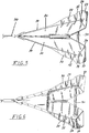
- each of the opposed flukes 20,30 as shown more clearly in Fig. 2 , has a down-turned leading end.
- the penetrating effect of the overall anchor is enhanced, with the weight of that overall anchor being concentrated at that leading end 26 for purposes of penetration of any given holding.
- each free edge thereof will be other than blunt, thereby constituting a scraping, cutting or digging surface or means for the overall anchor. This significantly enhances the ease of penetration of an anchor in accordance with the present invention, when compared with the prior art anchors.
- a spreader bar 50 extends between the respective flukes 20,30, to add extra strength to the overall anchor.
- such preferably includes an arm portion 110, extending relatively upwardly from, and substantially normally to, the base member 10.
- That arm portion 110 is preferably of a continuously reducing width dimension along the length thereof, with the uppermost edge 120 thereof being of a substantially arcuate configuration, with there being no flattened or straight sections along the length thereof.
- At or in the vicinity of the free end of the arm portion 110 there will be provided means, as for example a through-bore or aperture 130, for receiving and releasably retaining a chain, cable or rope for/of said anchor (not shown).
- the present invention seeks to provide an anchor which exhibits greater penetration regardless of the nature of the holding. This is achieved by having substantially all free edges of the flukes 20,30, as well as the extensions 22,23,32 and 33 being capable of a cutting, scraping or digging action. All such free edges are shaped to be other than blunt. The fact that the free edges are other than blunt - in other words sharpened or come to a point - gives rise to a chiselling effect, which allows ready and rapid entry into/penetration of any type of holding or substrate.
- the shank member 100 Insofar as the shank member 100 is concerned, the fact that such is in the form of a substantially arcuate member having a decreasing width dimension along the length thereof means that, if the anchor is in a rolled-over position, there will be effective point contact with the surface of the holding, rather than line contact as would be the case with anchors with conventional shank members. Such assists in encouraging an overturned anchor to right itself or assume its correct position. In a practical sense, even if to all intents and purposes no weight or load is imposed on the toe or leading end 26 of the overall anchor, the anchor will still roll over. In engineering terms the radiused/shaped shank member 100 has its effective centre of gravity disposed closer to the base member 10, this when compared with the prior art arrangements.
- Such a radiused/shaped shank member 100 also exhibits less weight when compared with its equivalent conventional anchor.
- the use of the radiused/shaped shank member 100 means that the overall anchor does not rely on the actual weight of the shank member 100 to ensure rolling.
- the present applicant's arrangement it is possible to lower the throat opening - by definition the angle subtended by the plane of the shank member 100 and the centreline of the base member 10 - this giving rise to an improved capacity for bedding in, even where a hard bottom or holding is involved.
- the step or shoulder 140 provided in the shank member 100 serves as a roller stop, to prevent the anchor from hitting its associated boat when winched in or onto a bowsprit or the like.
- each fluke 20,30 further assists in bedding in of the anchor, the effect being that the overall weight of the anchor, or more correctly the tail of the anchor, is of little significance in terms of righting an up-turned anchor.
- the capacity for utilizing a reduced throat opening or angle means that, in practical terms, more force is capable of being applied through the toe or leading end 26 of the anchor, whereby to allow the anchor to more easily penetrate even harder materials, this again in marked contrast to prior art anchor arrangements with conventional shank members, which suffer from a disadvantage in terms of decreased efficiency of embedment when the holding is formed from harder materials.
- the throat opening or throat angle has been found to have an influence on the rate of ascent/descent of an anchor.
- a plough anchor for example, if the toe or leading end strikes something harsh - in the holding - the angle of descent will become steeper.
- an anchor in accordance with the present invention since a reduced throat opening or angle is possible there can be exercised greater control over the angle of descent.
- the anchor in accordance with the present invention exhibits a unique geometry.
- the working relationship between the overall shape/geometry and the front or leading end 26 is not as significant or important.
- the present applicant's anchor is not as reliant on toe weight to ensure righting from a rolled-over position.
- the arcuate shape exhibited by the shank member 100 is in itself responsible for imparting enhanced strength capabilities thereto.
- the apertures 25 in fact function to reduce resistance, allowing water to be sucked therethrough. That in turn acts to prevent or reduce the possibility of mud or the like material compacting, in fact allowing such mud or the like material to slide off the overall anchor, assisting in further driving in or penetration of the overall anchor.
- the mud or the like being removed slides over the surface of the flukes 20,30, and water is sucked through the apertures 25. Compressive forces generated assist in movement of mud and other material.
- the rear extensions 23,33 - also to be referred to as negative flukes - have a significant effect on penetration. This creates what can be referred to as a compression lock, which favours the rate of descent and extent of penetration.
- the shaped rear end of each fluke 20,30 functions to further compress any substrate or material in a relative upward direction, herein further enhancing the extent of penetration. It has been found that the very existence of these rear extensions 23,33, let alone their actual configuration, acts to prevent the anchor from ploughing. In that regard it should be understood that, with a plough anchor - material is pushed outwardly and upwardly from about that region/location on the overall anchor where the shank member is attached to/with the base member or fluke. In contrast thereto, with an anchor in accordance with the present invention such compression takes place at the very rear of the anchor. This lack of ploughing effect is extremely useful in terms of avoiding/minimizing unwanted description of or damage to any given holding.
- the apertures 25, which may be provided in the principal planar portion of each fluke 20,30, as well as in the respective lateral and rear extensions 22,23,32 and 33, allow movement of water therethrough, thereby reducing friction/resistance and at the same time the flow of water seems to substantially prevent mud or other loose material from adhering to the surface of the flukes 20,30.
- the anchor in accordance with the present invention with its convex base member - made up of flukes 20,30 and lateral and rear extensions 22,32,23,33, and with all free edges constituting potential cutting or digging surfaces, exhibits tremendous/enhanced holding power, especially in holding comprising loose material.
- the overall anchor exhibits greater penetration ability, even with holdings of a hard material.
- the secondary flukes or lateral extensions 22,32 by being preferably of a substantially concave rather than convex shape - as distinct from the base member - exhibit less resistance to penetration, further enhancing the effectiveness of the overall anchor.
- the rear extensions - or negative flukes 23,33 - create compressive loads, in the result limiting the extent of travel of the overall anchor in a given holding. This means that the anchor cannot penetrate so deeply as to make release difficult, if not impossible. Further, and by reason of the fact that the rear extensions 23,33 project outwardly from/to the rear of the anchor, they assist in building up of pressure/load to drive the toe or leading end 26 of the anchor more easily into the holding.
- leading end, toe or breaker head 26 of the present anchor is of a substantially convex shape, further enhancing the cutting effect.
- the substantially convex shape of the base member extends well beyond the breaker head or leading end or toe 26 to the rear of the anchor.
- the respective lateral and rear extensions 22, 32, 23, 33 give rise to a concave shape, functioning to force material being separated from the holding in a rearward direction, to enhance overall holding power.
- enhanced compressive forces due to the unique geometry of the base member 10 produce unrivalled holding power - when compared with the prior art - once an anchor has buried itself.
- the anchor is further designed for side entry, when it is for example lying on its side, which may sometimes be the case.
- the shape and location of the lateral and rear extensions (flukes) 22, 32, 23, 33 not only prevent the anchor from turning over on its back, but also gives rise to significant drag at the extreme rear end/edge. This drag imparts greater pressure/load on the breaker head/toe 26, encouraging further penetration. This is especially important when the holding is formed from harder material.
- delta-type anchors have enjoyed usage for a significant period of time.
- Such known delta-type anchors have been found to suffer from a potentially serious drawback, more specifically a tendency to impact on or hit the hull of the boat when being drawn in, giving rise to unwanted damage.
- the anchor in accordance with the present invention being of a lower trajectory when compared with the prior art, can in no way impact on the boat.
- an anchor in accordance with the present invention further includes means to assist in re-setting of the anchor, as and if necessary.
- the shank member 100 includes a shaped slot extending longitudinally thereof, such slot being adapted to receive, and preferably releasably retain, a shackle or the like means, as for example a D-shackle.
- the anchor in accordance with the present invention is intended to be embedded in the relevant holding. In the instance, however, of the anchor 1 becoming disengaged from its holding, then the D-shackle will act to run along the slot from one end to the other, until such time as it impacts with the end thereof. In that regard it should be understood that, whilst this procedure of course occupies a finite time, in real terms the D-shackle impacts with the end of the slot with quite a substantial force.
- the anchor in accordance with the present invention is especially suited for use in holdings which involve or include weeds or the like.
- the extended cutting edges as provided by the extensions 22, 23, 32 and 33, allow for improved cutting through weed, kelp or the like.
- the cutting edges or surfaces provided by the associated flanges 20, 30 and extensions 22, 32 are substantially concave from front to back (toe end to rear) of the overall anchor.
- Prior art anchors traditionally include a weighted tip, such being achieved by either the use of lead or the like, with the degree of extra weighting being varied dependent on the size of the overall anchor, and also on its intended use. In contrast thereto, no additional weighting is required with the anchor in accordance with the present invention.
- the relationship (geometric and physical) existing between the negative flukes 23, 33 and the arcuate shank member 100 reduces the need for additional weighting when compared with, for example, prior art delta-type anchors.
- the base member and shank member of the anchor of the present invention will be of substantially the same weight. There should be no need for the tip or leading end of the anchor, or the overall anchor itself, to utilize or need any form of additional weighting. That said, the anchor in accordance with the present invention has been found to bed-in, dig in or penetrate any holding much quicker, easier and better (meaning deeper) than conventional anchors in accordance with the known art.
- the secondary flukes or extensions subtend a slightly negative angle, pointing inwardly towards the anchor rather than outwardly and away from the anchor. Compression of material making up the holding takes place behind these flukes or extensions.
- An anchor in accordance with the invention relies on a tunneling anchor, rather than the ploughing action attributable to conventional anchors. This in turn means less disruption to the holding, an extremely desirable result for the environment.
- the existence of the lateral and rear extensions on the base of the present anchor and the shape and configuration thereof, means that the overall anchor is loaded from the rear, with greater pressure/load therefrom to be imparted to the tip or leading end.
Landscapes
- Chemical & Material Sciences (AREA)
- Engineering & Computer Science (AREA)
- Combustion & Propulsion (AREA)
- Mechanical Engineering (AREA)
- Ocean & Marine Engineering (AREA)
- Piles And Underground Anchors (AREA)
Claims (11)
- Ancre améliorée comprenant un élément de base (10), une extrémité de celui-ci constituant une extrémité avant de ladite ancre et étant adaptée pour aider à l'ancrage / plongement de ladite ancre selon une position donnée et l'autre extrémité de celui-ci constituant une extrémité arrière de l'ancre, et un élément de tige (100) attaché fixement audit élément de base (10), ledit élément de tige (100) étant adapté, en utilisation, à recevoir et retenir de manière libérable au moins une ligne d'ancrage, une corde ou un câble, dans laquelle ledit élément de base (10) a une forme ou une configuration sensiblement triangulaire lorsqu'elle est regardée dans le plan et avec un sommet de ladite forme triangulaire constituant ladite extrémité avant de ladite ancre, et dans laquelle ledit élément de base (10) comprend des première et seconde pattes (20, 30) opposées respectives, chacune desdites pattes (20, 30) étant sensiblement de forme triangulaire lorsqu'elle est regardée dans le plan, lesdites pattes (20, 30) opposées étant disposées angulairement l'une par rapport à l'autre et étant jointes le long d'une ligne qui constitue un axe longitudinal central pour ledit élément de base (10), dans laquelle chacune des première et seconde pattes (20, 30) est sensiblement de forme plane de l'extrémité avant vers un prolongement arrière (23, 33) sensiblement plan qui fait saillie à partir d'un bord arrière de ladite patte (20, 30) angulairement et en dehors du plan de celui-ci vers une surface supérieure de ladite patte (20, 30), ledit prolongement arrière (23, 33) s'étendant vers l'arrière de l'ancre, caractérisée en ce que chaque bord libre de chaque patte (20, 30) est autre qu'émoussé de façon à constituer une coupe, un creux ou un moyen de raclage pour aider ledit plongement de ladite ancre, l'élément de base (10) contenant au moins une discontinuité, trou, fente ou ouverture (25) et un bord avant étagé vers le bas ou orteil (26), dans laquelle chacune des première et seconde pattes (20, 30) présente un prolongement latéral (22, 32) en saillie à l'extrémité arrière de l'élément de base à partir du bord libre (21, 31) de celui-ci associé à un angle par rapport à celui-ci et en dehors du plan de celui-ci, et dans laquelle chaque prolongement latéral (22, 32) respectif est relié le long d'un bord dudit prolongement arrière (23, 33).
- Ancre selon la revendication 1, dans laquelle ledit prolongement latéral (22, 32) s'étend le long d'au moins une partie du bord libre (21, 31) de la patte (20, 30) associée, avec des bords libres desdits prolongements étant d'une forme autre qu'émoussée.
- Ancre selon la revendication 2, dans laquelle ledit prolongement arrière (22, 32) dépend d'un angle à l'arrière dudit élément de base (10), avec des bords libres de ceux-ci étant d'une forme autre qu'émoussée.
- Ancre selon la revendication 3, dans laquelle ledit élément de tige (100) est sous la forme d'un élément allongé (110), fixé audit élément de base (10) et s'étendant sensiblement perpendiculairement à celui-ci, ledit élément allongé (10) étant d'une dimension d'épaisseur diminuant progressivement le long de la longueur de celui-ci.
- Ancre selon la revendication 4, dans laquelle ledit élément de tige (100) comporte, au niveau ou au voisinage de l'emplacement de jonction de celui-ci audit élément de base, une discontinuité ou une épaule (140).
- Ancre selon la revendication 5, dans laquelle ledit élément de tige (100) est sensiblement en forme d'arc.
- Ancre selon la revendication 6, dans laquelle chaque patte (20, 30) à un bord avant étagé vers le bas.
- Ancre selon la revendication 4, dans laquelle le bord ou la surface supérieure dudit élément allongé (110) est d'une forme autre qu'émoussée, ledit élément allongé (110) étant d'une configuration sensiblement en forme d'arc.
- Ancre selon la revendication 8, dans laquelle ledit élément allongé (110) comporte, au niveau ou au voisinage de son extrémité libre, au moins une ouverture (130) adaptée pour recevoir et retenir de façon libérable une chaine, un câble ou corde à / de ladite ancre.
- Ancre selon la revendication 1, comportant une ou plusieurs discontinuités, trous, fentes ou ouvertures (25) s'étendant vers chacune de ladite patte (20, 30).
- Ancre selon la revendication 10, dans laquelle au moins une discontinuité, trou, fente ou ouverture (25) de ladite patte (20, 30) s'étend selon un prolongement latéral adjacent ou un prolongement arrière adjacent (22, 23, 32, 33).
Applications Claiming Priority (2)
| Application Number | Priority Date | Filing Date | Title |
|---|---|---|---|
| AU2007901627A AU2007901627A0 (en) | 2007-03-27 | Improved anchor | |
| PCT/AU2008/000440 WO2008116272A1 (fr) | 2007-03-27 | 2008-03-27 | Ancre améliorée |
Publications (3)
| Publication Number | Publication Date |
|---|---|
| EP2129573A1 EP2129573A1 (fr) | 2009-12-09 |
| EP2129573A4 EP2129573A4 (fr) | 2013-02-20 |
| EP2129573B1 true EP2129573B1 (fr) | 2016-12-07 |
Family
ID=39787977
Family Applications (1)
| Application Number | Title | Priority Date | Filing Date |
|---|---|---|---|
| EP08733277.1A Active EP2129573B1 (fr) | 2007-03-27 | 2008-03-27 | Ancre améliorée |
Country Status (5)
| Country | Link |
|---|---|
| US (1) | US8205569B2 (fr) |
| EP (1) | EP2129573B1 (fr) |
| AU (1) | AU2008232320B2 (fr) |
| NZ (1) | NZ579932A (fr) |
| WO (1) | WO2008116272A1 (fr) |
Families Citing this family (10)
| Publication number | Priority date | Publication date | Assignee | Title |
|---|---|---|---|---|
| JP4678624B1 (ja) * | 2010-07-14 | 2011-04-27 | 義明 白輪地 | アンカー |
| USD676796S1 (en) * | 2011-11-09 | 2013-02-26 | Manson Anchors Limited | Anchor |
| USD766394S1 (en) | 2015-03-20 | 2016-09-13 | Isla Llc | Sun shelter |
| US9562368B2 (en) | 2014-03-21 | 2017-02-07 | Isla Llc | Collapsible sun shelter |
| US9802678B2 (en) * | 2014-06-27 | 2017-10-31 | Tim Orsello | Anchor systems and methods |
| USD852917S1 (en) | 2015-03-20 | 2019-07-02 | Isla Llc | Sun shelter |
| USD861571S1 (en) * | 2016-12-09 | 2019-10-01 | Charles J Ceccarelli | Marine anchor fluke |
| USD827547S1 (en) * | 2016-12-14 | 2018-09-04 | Charles J Ceccarelli | Marine anchor spade |
| CN113753178B (zh) * | 2021-09-28 | 2022-12-27 | 九江职院船舶与海洋工程技术有限公司 | 一种用于船舶防卡的船锚结构 |
| USD1065002S1 (en) * | 2023-03-08 | 2025-03-04 | Stevlos B.V. | Anchor |
Family Cites Families (13)
| Publication number | Priority date | Publication date | Assignee | Title |
|---|---|---|---|---|
| NL163474C (nl) * | 1974-11-06 | 1980-09-15 | Petrus Josef Klaren | Stokloos anker. |
| CA1278725C (fr) * | 1985-09-27 | 1991-01-08 | Rob Van Den Haak | Ancre |
| GB8808373D0 (en) * | 1988-04-09 | 1988-05-11 | Simpson-Lawrence Ltd | Marine anchor |
| US5188055A (en) * | 1992-01-08 | 1993-02-23 | Kershner Gary P | Adjustable boat anchor |
| US5855181A (en) * | 1997-02-14 | 1999-01-05 | Oxford; Sefton M.D. | Fixed shank plow anchor |
| NZ331750A (en) * | 1997-09-10 | 2000-01-28 | William Francis Rex | Anchor comprises a base, a shank and stabilizing means |
| US6148758A (en) * | 1998-02-04 | 2000-11-21 | Electromechanical Research Laboratories, Inc. | Boat anchor |
| US6332423B1 (en) * | 2001-02-09 | 2001-12-25 | Kingston Anchors Limited | Marine anchor |
| FR2827832B1 (fr) * | 2001-07-26 | 2003-10-31 | Plastimo France | Ancre de type charrue |
| US6390011B1 (en) * | 2001-09-07 | 2002-05-21 | Jack Goodman | Smart anchor |
| AUPS301402A0 (en) * | 2002-06-18 | 2002-07-11 | Francis, Rex William | Improvements in anchors |
| EP1462357B1 (fr) * | 2003-03-27 | 2007-09-12 | Alain Poiraud | Ancre asymétrique sans ballast |
| USD556666S1 (en) * | 2006-02-16 | 2007-12-04 | Manson Anchors Limited | Anchor |
-
2008
- 2008-03-27 WO PCT/AU2008/000440 patent/WO2008116272A1/fr not_active Ceased
- 2008-03-27 US US12/532,889 patent/US8205569B2/en active Active
- 2008-03-27 EP EP08733277.1A patent/EP2129573B1/fr active Active
- 2008-03-27 AU AU2008232320A patent/AU2008232320B2/en active Active
- 2008-03-27 NZ NZ579932A patent/NZ579932A/en unknown
Non-Patent Citations (1)
| Title |
|---|
| None * |
Also Published As
| Publication number | Publication date |
|---|---|
| EP2129573A4 (fr) | 2013-02-20 |
| AU2008232320A1 (en) | 2008-10-02 |
| US20100058968A1 (en) | 2010-03-11 |
| WO2008116272A1 (fr) | 2008-10-02 |
| US8205569B2 (en) | 2012-06-26 |
| AU2008232320B2 (en) | 2012-08-09 |
| NZ579932A (en) | 2012-07-27 |
| EP2129573A1 (fr) | 2009-12-09 |
Similar Documents
| Publication | Publication Date | Title |
|---|---|---|
| EP2129573B1 (fr) | Ancre améliorée | |
| AU628047B2 (en) | Marine anchor | |
| EP0020152B1 (fr) | Verge d'ancre | |
| US4869193A (en) | Anchor | |
| CA2488506C (fr) | Ancre pourvue d'une deuxieme patte de dimensions inferieures | |
| US5970902A (en) | Anchors | |
| GB2035242A (en) | Anchor | |
| US4397257A (en) | Sea anchor in particular for large ships | |
| US20050066870A1 (en) | Ground anchors using tines and compression plate | |
| JP3236615B2 (ja) | 改良した船用アンカー | |
| US6390011B1 (en) | Smart anchor | |
| US2677343A (en) | Anchor | |
| JP3177807U (ja) | 岩場砂地兼用アンカー | |
| AU734943B2 (en) | Improvements in anchors | |
| US3902446A (en) | Anchor | |
| AU2003240308B2 (en) | Anchor with smaller second fluke | |
| AU2018256526B2 (en) | Anchor system | |
| GB2091188A (en) | Single fluke anchor | |
| GB2183580A (en) | Anchor | |
| JPH043359B2 (fr) |
Legal Events
| Date | Code | Title | Description |
|---|---|---|---|
| PUAI | Public reference made under article 153(3) epc to a published international application that has entered the european phase |
Free format text: ORIGINAL CODE: 0009012 |
|
| 17P | Request for examination filed |
Effective date: 20090925 |
|
| AK | Designated contracting states |
Kind code of ref document: A1 Designated state(s): AT BE BG CH CY CZ DE DK EE ES FI FR GB GR HR HU IE IS IT LI LT LU LV MC MT NL NO PL PT RO SE SI SK TR |
|
| DAX | Request for extension of the european patent (deleted) | ||
| REG | Reference to a national code |
Ref country code: DE Ref legal event code: R079 Ref document number: 602008047751 Country of ref document: DE Free format text: PREVIOUS MAIN CLASS: B63B0021300000 Ipc: B63B0021320000 |
|
| A4 | Supplementary search report drawn up and despatched |
Effective date: 20130117 |
|
| RIC1 | Information provided on ipc code assigned before grant |
Ipc: B63B 21/32 20060101AFI20130111BHEP |
|
| GRAP | Despatch of communication of intention to grant a patent |
Free format text: ORIGINAL CODE: EPIDOSNIGR1 |
|
| INTG | Intention to grant announced |
Effective date: 20160630 |
|
| GRAS | Grant fee paid |
Free format text: ORIGINAL CODE: EPIDOSNIGR3 |
|
| GRAA | (expected) grant |
Free format text: ORIGINAL CODE: 0009210 |
|
| AK | Designated contracting states |
Kind code of ref document: B1 Designated state(s): AT BE BG CH CY CZ DE DK EE ES FI FR GB GR HR HU IE IS IT LI LT LU LV MC MT NL NO PL PT RO SE SI SK TR |
|
| REG | Reference to a national code |
Ref country code: GB Ref legal event code: FG4D |
|
| REG | Reference to a national code |
Ref country code: CH Ref legal event code: EP Ref country code: AT Ref legal event code: REF Ref document number: 851427 Country of ref document: AT Kind code of ref document: T Effective date: 20161215 |
|
| REG | Reference to a national code |
Ref country code: IE Ref legal event code: FG4D |
|
| REG | Reference to a national code |
Ref country code: DE Ref legal event code: R096 Ref document number: 602008047751 Country of ref document: DE |
|
| REG | Reference to a national code |
Ref country code: FR Ref legal event code: PLFP Year of fee payment: 10 |
|
| PG25 | Lapsed in a contracting state [announced via postgrant information from national office to epo] |
Ref country code: LV Free format text: LAPSE BECAUSE OF FAILURE TO SUBMIT A TRANSLATION OF THE DESCRIPTION OR TO PAY THE FEE WITHIN THE PRESCRIBED TIME-LIMIT Effective date: 20161207 |
|
| REG | Reference to a national code |
Ref country code: LT Ref legal event code: MG4D |
|
| REG | Reference to a national code |
Ref country code: NL Ref legal event code: MP Effective date: 20161207 |
|
| PG25 | Lapsed in a contracting state [announced via postgrant information from national office to epo] |
Ref country code: GR Free format text: LAPSE BECAUSE OF FAILURE TO SUBMIT A TRANSLATION OF THE DESCRIPTION OR TO PAY THE FEE WITHIN THE PRESCRIBED TIME-LIMIT Effective date: 20170308 Ref country code: LT Free format text: LAPSE BECAUSE OF FAILURE TO SUBMIT A TRANSLATION OF THE DESCRIPTION OR TO PAY THE FEE WITHIN THE PRESCRIBED TIME-LIMIT Effective date: 20161207 Ref country code: NO Free format text: LAPSE BECAUSE OF FAILURE TO SUBMIT A TRANSLATION OF THE DESCRIPTION OR TO PAY THE FEE WITHIN THE PRESCRIBED TIME-LIMIT Effective date: 20170307 Ref country code: SE Free format text: LAPSE BECAUSE OF FAILURE TO SUBMIT A TRANSLATION OF THE DESCRIPTION OR TO PAY THE FEE WITHIN THE PRESCRIBED TIME-LIMIT Effective date: 20161207 |
|
| REG | Reference to a national code |
Ref country code: AT Ref legal event code: MK05 Ref document number: 851427 Country of ref document: AT Kind code of ref document: T Effective date: 20161207 |
|
| PG25 | Lapsed in a contracting state [announced via postgrant information from national office to epo] |
Ref country code: FI Free format text: LAPSE BECAUSE OF FAILURE TO SUBMIT A TRANSLATION OF THE DESCRIPTION OR TO PAY THE FEE WITHIN THE PRESCRIBED TIME-LIMIT Effective date: 20161207 Ref country code: ES Free format text: LAPSE BECAUSE OF FAILURE TO SUBMIT A TRANSLATION OF THE DESCRIPTION OR TO PAY THE FEE WITHIN THE PRESCRIBED TIME-LIMIT Effective date: 20161207 Ref country code: HR Free format text: LAPSE BECAUSE OF FAILURE TO SUBMIT A TRANSLATION OF THE DESCRIPTION OR TO PAY THE FEE WITHIN THE PRESCRIBED TIME-LIMIT Effective date: 20161207 |
|
| PG25 | Lapsed in a contracting state [announced via postgrant information from national office to epo] |
Ref country code: NL Free format text: LAPSE BECAUSE OF FAILURE TO SUBMIT A TRANSLATION OF THE DESCRIPTION OR TO PAY THE FEE WITHIN THE PRESCRIBED TIME-LIMIT Effective date: 20161207 |
|
| PG25 | Lapsed in a contracting state [announced via postgrant information from national office to epo] |
Ref country code: RO Free format text: LAPSE BECAUSE OF FAILURE TO SUBMIT A TRANSLATION OF THE DESCRIPTION OR TO PAY THE FEE WITHIN THE PRESCRIBED TIME-LIMIT Effective date: 20161207 Ref country code: SK Free format text: LAPSE BECAUSE OF FAILURE TO SUBMIT A TRANSLATION OF THE DESCRIPTION OR TO PAY THE FEE WITHIN THE PRESCRIBED TIME-LIMIT Effective date: 20161207 Ref country code: EE Free format text: LAPSE BECAUSE OF FAILURE TO SUBMIT A TRANSLATION OF THE DESCRIPTION OR TO PAY THE FEE WITHIN THE PRESCRIBED TIME-LIMIT Effective date: 20161207 Ref country code: CZ Free format text: LAPSE BECAUSE OF FAILURE TO SUBMIT A TRANSLATION OF THE DESCRIPTION OR TO PAY THE FEE WITHIN THE PRESCRIBED TIME-LIMIT Effective date: 20161207 Ref country code: IS Free format text: LAPSE BECAUSE OF FAILURE TO SUBMIT A TRANSLATION OF THE DESCRIPTION OR TO PAY THE FEE WITHIN THE PRESCRIBED TIME-LIMIT Effective date: 20170407 |
|
| PG25 | Lapsed in a contracting state [announced via postgrant information from national office to epo] |
Ref country code: PL Free format text: LAPSE BECAUSE OF FAILURE TO SUBMIT A TRANSLATION OF THE DESCRIPTION OR TO PAY THE FEE WITHIN THE PRESCRIBED TIME-LIMIT Effective date: 20161207 Ref country code: BE Free format text: LAPSE BECAUSE OF FAILURE TO SUBMIT A TRANSLATION OF THE DESCRIPTION OR TO PAY THE FEE WITHIN THE PRESCRIBED TIME-LIMIT Effective date: 20161207 Ref country code: AT Free format text: LAPSE BECAUSE OF FAILURE TO SUBMIT A TRANSLATION OF THE DESCRIPTION OR TO PAY THE FEE WITHIN THE PRESCRIBED TIME-LIMIT Effective date: 20161207 Ref country code: PT Free format text: LAPSE BECAUSE OF FAILURE TO SUBMIT A TRANSLATION OF THE DESCRIPTION OR TO PAY THE FEE WITHIN THE PRESCRIBED TIME-LIMIT Effective date: 20170407 Ref country code: BG Free format text: LAPSE BECAUSE OF FAILURE TO SUBMIT A TRANSLATION OF THE DESCRIPTION OR TO PAY THE FEE WITHIN THE PRESCRIBED TIME-LIMIT Effective date: 20170307 |
|
| REG | Reference to a national code |
Ref country code: DE Ref legal event code: R097 Ref document number: 602008047751 Country of ref document: DE |
|
| REG | Reference to a national code |
Ref country code: DE Ref legal event code: R119 Ref document number: 602008047751 Country of ref document: DE |
|
| PLBE | No opposition filed within time limit |
Free format text: ORIGINAL CODE: 0009261 |
|
| STAA | Information on the status of an ep patent application or granted ep patent |
Free format text: STATUS: NO OPPOSITION FILED WITHIN TIME LIMIT |
|
| REG | Reference to a national code |
Ref country code: CH Ref legal event code: PL |
|
| 26N | No opposition filed |
Effective date: 20170908 |
|
| PG25 | Lapsed in a contracting state [announced via postgrant information from national office to epo] |
Ref country code: MC Free format text: LAPSE BECAUSE OF FAILURE TO SUBMIT A TRANSLATION OF THE DESCRIPTION OR TO PAY THE FEE WITHIN THE PRESCRIBED TIME-LIMIT Effective date: 20161207 Ref country code: DK Free format text: LAPSE BECAUSE OF FAILURE TO SUBMIT A TRANSLATION OF THE DESCRIPTION OR TO PAY THE FEE WITHIN THE PRESCRIBED TIME-LIMIT Effective date: 20161207 Ref country code: SI Free format text: LAPSE BECAUSE OF FAILURE TO SUBMIT A TRANSLATION OF THE DESCRIPTION OR TO PAY THE FEE WITHIN THE PRESCRIBED TIME-LIMIT Effective date: 20161207 |
|
| REG | Reference to a national code |
Ref country code: IE Ref legal event code: MM4A |
|
| PG25 | Lapsed in a contracting state [announced via postgrant information from national office to epo] |
Ref country code: DE Free format text: LAPSE BECAUSE OF NON-PAYMENT OF DUE FEES Effective date: 20171003 Ref country code: LU Free format text: LAPSE BECAUSE OF NON-PAYMENT OF DUE FEES Effective date: 20170327 |
|
| PG25 | Lapsed in a contracting state [announced via postgrant information from national office to epo] |
Ref country code: CH Free format text: LAPSE BECAUSE OF NON-PAYMENT OF DUE FEES Effective date: 20170331 Ref country code: LI Free format text: LAPSE BECAUSE OF NON-PAYMENT OF DUE FEES Effective date: 20170331 Ref country code: IE Free format text: LAPSE BECAUSE OF NON-PAYMENT OF DUE FEES Effective date: 20170327 |
|
| REG | Reference to a national code |
Ref country code: FR Ref legal event code: PLFP Year of fee payment: 11 |
|
| PG25 | Lapsed in a contracting state [announced via postgrant information from national office to epo] |
Ref country code: MT Free format text: LAPSE BECAUSE OF NON-PAYMENT OF DUE FEES Effective date: 20170327 |
|
| PGFP | Annual fee paid to national office [announced via postgrant information from national office to epo] |
Ref country code: FR Payment date: 20190329 Year of fee payment: 12 |
|
| PG25 | Lapsed in a contracting state [announced via postgrant information from national office to epo] |
Ref country code: HU Free format text: LAPSE BECAUSE OF FAILURE TO SUBMIT A TRANSLATION OF THE DESCRIPTION OR TO PAY THE FEE WITHIN THE PRESCRIBED TIME-LIMIT; INVALID AB INITIO Effective date: 20080327 |
|
| PGFP | Annual fee paid to national office [announced via postgrant information from national office to epo] |
Ref country code: IT Payment date: 20190329 Year of fee payment: 12 |
|
| PG25 | Lapsed in a contracting state [announced via postgrant information from national office to epo] |
Ref country code: CY Free format text: LAPSE BECAUSE OF NON-PAYMENT OF DUE FEES Effective date: 20161207 |
|
| PG25 | Lapsed in a contracting state [announced via postgrant information from national office to epo] |
Ref country code: TR Free format text: LAPSE BECAUSE OF FAILURE TO SUBMIT A TRANSLATION OF THE DESCRIPTION OR TO PAY THE FEE WITHIN THE PRESCRIBED TIME-LIMIT Effective date: 20161207 |
|
| PG25 | Lapsed in a contracting state [announced via postgrant information from national office to epo] |
Ref country code: FR Free format text: LAPSE BECAUSE OF NON-PAYMENT OF DUE FEES Effective date: 20200331 |
|
| PG25 | Lapsed in a contracting state [announced via postgrant information from national office to epo] |
Ref country code: IT Free format text: LAPSE BECAUSE OF NON-PAYMENT OF DUE FEES Effective date: 20200327 |
|
| PGFP | Annual fee paid to national office [announced via postgrant information from national office to epo] |
Ref country code: GB Payment date: 20260223 Year of fee payment: 19 |