EP2129708B1 - Composant rapporté pour réservoir de carburant et procédé de fabrication d'un composant rapporté pour réservoir de carburant - Google Patents
Composant rapporté pour réservoir de carburant et procédé de fabrication d'un composant rapporté pour réservoir de carburant Download PDFInfo
- Publication number
- EP2129708B1 EP2129708B1 EP08718013A EP08718013A EP2129708B1 EP 2129708 B1 EP2129708 B1 EP 2129708B1 EP 08718013 A EP08718013 A EP 08718013A EP 08718013 A EP08718013 A EP 08718013A EP 2129708 B1 EP2129708 B1 EP 2129708B1
- Authority
- EP
- European Patent Office
- Prior art keywords
- plastic
- fuel tank
- component
- region
- mixture
- Prior art date
- Legal status (The legal status is an assumption and is not a legal conclusion. Google has not performed a legal analysis and makes no representation as to the accuracy of the status listed.)
- Not-in-force
Links
- 239000002828 fuel tank Substances 0.000 title claims abstract description 63
- 238000004519 manufacturing process Methods 0.000 title claims description 22
- 229920003023 plastic Polymers 0.000 claims abstract description 121
- 239000004033 plastic Substances 0.000 claims abstract description 121
- 239000000203 mixture Substances 0.000 claims abstract description 43
- 239000000446 fuel Substances 0.000 claims abstract description 35
- 238000005304 joining Methods 0.000 claims description 45
- 239000004698 Polyethylene Substances 0.000 claims description 30
- 229920001577 copolymer Polymers 0.000 claims description 30
- 229920000573 polyethylene Polymers 0.000 claims description 30
- 239000004952 Polyamide Substances 0.000 claims description 29
- 229920002647 polyamide Polymers 0.000 claims description 29
- 239000000463 material Substances 0.000 claims description 14
- 238000000034 method Methods 0.000 claims description 11
- -1 polyethylene Polymers 0.000 claims description 11
- 239000011248 coating agent Substances 0.000 claims description 8
- 238000000576 coating method Methods 0.000 claims description 8
- 238000001746 injection moulding Methods 0.000 claims description 7
- 238000002347 injection Methods 0.000 claims description 5
- 239000007924 injection Substances 0.000 claims description 5
- 238000009832 plasma treatment Methods 0.000 claims description 5
- FPYJFEHAWHCUMM-UHFFFAOYSA-N maleic anhydride Chemical group O=C1OC(=O)C=C1 FPYJFEHAWHCUMM-UHFFFAOYSA-N 0.000 claims description 4
- 238000003486 chemical etching Methods 0.000 claims description 3
- 239000007788 liquid Substances 0.000 claims description 3
- 238000009996 mechanical pre-treatment Methods 0.000 claims description 3
- 125000003504 2-oxazolinyl group Chemical group O1C(=NCC1)* 0.000 claims description 2
- 238000007334 copolymerization reaction Methods 0.000 claims description 2
- 125000003700 epoxy group Chemical group 0.000 claims description 2
- IQPQWNKOIGAROB-UHFFFAOYSA-N isocyanate group Chemical group [N-]=C=O IQPQWNKOIGAROB-UHFFFAOYSA-N 0.000 claims description 2
- 239000007787 solid Substances 0.000 claims description 2
- 239000003795 chemical substances by application Substances 0.000 claims 8
- 238000007788 roughening Methods 0.000 claims 1
- 238000003466 welding Methods 0.000 claims 1
- HIZCTWCPHWUPFU-UHFFFAOYSA-N Glycerol tribenzoate Chemical compound C=1C=CC=CC=1C(=O)OCC(OC(=O)C=1C=CC=CC=1)COC(=O)C1=CC=CC=C1 HIZCTWCPHWUPFU-UHFFFAOYSA-N 0.000 description 12
- 239000007789 gas Substances 0.000 description 10
- 230000008961 swelling Effects 0.000 description 8
- 239000012815 thermoplastic material Substances 0.000 description 8
- 239000000654 additive Substances 0.000 description 6
- 238000013022 venting Methods 0.000 description 6
- 150000002500 ions Chemical class 0.000 description 5
- XKRFYHLGVUSROY-UHFFFAOYSA-N Argon Chemical compound [Ar] XKRFYHLGVUSROY-UHFFFAOYSA-N 0.000 description 4
- 239000012298 atmosphere Substances 0.000 description 4
- 230000008901 benefit Effects 0.000 description 4
- 229910052756 noble gas Inorganic materials 0.000 description 4
- 150000001875 compounds Chemical class 0.000 description 3
- 239000000314 lubricant Substances 0.000 description 3
- 210000004072 lung Anatomy 0.000 description 3
- 238000002156 mixing Methods 0.000 description 3
- 239000000049 pigment Substances 0.000 description 3
- 230000009257 reactivity Effects 0.000 description 3
- 239000003381 stabilizer Substances 0.000 description 3
- 125000000218 acetic acid group Chemical group C(C)(=O)* 0.000 description 2
- 239000002253 acid Substances 0.000 description 2
- 229910052786 argon Inorganic materials 0.000 description 2
- 230000015572 biosynthetic process Effects 0.000 description 2
- 229910052734 helium Inorganic materials 0.000 description 2
- 239000001307 helium Substances 0.000 description 2
- SWQJXJOGLNCZEY-UHFFFAOYSA-N helium atom Chemical compound [He] SWQJXJOGLNCZEY-UHFFFAOYSA-N 0.000 description 2
- 229910052743 krypton Inorganic materials 0.000 description 2
- DNNSSWSSYDEUBZ-UHFFFAOYSA-N krypton atom Chemical compound [Kr] DNNSSWSSYDEUBZ-UHFFFAOYSA-N 0.000 description 2
- 239000002184 metal Substances 0.000 description 2
- 229910052754 neon Inorganic materials 0.000 description 2
- GKAOGPIIYCISHV-UHFFFAOYSA-N neon atom Chemical compound [Ne] GKAOGPIIYCISHV-UHFFFAOYSA-N 0.000 description 2
- 229920000728 polyester Polymers 0.000 description 2
- 229920000642 polymer Polymers 0.000 description 2
- 229920000098 polyolefin Polymers 0.000 description 2
- 238000002203 pretreatment Methods 0.000 description 2
- 230000002035 prolonged effect Effects 0.000 description 2
- 229910052704 radon Inorganic materials 0.000 description 2
- SYUHGPGVQRZVTB-UHFFFAOYSA-N radon atom Chemical compound [Rn] SYUHGPGVQRZVTB-UHFFFAOYSA-N 0.000 description 2
- 230000009467 reduction Effects 0.000 description 2
- 229910052724 xenon Inorganic materials 0.000 description 2
- FHNFHKCVQCLJFQ-UHFFFAOYSA-N xenon atom Chemical compound [Xe] FHNFHKCVQCLJFQ-UHFFFAOYSA-N 0.000 description 2
- 239000004609 Impact Modifier Substances 0.000 description 1
- 230000004913 activation Effects 0.000 description 1
- 239000002318 adhesion promoter Substances 0.000 description 1
- 239000002216 antistatic agent Substances 0.000 description 1
- 239000002800 charge carrier Substances 0.000 description 1
- 239000007799 cork Substances 0.000 description 1
- 230000001419 dependent effect Effects 0.000 description 1
- 239000000975 dye Substances 0.000 description 1
- 239000003995 emulsifying agent Substances 0.000 description 1
- 239000003063 flame retardant Substances 0.000 description 1
- 239000012634 fragment Substances 0.000 description 1
- 238000005246 galvanizing Methods 0.000 description 1
- 238000010438 heat treatment Methods 0.000 description 1
- 230000007774 longterm Effects 0.000 description 1
- 238000000465 moulding Methods 0.000 description 1
- 230000007935 neutral effect Effects 0.000 description 1
- 238000005457 optimization Methods 0.000 description 1
- 239000002245 particle Substances 0.000 description 1
- 238000004023 plastic welding Methods 0.000 description 1
- 230000008092 positive effect Effects 0.000 description 1
- 230000008569 process Effects 0.000 description 1
- 238000007711 solidification Methods 0.000 description 1
- 230000008023 solidification Effects 0.000 description 1
- 239000000243 solution Substances 0.000 description 1
- 239000000126 substance Substances 0.000 description 1
- 229920001169 thermoplastic Polymers 0.000 description 1
- 239000004416 thermosoftening plastic Substances 0.000 description 1
- 230000007704 transition Effects 0.000 description 1
Images


Classifications
-
- C—CHEMISTRY; METALLURGY
- C08—ORGANIC MACROMOLECULAR COMPOUNDS; THEIR PREPARATION OR CHEMICAL WORKING-UP; COMPOSITIONS BASED THEREON
- C08J—WORKING-UP; GENERAL PROCESSES OF COMPOUNDING; AFTER-TREATMENT NOT COVERED BY SUBCLASSES C08B, C08C, C08F, C08G or C08H
- C08J5/00—Manufacture of articles or shaped materials containing macromolecular substances
- C08J5/12—Bonding of a preformed macromolecular material to the same or other solid material such as metal, glass, leather, e.g. using adhesives
- C08J5/124—Bonding of a preformed macromolecular material to the same or other solid material such as metal, glass, leather, e.g. using adhesives using adhesives based on a macromolecular component
- C08J5/128—Adhesives without diluent
-
- B—PERFORMING OPERATIONS; TRANSPORTING
- B29—WORKING OF PLASTICS; WORKING OF SUBSTANCES IN A PLASTIC STATE IN GENERAL
- B29C—SHAPING OR JOINING OF PLASTICS; SHAPING OF MATERIAL IN A PLASTIC STATE, NOT OTHERWISE PROVIDED FOR; AFTER-TREATMENT OF THE SHAPED PRODUCTS, e.g. REPAIRING
- B29C45/00—Injection moulding, i.e. forcing the required volume of moulding material through a nozzle into a closed mould; Apparatus therefor
- B29C45/16—Making multilayered or multicoloured articles
- B29C45/1657—Making multilayered or multicoloured articles using means for adhering or bonding the layers or parts to each other
-
- B—PERFORMING OPERATIONS; TRANSPORTING
- B29—WORKING OF PLASTICS; WORKING OF SUBSTANCES IN A PLASTIC STATE IN GENERAL
- B29C—SHAPING OR JOINING OF PLASTICS; SHAPING OF MATERIAL IN A PLASTIC STATE, NOT OTHERWISE PROVIDED FOR; AFTER-TREATMENT OF THE SHAPED PRODUCTS, e.g. REPAIRING
- B29C59/00—Surface shaping of articles, e.g. embossing; Apparatus therefor
- B29C59/14—Surface shaping of articles, e.g. embossing; Apparatus therefor by plasma treatment
-
- B—PERFORMING OPERATIONS; TRANSPORTING
- B29—WORKING OF PLASTICS; WORKING OF SUBSTANCES IN A PLASTIC STATE IN GENERAL
- B29C—SHAPING OR JOINING OF PLASTICS; SHAPING OF MATERIAL IN A PLASTIC STATE, NOT OTHERWISE PROVIDED FOR; AFTER-TREATMENT OF THE SHAPED PRODUCTS, e.g. REPAIRING
- B29C65/00—Joining or sealing of preformed parts, e.g. welding of plastics materials; Apparatus therefor
- B29C65/48—Joining or sealing of preformed parts, e.g. welding of plastics materials; Apparatus therefor using adhesives, i.e. using supplementary joining material; solvent bonding
- B29C65/50—Joining or sealing of preformed parts, e.g. welding of plastics materials; Apparatus therefor using adhesives, i.e. using supplementary joining material; solvent bonding using adhesive tape, e.g. thermoplastic tape; using threads or the like
- B29C65/5057—Joining or sealing of preformed parts, e.g. welding of plastics materials; Apparatus therefor using adhesives, i.e. using supplementary joining material; solvent bonding using adhesive tape, e.g. thermoplastic tape; using threads or the like positioned between the surfaces to be joined
-
- B—PERFORMING OPERATIONS; TRANSPORTING
- B29—WORKING OF PLASTICS; WORKING OF SUBSTANCES IN A PLASTIC STATE IN GENERAL
- B29C—SHAPING OR JOINING OF PLASTICS; SHAPING OF MATERIAL IN A PLASTIC STATE, NOT OTHERWISE PROVIDED FOR; AFTER-TREATMENT OF THE SHAPED PRODUCTS, e.g. REPAIRING
- B29C66/00—General aspects of processes or apparatus for joining preformed parts
- B29C66/01—General aspects dealing with the joint area or with the area to be joined
- B29C66/02—Preparation of the material, in the area to be joined, prior to joining or welding
- B29C66/028—Non-mechanical surface pre-treatments, i.e. by flame treatment, electric discharge treatment, plasma treatment, wave energy or particle radiation
-
- B—PERFORMING OPERATIONS; TRANSPORTING
- B29—WORKING OF PLASTICS; WORKING OF SUBSTANCES IN A PLASTIC STATE IN GENERAL
- B29C—SHAPING OR JOINING OF PLASTICS; SHAPING OF MATERIAL IN A PLASTIC STATE, NOT OTHERWISE PROVIDED FOR; AFTER-TREATMENT OF THE SHAPED PRODUCTS, e.g. REPAIRING
- B29C66/00—General aspects of processes or apparatus for joining preformed parts
- B29C66/01—General aspects dealing with the joint area or with the area to be joined
- B29C66/05—Particular design of joint configurations
- B29C66/10—Particular design of joint configurations particular design of the joint cross-sections
- B29C66/11—Joint cross-sections comprising a single joint-segment, i.e. one of the parts to be joined comprising a single joint-segment in the joint cross-section
- B29C66/112—Single lapped joints
-
- B—PERFORMING OPERATIONS; TRANSPORTING
- B29—WORKING OF PLASTICS; WORKING OF SUBSTANCES IN A PLASTIC STATE IN GENERAL
- B29C—SHAPING OR JOINING OF PLASTICS; SHAPING OF MATERIAL IN A PLASTIC STATE, NOT OTHERWISE PROVIDED FOR; AFTER-TREATMENT OF THE SHAPED PRODUCTS, e.g. REPAIRING
- B29C66/00—General aspects of processes or apparatus for joining preformed parts
- B29C66/01—General aspects dealing with the joint area or with the area to be joined
- B29C66/05—Particular design of joint configurations
- B29C66/10—Particular design of joint configurations particular design of the joint cross-sections
- B29C66/13—Single flanged joints; Fin-type joints; Single hem joints; Edge joints; Interpenetrating fingered joints; Other specific particular designs of joint cross-sections not provided for in groups B29C66/11 - B29C66/12
- B29C66/131—Single flanged joints, i.e. one of the parts to be joined being rigid and flanged in the joint area
-
- B—PERFORMING OPERATIONS; TRANSPORTING
- B29—WORKING OF PLASTICS; WORKING OF SUBSTANCES IN A PLASTIC STATE IN GENERAL
- B29C—SHAPING OR JOINING OF PLASTICS; SHAPING OF MATERIAL IN A PLASTIC STATE, NOT OTHERWISE PROVIDED FOR; AFTER-TREATMENT OF THE SHAPED PRODUCTS, e.g. REPAIRING
- B29C66/00—General aspects of processes or apparatus for joining preformed parts
- B29C66/50—General aspects of joining tubular articles; General aspects of joining long products, i.e. bars or profiled elements; General aspects of joining single elements to tubular articles, hollow articles or bars; General aspects of joining several hollow-preforms to form hollow or tubular articles
- B29C66/51—Joining tubular articles, profiled elements or bars; Joining single elements to tubular articles, hollow articles or bars; Joining several hollow-preforms to form hollow or tubular articles
- B29C66/53—Joining single elements to tubular articles, hollow articles or bars
- B29C66/532—Joining single elements to the wall of tubular articles, hollow articles or bars
- B29C66/5324—Joining single elements to the wall of tubular articles, hollow articles or bars said single elements being substantially annular, i.e. of finite length
- B29C66/53245—Joining single elements to the wall of tubular articles, hollow articles or bars said single elements being substantially annular, i.e. of finite length said articles being hollow
- B29C66/53246—Joining single elements to the wall of tubular articles, hollow articles or bars said single elements being substantially annular, i.e. of finite length said articles being hollow said single elements being spouts, e.g. joining spouts to containers
- B29C66/53247—Joining single elements to the wall of tubular articles, hollow articles or bars said single elements being substantially annular, i.e. of finite length said articles being hollow said single elements being spouts, e.g. joining spouts to containers said spouts comprising flanges
-
- B—PERFORMING OPERATIONS; TRANSPORTING
- B29—WORKING OF PLASTICS; WORKING OF SUBSTANCES IN A PLASTIC STATE IN GENERAL
- B29C—SHAPING OR JOINING OF PLASTICS; SHAPING OF MATERIAL IN A PLASTIC STATE, NOT OTHERWISE PROVIDED FOR; AFTER-TREATMENT OF THE SHAPED PRODUCTS, e.g. REPAIRING
- B29C66/00—General aspects of processes or apparatus for joining preformed parts
- B29C66/70—General aspects of processes or apparatus for joining preformed parts characterised by the composition, physical properties or the structure of the material of the parts to be joined; Joining with non-plastics material
- B29C66/71—General aspects of processes or apparatus for joining preformed parts characterised by the composition, physical properties or the structure of the material of the parts to be joined; Joining with non-plastics material characterised by the composition of the plastics material of the parts to be joined
- B29C66/712—General aspects of processes or apparatus for joining preformed parts characterised by the composition, physical properties or the structure of the material of the parts to be joined; Joining with non-plastics material characterised by the composition of the plastics material of the parts to be joined the composition of one of the parts to be joined being different from the composition of the other part
-
- B—PERFORMING OPERATIONS; TRANSPORTING
- B29—WORKING OF PLASTICS; WORKING OF SUBSTANCES IN A PLASTIC STATE IN GENERAL
- B29C—SHAPING OR JOINING OF PLASTICS; SHAPING OF MATERIAL IN A PLASTIC STATE, NOT OTHERWISE PROVIDED FOR; AFTER-TREATMENT OF THE SHAPED PRODUCTS, e.g. REPAIRING
- B29C66/00—General aspects of processes or apparatus for joining preformed parts
- B29C66/70—General aspects of processes or apparatus for joining preformed parts characterised by the composition, physical properties or the structure of the material of the parts to be joined; Joining with non-plastics material
- B29C66/72—General aspects of processes or apparatus for joining preformed parts characterised by the composition, physical properties or the structure of the material of the parts to be joined; Joining with non-plastics material characterised by the structure of the material of the parts to be joined
- B29C66/723—General aspects of processes or apparatus for joining preformed parts characterised by the composition, physical properties or the structure of the material of the parts to be joined; Joining with non-plastics material characterised by the structure of the material of the parts to be joined being multi-layered
-
- F—MECHANICAL ENGINEERING; LIGHTING; HEATING; WEAPONS; BLASTING
- F16—ENGINEERING ELEMENTS AND UNITS; GENERAL MEASURES FOR PRODUCING AND MAINTAINING EFFECTIVE FUNCTIONING OF MACHINES OR INSTALLATIONS; THERMAL INSULATION IN GENERAL
- F16L—PIPES; JOINTS OR FITTINGS FOR PIPES; SUPPORTS FOR PIPES, CABLES OR PROTECTIVE TUBING; MEANS FOR THERMAL INSULATION IN GENERAL
- F16L47/00—Connecting arrangements or other fittings specially adapted to be made of plastics or to be used with pipes made of plastics
- F16L47/02—Welded joints; Adhesive joints
-
- F—MECHANICAL ENGINEERING; LIGHTING; HEATING; WEAPONS; BLASTING
- F16—ENGINEERING ELEMENTS AND UNITS; GENERAL MEASURES FOR PRODUCING AND MAINTAINING EFFECTIVE FUNCTIONING OF MACHINES OR INSTALLATIONS; THERMAL INSULATION IN GENERAL
- F16L—PIPES; JOINTS OR FITTINGS FOR PIPES; SUPPORTS FOR PIPES, CABLES OR PROTECTIVE TUBING; MEANS FOR THERMAL INSULATION IN GENERAL
- F16L47/00—Connecting arrangements or other fittings specially adapted to be made of plastics or to be used with pipes made of plastics
- F16L47/20—Connecting arrangements or other fittings specially adapted to be made of plastics or to be used with pipes made of plastics based principally on specific properties of plastics
-
- F—MECHANICAL ENGINEERING; LIGHTING; HEATING; WEAPONS; BLASTING
- F16—ENGINEERING ELEMENTS AND UNITS; GENERAL MEASURES FOR PRODUCING AND MAINTAINING EFFECTIVE FUNCTIONING OF MACHINES OR INSTALLATIONS; THERMAL INSULATION IN GENERAL
- F16L—PIPES; JOINTS OR FITTINGS FOR PIPES; SUPPORTS FOR PIPES, CABLES OR PROTECTIVE TUBING; MEANS FOR THERMAL INSULATION IN GENERAL
- F16L47/00—Connecting arrangements or other fittings specially adapted to be made of plastics or to be used with pipes made of plastics
- F16L47/26—Connecting arrangements or other fittings specially adapted to be made of plastics or to be used with pipes made of plastics for branching pipes; for joining pipes to walls; Adaptors therefor
- F16L47/32—Branch units, e.g. made in one piece, welded, riveted
-
- B—PERFORMING OPERATIONS; TRANSPORTING
- B29—WORKING OF PLASTICS; WORKING OF SUBSTANCES IN A PLASTIC STATE IN GENERAL
- B29C—SHAPING OR JOINING OF PLASTICS; SHAPING OF MATERIAL IN A PLASTIC STATE, NOT OTHERWISE PROVIDED FOR; AFTER-TREATMENT OF THE SHAPED PRODUCTS, e.g. REPAIRING
- B29C45/00—Injection moulding, i.e. forcing the required volume of moulding material through a nozzle into a closed mould; Apparatus therefor
- B29C45/16—Making multilayered or multicoloured articles
- B29C45/1657—Making multilayered or multicoloured articles using means for adhering or bonding the layers or parts to each other
- B29C2045/166—Roughened surface bonds
- B29C2045/1662—Roughened surface bonds plasma roughened surface bonds
-
- B—PERFORMING OPERATIONS; TRANSPORTING
- B29—WORKING OF PLASTICS; WORKING OF SUBSTANCES IN A PLASTIC STATE IN GENERAL
- B29C—SHAPING OR JOINING OF PLASTICS; SHAPING OF MATERIAL IN A PLASTIC STATE, NOT OTHERWISE PROVIDED FOR; AFTER-TREATMENT OF THE SHAPED PRODUCTS, e.g. REPAIRING
- B29C66/00—General aspects of processes or apparatus for joining preformed parts
- B29C66/70—General aspects of processes or apparatus for joining preformed parts characterised by the composition, physical properties or the structure of the material of the parts to be joined; Joining with non-plastics material
- B29C66/71—General aspects of processes or apparatus for joining preformed parts characterised by the composition, physical properties or the structure of the material of the parts to be joined; Joining with non-plastics material characterised by the composition of the plastics material of the parts to be joined
-
- B—PERFORMING OPERATIONS; TRANSPORTING
- B29—WORKING OF PLASTICS; WORKING OF SUBSTANCES IN A PLASTIC STATE IN GENERAL
- B29C—SHAPING OR JOINING OF PLASTICS; SHAPING OF MATERIAL IN A PLASTIC STATE, NOT OTHERWISE PROVIDED FOR; AFTER-TREATMENT OF THE SHAPED PRODUCTS, e.g. REPAIRING
- B29C66/00—General aspects of processes or apparatus for joining preformed parts
- B29C66/70—General aspects of processes or apparatus for joining preformed parts characterised by the composition, physical properties or the structure of the material of the parts to be joined; Joining with non-plastics material
- B29C66/73—General aspects of processes or apparatus for joining preformed parts characterised by the composition, physical properties or the structure of the material of the parts to be joined; Joining with non-plastics material characterised by the intensive physical properties of the material of the parts to be joined, by the optical properties of the material of the parts to be joined, by the extensive physical properties of the parts to be joined, by the state of the material of the parts to be joined or by the material of the parts to be joined being a thermoplastic or a thermoset
- B29C66/731—General aspects of processes or apparatus for joining preformed parts characterised by the composition, physical properties or the structure of the material of the parts to be joined; Joining with non-plastics material characterised by the intensive physical properties of the material of the parts to be joined, by the optical properties of the material of the parts to be joined, by the extensive physical properties of the parts to be joined, by the state of the material of the parts to be joined or by the material of the parts to be joined being a thermoplastic or a thermoset characterised by the intensive physical properties of the material of the parts to be joined
- B29C66/7316—Surface properties
- B29C66/73161—Roughness or rugosity
-
- B—PERFORMING OPERATIONS; TRANSPORTING
- B29—WORKING OF PLASTICS; WORKING OF SUBSTANCES IN A PLASTIC STATE IN GENERAL
- B29K—INDEXING SCHEME ASSOCIATED WITH SUBCLASSES B29B, B29C OR B29D, RELATING TO MOULDING MATERIALS OR TO MATERIALS FOR MOULDS, REINFORCEMENTS, FILLERS OR PREFORMED PARTS, e.g. INSERTS
- B29K2023/00—Use of polyalkenes or derivatives thereof as moulding material
- B29K2023/04—Polymers of ethylene
- B29K2023/06—PE, i.e. polyethylene
-
- B—PERFORMING OPERATIONS; TRANSPORTING
- B29—WORKING OF PLASTICS; WORKING OF SUBSTANCES IN A PLASTIC STATE IN GENERAL
- B29K—INDEXING SCHEME ASSOCIATED WITH SUBCLASSES B29B, B29C OR B29D, RELATING TO MOULDING MATERIALS OR TO MATERIALS FOR MOULDS, REINFORCEMENTS, FILLERS OR PREFORMED PARTS, e.g. INSERTS
- B29K2077/00—Use of PA, i.e. polyamides, e.g. polyesteramides or derivatives thereof, as moulding material
-
- B—PERFORMING OPERATIONS; TRANSPORTING
- B29—WORKING OF PLASTICS; WORKING OF SUBSTANCES IN A PLASTIC STATE IN GENERAL
- B29K—INDEXING SCHEME ASSOCIATED WITH SUBCLASSES B29B, B29C OR B29D, RELATING TO MOULDING MATERIALS OR TO MATERIALS FOR MOULDS, REINFORCEMENTS, FILLERS OR PREFORMED PARTS, e.g. INSERTS
- B29K2105/00—Condition, form or state of moulded material or of the material to be shaped
- B29K2105/0085—Copolymers
-
- B—PERFORMING OPERATIONS; TRANSPORTING
- B29—WORKING OF PLASTICS; WORKING OF SUBSTANCES IN A PLASTIC STATE IN GENERAL
- B29L—INDEXING SCHEME ASSOCIATED WITH SUBCLASS B29C, RELATING TO PARTICULAR ARTICLES
- B29L2031/00—Other particular articles
- B29L2031/712—Containers; Packaging elements or accessories, Packages
- B29L2031/7172—Fuel tanks, jerry cans
-
- B—PERFORMING OPERATIONS; TRANSPORTING
- B60—VEHICLES IN GENERAL
- B60K—ARRANGEMENT OR MOUNTING OF PROPULSION UNITS OR OF TRANSMISSIONS IN VEHICLES; ARRANGEMENT OR MOUNTING OF PLURAL DIVERSE PRIME-MOVERS IN VEHICLES; AUXILIARY DRIVES FOR VEHICLES; INSTRUMENTATION OR DASHBOARDS FOR VEHICLES; ARRANGEMENTS IN CONNECTION WITH COOLING, AIR INTAKE, GAS EXHAUST OR FUEL SUPPLY OF PROPULSION UNITS IN VEHICLES
- B60K15/00—Arrangement in connection with fuel supply of combustion engines or other fuel consuming energy converters, e.g. fuel cells; Mounting or construction of fuel tanks
- B60K15/03—Fuel tanks
- B60K15/035—Fuel tanks characterised by venting means
-
- C—CHEMISTRY; METALLURGY
- C08—ORGANIC MACROMOLECULAR COMPOUNDS; THEIR PREPARATION OR CHEMICAL WORKING-UP; COMPOSITIONS BASED THEREON
- C08J—WORKING-UP; GENERAL PROCESSES OF COMPOUNDING; AFTER-TREATMENT NOT COVERED BY SUBCLASSES C08B, C08C, C08F, C08G or C08H
- C08J2377/00—Characterised by the use of polyamides obtained by reactions forming a carboxylic amide link in the main chain; Derivatives of such polymers
- C08J2377/02—Polyamides derived from omega-amino carboxylic acids or from lactams thereof
Definitions
- the invention relates to a fuel tank attachment, a fuel tank, in particular a motor vehicle fuel tank, and a method for producing a fuel tank attachment.
- a component which consists of a tubular body made of thermoplastic material which has a stepped annular body at one end and a retaining rib at the opposite end. Offset by the wall thickness of the body relative to the inner diameter of the body, a circumferential ring is formed with a projection.
- an intermediate layer In the stepped ring body is introduced as an adhesion promoter, an intermediate layer. Underneath, including the ring with the projection, an annular body element is formed.
- the ring body member, the intermediate layer and the circumferential ring of the tubular body are then connected together in addition to the mechanical connection that causes the circumferential projection.
- the inner tube body protrudes into the opening up to half the wall thickness of the container.
- the outer tube body at least partially encloses the ring body element.
- the ring twill element has an inner diameter which is greater than the diameter of the opening.
- the invention is based on the object to provide an improved fuel tank attachment, a fuel tank and a method for producing a fuel tank attachment.
- Embodiments of the invention have the particular advantage that the fuel tank attachment is inexpensive to manufacture and is reliable to connect to a fuel tank.
- a “fuel tank attachment” is here understood to mean all components which are suitable for attachment to a fuel tank, in particular nozzles, valves, in particular tank-venting valves, closure elements or the like.
- the fuel tank attachment has a first region comprising a first plastic.
- the first area is at least temporarily exposed to the fuel after the attachment of the fuel tank attachment to a fuel tank.
- the first plastic is therefore fuel-resistant plastic.
- a fuel-resistant plastic is understood here to mean a plastic which does not or only slightly swells when it is exposed to a fuel or oil for a prolonged period.
- the first fuel-resistant plastic is polyamide (PA), in particular PA 12.
- the fuel tank attachment has at least a second portion that does not normally directly contact the fuel.
- the second area consists of a mixture of the first plastic with a second plastic.
- the second plastic is a non-fuel resistant plastic.
- non-fuel resistant plastic a plastic that swells or otherwise substantially changes in dimensions or mechanical properties when exposed to fuel for a prolonged period of time.
- the second non-fuel resistant plastic is polyethylene (PE).
- the first and the second plastic are not miscible per se.
- the mixture therefore includes a compatibilizer to make the first and second plastics miscible with each other.
- the first and the second region are connected to one another in a material-locking manner.
- it can be a welded connection in the cohesive connection.
- the cohesive connection can also be produced by two-component or multi-component plastic injection molding.
- the cohesive connection between the first region, which has the first plastic, and the second region, which has inter alia the second plastic, which is not miscible with the first plastic, is made possible in that the second region in addition to the second plastic and the includes first plastic.
- the first fuel-resistant plastic is much more expensive than the second non-fuel-resistant plastic.
- the fuel tank attachment consist only of the first plastic, which is correspondingly expensive.
- the invention remedy by allowing only those first portions of the fuel tank attachment, the fuel in normal operation, i. after attachment to a fuel tank and filling of the fuel tank with fuel, are exposed to manufacture from the first plastic, whereas one or more second areas, which are not normally exposed to the fuel, are made of the mixture, which only a certain proportion of the first Plastic has to allow the cohesive connection with the first areas.
- embodiments of the invention also have mechanical advantages: the second region is connected to the first region via a first joining surface.
- the second region is in turn connected to a third region via a second joining surface, with the third region being e.g. can act around the outer wall of a fuel tank.
- the connection of the first area with the third area thus takes place via two joining surfaces.
- the materials following one another from the first region to the third region have staggered properties.
- the first region which is made of PA, has the highest basic stiffness.
- the second area which consists of the mixture, has a lower basic stiffness than the first area, and the third area, which consists of PE, has the lowest basic stiffness.
- the first area of the fuel-resistant plastic has the lowest source behavior, the second area a medium swelling behavior and the third area of the non-fuel-resistant plastic the largest swelling behavior. So the first area will swell the least on contact with the fuel, the third area the most.
- This staggered swelling behavior corresponds to the staggered basic stiffness and leads overall to a reduction of the mechanical load on the joining surfaces.
- the compatibilizer is a copolymer of the first and second plastics.
- the use of such a compatibilizer has the particular advantage that it is not yet necessary to introduce another of the first and second plastics of different material into the mixture. Such a further material could namely be problematic in terms of tightness and long-term stability.
- the polymer is a "grafted copolymer".
- a "grafted copolymer” is meant a copolymer which is prepared as follows: To produce the grafted copolymer, one of the first and second plastics is grafted so that the grafted plastic can then form covalent bonds with the other of the two plastics. The grafting of the plastic takes place, for example, with a reactive radical, such as, for example, a maleic anhydride or an acetyl acid radical. The copolymer then acts in the mixture of the first and second plastics similar to an emulsifier.
- the copolymer is prepared by means of an additional compatibilizer which is added to a mixture of the first and second plastics in solid or liquid form and which is at least partially consumed in the copolymerization.
- the additional compatibilizer reacts with both the first and the second plastic.
- the additional compatibilizer includes reactive isocyanate groups and / or oligomers having epoxy groups and / or (maleic acid) anhydride groups or oxazoline groups.
- the proportion of the first plastic to the mixture is less than the proportion of the second plastic.
- the proportion of the first plastic may be at most 35% by weight, in particular between 20% by weight and 30% by weight.
- the second region is designed for a material connection with a third region, wherein the third region is located on an outer wall of a fuel tank.
- the third region consists of the second plastic, so that due to the presence of the second plastic in the mixture, the cohesive connection can be realized.
- thermoplastic material of the type mentioned so that it is easy to manufacture and safe to connect to a container of predominantly another thermoplastic material.
- the fuel tank attachment essentially consists of two main components, namely a tubular body element with the annular body element arranged at a distance from a pipe outlet opening, i. a first component of the first plastic, and a flange body, i. a second component of the mixture may consist.
- Both parts are simple and inexpensive to manufacture and then simply liquid-tight to connect with each other.
- the distance from the pipe outlet opening of the arranged on the tubular body member ring body member is greater than the thickness of the flange, the tubular body member protrudes into the opening of the container.
- the tubular body element thus sits like a cork in the opening, so that it can withstand mechanical loads, especially sideways directed forces.
- the fuel tank attachment may, for example, perform a function as a nozzle, tank vent valve, closure element or the like.
- the attachment is made in the same way by at all embodiments of the annular body member and tubular body member substantially the same design and consisting essentially of the same thermoplastic material and also designed substantially equal flange body is designed as an adapter such that through him a liquid and gas-tight connection both to the special component and to the container , ie to the fuel tank, can be created.
- the manufacturing and assembly costs are significantly reduced.
- This layer additionally enhances the good adhesion properties.
- the layer can therefore be applied completely or only selectively to the surface element.
- a selectively applied layer ensures good adhesion properties.
- This layer may be about 0.001 ⁇ m to 100 ⁇ m thick.
- the layer can, for example, by a plasma coating, for example, as per itself from the DE 102 23 865 A1 known to be made.
- the plasma coating can take place at a joining surface of the copolymer flange body with a chemically active layer, wherein the layer may include, for example, low-molecular polymer fragments.
- the copolymer flange body can consist of about 10 to 85% by weight of polyamide and about 85 to 10% by weight of polyethylene and about 5% by weight of additives. In particular, an equal ratio of polyamide to polyethylene is possible. How the shares are to be distributed depends on the respective conditions of use. But it is also possible that the flange body may consist of layers with different mixing ratios.
- a polyethylene flange body may consist of about 95% by weight of a polyethylene and about 5% by weight of additives.
- additives may include stabilizers, lubricants, dyes, metal filters, metallic pigments, stamped metal filters, Flame retardants, impact modifiers, antistatic agents, conductivity additives and the like. Be.
- the inner diameter of the flange body may be larger than a diameter of the opening of the container.
- the ring body member and the tubular body member may be formed individually. Then then the ring body element can then be connected to the tubular body element.
- the annular body element can, however, be formed simultaneously with the tubular body element and molded onto it. This reduces the production costs.
- the tubular body member may consist of a thermoplastic material body, which may be at least partially coated with a polyamide body.
- the thermoplastic material body can be made of polyester, polyacetate, polyolefin, fluorothermoplastic, polyphenylsulfide or a low-cost polyamide, which has a lower fuel resistance.
- a first tubular body element may terminate at the end facing away from the container in a connection unit.
- the component can be used as a nozzle.
- a second tubular body element may be closed at the end facing away from the container with a cover element.
- a cover element In this form, such a component can be used as a Ver againlement for unnecessary openings of the container.
- connection pipe element can be arranged below the cover element of the second pipe body element.
- This is a housing for a tank vent valve into which a valve element can be used.
- connection unit and / or the connection pipe elements can end with at least one circumferential connection rib. This allows the connection of a hose.
- the invention relates to a fuel tank, in particular a motor vehicle fuel tank, such as a fuel tank for a passenger car.
- the fuel tank has an opening and an outer wall which may be made of the second plastic.
- the fuel tank attachment part is for example partially passed through the opening in the fuel tank and in its second region with the outer wall of the fuel tank materially connected, for example, by a joining surface of the second region is welded to the outer wall.
- the invention relates to a method for producing a fuel tank attachment with the following steps: production of a first component made of a first plastic, wherein the first plastic is fuel-resistant; Fabricating a second component from a mixture of the first plastic with a second plastic, the mixture including a compatibilizer to render the first and second plastics miscible, the second plastic being non-fuel resistant; and cohesively connecting the first and second components.
- a joining surface of the second region is pretreated before the material-bonding connection in order to increase the reactivity of the joining surface.
- This can be done by a plasma treatment of the joining surface, for example by means of a plasma nozzle, as they are known from the EP 0 986 939 B1 is known.
- a pretreatment of the joining surface by a plasma coating, flaming, chemical etching or a mechanical pretreatment done. The increased reactivity of the joining surface due to such a pretreatment is particularly advantageous for the realization of the integral connection between the first and second components.
- the cohesive connection is produced by two or more components plastic injection molding.
- the second component is realized by injection of the mixture into a mold.
- the mold is then opened to pretreat a joining surface of the second component, for example by a plasma treatment or a plasma coating.
- the first component is produced and materially connected to the second component by the first plastic is injected into the mold.
- Embodiments of the invention are particularly advantageous because the formation and assembly of the first and second components, that is, for example, a tubular body member and a flange, can be particularly cost-effective.
- At least one surface element, in particular a joining surface, of the flange body can be coated with a plasma and then the flange body with the plasma-treated surface element fluid-tightly connected to the annular body element.
- coating material is saved with simultaneous liability increase.
- the layer can be generated in two ways:
- a gas can ignite a discharge in a gas atmosphere, which ions can be extracted from the flange body, atomized and accelerated to a short distance and directed as a jet onto the surface element.
- the discharge of air or components of the air, or a noble gas or noble gas and their compounds can be ignited as gas.
- Noble gas can Helium, neon, argon, krypton, xenon, radon and mixtures thereof and / or compounds.
- a gas atmosphere in a gas components may be included, which react in the open state on the surface element of the flange body and form a second layer.
- components of organic nature can react in air as gas.
- a surface element of a flange body or the surface elements of a plurality of flange body can be treated. Because the treatment can be done openly, ie not under vacuum, the costs are lowered very sustainably.
- a body made of a thermoplastic material can first be formed for the tubular body element, which body can be at least partially coated with a polyamide body. Similar to hot-dip galvanizing, the cost-intensive material is applied to a cost-effective, mainly to use its positive properties.
- the thermoplastic material body may be formed of polyester, polyacetate, polyolefin, fluorothermoplastic, polyphenylsulfide or a lower cost polyamide having lower fuel resistance.
- a terminal unit can be formed on the end facing away from the container.
- a cover element can be formed on the end facing away from the container.
- At least one connecting pipe element can be formed below the cover element of the second tubular body element.
- the flange body can then be welded to the tank. Whether nozzle or blind flange or tank vent valve, all these components can be welded tightly in another way in the same way with the container over the openings. This reduces the costs of final assembly.
- the FIG. 6 schematically shows a first component 12 of an embodiment of a fuel tank attachment 1.
- the first component 12 consists essentially of a first plastic A, which is resistant to fuel.
- the plastic A is PA, in particular PA 12 ..
- the fuel tank attachment further has a second component 35, which consists essentially of a mixture of the plastic A and a plastic B.
- the plastic B is a non-fuel-resistant plastic that is immiscible with the plastic A.
- the plastic B is PE, in particular high density PE (HDPE).
- the mixture includes a compatibilizer.
- the compatibilizer is a copolymer of plastics A and B;
- the plastic A is PA and the plastic B is PE.
- the grafted copolymer is prepared, for example, by providing the PE with a reactive residue, for example with maleic anhydride or an acetyl acid residue, and then by grafting the PE with the PA into covalent bonds. But it can also be reversed Grafted PA, and then covalent bonds with the PE.
- a joining surface 36 of the second component 35 is subjected to a pretreatment.
- the pretreatment is carried out by acting on the joining surface 36 with a plasma 37.
- the plasma 37 flows from a plasma nozzle 38 to the joining surface 36, wherein the plasma nozzle 38 is moved in the direction of arrow 39 along the joining surface 36, so that the entire joining surface 36 is swept by the plasma 37.
- the joining surface 36 By applying the joining surface 36 with the plasma 37, its reactivity is increased. This facilitates entering into a material connection between the components 12 and 35, for example by plasticizing a joining surface 40 of the component 12 and the joining surface 36 by means of a plastic welding process.
- the production of the components 12 and 35 can also be done by two or more components injection molding process.
- the component 35 is first produced by injecting the mixture with the compatibilizer into a mold. After solidification of the mixture, the mold is opened and the joining surface 36 of the component 35 thus obtained is subjected to a pretreatment, for example, an exposure to the plasma 37. After this pretreatment, the mold is closed again and the plastic A is injected into the mold to to manufacture the device 12. In the injection process of the hot plastic A, the component 35 is plasticized on its joining surface 36, so that there is a cohesive connection with the component 12.
- FIG. 7 schematically shows an embodiment of a fuel tank attachment 1 in a functional position in which it is mounted on a fuel tank 4.
- the components 12 and 35 are connected to one another in a material-locking manner along their joining surfaces 40 and 36, respectively.
- the fuel tank 4 has an outer wall 41, which consists essentially of the plastic B. Since the mixture comprising the component 35 also includes the plastic B, a material connection between the component 35 and the outer wall 41 is possible. Such a cohesive connection can be carried out with or without pretreatment of one or both of the joining surfaces involved, i. a joining surface 42 of the component 35 and a joining surface 43 formed on the outer wall 41 are performed. In particular, when the proportion of the plastic B in the mixture is greater than the proportion of the plastic A, can be dispensed with such pretreatment of the joining surface 42 of the component 35 and the joint surface 43 of the outer wall 41.
- FIG. 8 shows a flowchart of an embodiment of a manufacturing method according to the invention.
- step 100 a first component of the fuel tank attachment made of a plastic A is produced.
- step 102 a second component of the fuel tank attachment is made from a mixture of plastics A and B, the mixture including a compatibilizer for mixing the plastics A and B.
- step 104 an optional pre-treatment of a joining surface, preferably of the second component, in order to activate this joining surface, that is to make it chemically more reactive.
- a pretreatment can be carried out by a plasma treatment, plasma coating, by flaming, chemical etching and / or mechanical pretreatment of the joining surface.
- the joining surface of the first component can be subjected to such a pretreatment.
- the pre-treatment of the joining surface of the second component is preferably carried out in particular, to render the less reactive portion of plastic B in the mixture more reactive by the pretreatment.
- step 106 the first and the second components are connected to one another in a material-locking manner.
- the production of the first component in the step 100 and the production of the second component in the step 102 can proceed by means of various plastic injection molds in separate process steps.
- the first and the second component are manufactured separately by means of separate molding tools and then connected together in step 106.
- the manufacture of the first and second components by two or more component plastic injection molding in a single mold.
- the plastic A is first injected into the mold to produce the first component.
- the mixture of the plastics A and B is injected with the compatibilizer in the same mold to produce the second component.
- an activation of the already manufactured joining surface of the first component takes place before the injection.
- the mixture of plastics A and B with the compatibilizer in the mold to produce the second component.
- a joining surface of the second component activated in the mold by a pretreatment, which may be required to open the mold.
- the mold is closed again and it is the plastic A injected to produce the first component and at the same time to connect materially to the second component.
- Containers for fuels ie fuel tanks
- the shape is very different depending on the vehicle type.
- Components, such as nozzles or valves are therefore separately prefabricated separately and attached to the container only during final assembly.
- the containers are usually made of several layers, the outermost of which is a polyethylene.
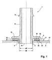
- a nozzle 1 is shown having a tubular body member 11 with an annular body member 12.
- the fuel tank attachment (see. Fig. 6 and 7 ) is therefore designed here as a nozzle.
- the first component is the tubular body element 11 with the annular body element 12.
- annular flange body 3 is arranged with a thickness D, which is the second structural element (see component 35 of FIG Fig. 6 and 7 ).
- the flange body 3 is located above an opening 5 of the container 4.
- the annular body member 12 of the tubular body member 11 has a distance a to the tube outlet opening 18 in the region of the opening 5, which is greater than the thickness D of the flange.
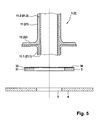
- an outer diameter dR of the tubular body member 11 is about as large as an inner diameter dB of the opening but smaller than an inner diameter dF of the flange body 3 (see also FIG Fig. 3 ).
- connection unit with a circumferential retaining rib thirteenth
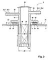
- Valve element 2 shown has a tubular body element 21 with an annular body element 22.
- the fuel tank attachment (see. Fig. 6 and 7 ) is thus formed here as a valve element 2.
- the first component is the tubular body element 21 with the annular body element 22.
- the flange body 3 is the second structural element (see the component 35 of FIG Fig. 6 and 7 ).
- the flange body is located above the opening 5 of the container 4.
- the annular body member 22 of the tubular body member 21 has in the region of the opening 5 also at a distance a to its end, which is substantially greater than the thickness D of the flange 3.
- the tubular body member 21 protrudes far into the opening 5 of the container 4.
- tube outlet openings 28 are arranged.
- the outer diameter dR of the tubular body member 21 is approximately as large as the inner diameter dB of the opening but smaller than the inner diameter dF of the flange body 3 (see also FIG Fig. 3 ).
- tubular body member 21 The opposite end of the tubular body member 21 is closed with a lid member 24.
- connecting pipe elements 25 and 26 with at least one circumferential retaining rib 23.1, 23.2, 23.3, 23.4 are arranged on the tubular body element 21.
- valve element 27 is arranged.
- first component and the outer wall 41 of the container 4 consist of non-compatible thermoplastics
- a second component is used as a connection adapter for connecting the first component to the outer wall 41.
- the connection adapter takes on the function of entering on the one hand a fluid-tight connection with the first component and on the other side just such with the container 4.
- the nozzle 1 according to Fig. 1 and the valve unit 2 according to Fig. 2 are in the range tubular body member 11, 21, ring body member 12, 22 (first component) and annular flange 3 (second component) formed similarly.
- the ring body element is thereby nose-shaped out of the tubular body element.
- the underside surface element of the annular body element is essentially planar.
- the outer transitions are rounded, while the inner wall passes smoothly.
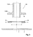
- Parts 1 and 3 are in the Fig. 3 to 5 shown in various embodiments.
- Tubular body element 11, 21 and annular body element 12, 22 are made of polyamide, in the following PA.
- the outer layer, ie the outer wall 41, of the multilayer container 4 is, as already mentioned, made of polyethylene, in the following PE.
- the flange body 3, i. the second component consists of a mixture of PE and PA with a grafted PEgPA copolymer as compatibilizer, and is designed as a copolymer flange body 31.
- the mixture may include additives such as stabilizers, lubricants, metallic pigments and the like.
- a surface element of the flange body 3, ie its joining surface 36, is then pretreated. This can be done, for example, by a plasma treatment or a plasma coating, through which a layer 33 is applied.
- the thickness of the layer can be about 0.001 ⁇ m to 100 ⁇ m.
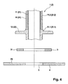
- a second embodiment shows Fig. 4 , Tubular body element 11, 21 and annular body element 12, 22 consist of a cup-shaped PA partial body 11.1, 21.1, ie the first structural element around which a partial body 11.2, 21.2 is formed above the annular body element.
- the part body 11.2, 21.2 is the second component made of the mixture of PE and PA with a grafted PEgPA copolymer as a compatibilizer.
- the part body 11.2, 21.2 is connected to the tubular body member 11, 21 cohesively.
- the outer layer i. the outer wall of the multilayer container 4 is also made of PE here.
- the flange body 3 is a further second component, which is designed as a copolymer flange body 31. It consists of the mixture of PE and PA with a grafted PEgPA copolymer as a compatibilizer and optionally additives such as stabilizers, lubricants, metallic pigments and the like.
- Tubular body element 11, 21 and annular body element 12, 22 consist of a part body 11.2, 21.2, ie the second component, in the form of a core body, at least on the fuel vapors or the fuel exposed surfaces with PA - part bodies 11.1, 21.1, ie the first components , coated, ie materially connected, is.
- the outer layer, ie the outer wall 41, of the multilayer container 4 is made of PE.
- the flange body 3, which is a further second component, is designed as a copolymer flange body 31.
- the pipe body member 11, 21 is molded from PA with the annular flange body member 12, 21 (first member).
- the tubular body member 11 terminates in the circumferential retaining rib 13.
- the opposite end 28 is just long enough from the lower edge of the flange body member that it can extend into the container 4 in this short over the inner wall of the container.
- the tubular body member 21 is closed with the lid member 24.
- connecting pipe elements 25, 26 with retaining ribs 23.1,..., 23.4 are integrally formed on the tubular body element 21.
- the lid member 24 opposite end of the tubular body member 21 is so long that it protrude far into the container and can accommodate the valve member 27 in its interior. So that the gases can flow freely into the valve element, tube outlet openings 28 are formed.
- the flange body 3 (second component) is subsequently formed from the mixture of PE and PA with a grafted PEgPA copolymer as compatibilizer.
- the first and second components are molded by injection molding.
- the joining surface 36 is then plasma treated, thus forming the layer 33.
- the plasma is a mixture of positive and negative charge carriers in relatively high density, neutral particles and photons.
- the densities of the positive ions and the electrons are so great that the charges compensate each other over time.
- the plasma is to be understood as a separate state of matter.
- the plasma generation is in a gas atmosphere, for.
- air and its components or a noble gas atmosphere for.
- a noble gas atmosphere for.
- helium, neon, argon, krypton, xenon, radon and their compounds ignited a discharge.
- the ions are extracted from the plasma from the carrier, i. H. the joining surface 36 as a target, d. H.
- Layer material extracted which is thereby atomized.
- ions are generated in the ion source and accelerated to a short distance and directed as a beam onto the surface element 36.
- the layer 33 grows under open conditions.
- the layer 33 is applied in the already mentioned thickness range of about 0.001 ⁇ m to 100 ⁇ m.
- first and second components are welded together.
- the production is carried out by means of two-component injection molding.
- both nozzle 1 and tank vent valve 2 are prepared for attachment to the container 4 and are shipped to final assembly.
- the nozzle 1 and the tank vent valve 2 are welded to the intended opening 4 for them on the container made of PE.
- the nozzle 1 and the tank vent valve 2 are connected by their design and plastics liquid-tight with the container 4.
- volume expansion indices PE ⁇ PE / PA ⁇ PA are chosen so that the cohesive connections a possible swelling safely withstand, since a swelling - albeit to a lesser extent - can also be done with fuel-resistant plastic.
Landscapes
- Engineering & Computer Science (AREA)
- Mechanical Engineering (AREA)
- General Engineering & Computer Science (AREA)
- Chemical & Material Sciences (AREA)
- Manufacturing & Machinery (AREA)
- Plasma & Fusion (AREA)
- Physics & Mathematics (AREA)
- Health & Medical Sciences (AREA)
- Organic Chemistry (AREA)
- Polymers & Plastics (AREA)
- Medicinal Chemistry (AREA)
- Chemical Kinetics & Catalysis (AREA)
- Materials Engineering (AREA)
- Cooling, Air Intake And Gas Exhaust, And Fuel Tank Arrangements In Propulsion Units (AREA)
- Laminated Bodies (AREA)
- Details Of Rigid Or Semi-Rigid Containers (AREA)
Claims (15)
- Composant pour réservoir de carburant,
présentant une première partie (12; 11, 12, 21, 22; 11.1: 21.1) constituée d'une première matière synthétique (A) et une deuxième partie (35; 3; 11.2; 21.2),
la deuxième partie étant constituée d'un mélange de la première matière synthétique et d'une deuxième matière synthétique (B),
la première et la deuxième matière synthétique n'étant pas miscibles l'une dans l'autre,
le mélange contenant un agent de compatibilisation qui permet de mélanger la première et la deuxième matière synthétique,
la première et la deuxième partie étant reliées l'une à l'autre en correspondance de matière,
la première matière synthétique étant une matière synthétique qui résiste au carburant et la deuxième matière synthétique étant une matière synthétique qui ne résiste pas au carburant,
l'agent de compatibilisation étant un copolymère de la première et de la deuxième matière synthétique,
la première matière synthétique étant un polyamide (PA) et la deuxième matière synthétique un polyéthylène (PE),
la deuxième partie étant reliée à la première partie par une première surface de jonction,
la deuxième partie étant configurée pour pouvoir être reliée en correspondance de matière avec une troisième partie (43) par une deuxième surface de jonction,
la troisième partie étant située sur la paroi extérieure (41) d'un réservoir (4) à carburant,
la troisième partie présentant la deuxième matière synthétique et la teneur du copolymère (AB) dans le mélange étant d'au plus 15 % en poids. - Composant pour réservoir de carburant selon la revendication 1, dans lequel le copolymère est un copolymère greffé.
- Composant pour réservoir de carburant selon la revendication 1 ou 2, dans lequel le copolymère présente un agent supplémentaire de compatibilisation.
- Composant pour réservoir de carburant selon l'une des revendications précédentes, dans lequel la teneur de la première matière synthétique dans le mélange est inférieure à la teneur de la deuxième matière synthétique.
- Composant pour réservoir de carburant selon la revendication 4, dans lequel la teneur de la première matière synthétique est d'au plus 35 % en poids et est en particulier comprise entre 20 % en poids et 30 % en poids.
- Réservoir à carburant, en particulier réservoir (4) à carburant pour véhicule automobile, présentant au moins un composant (1; 2) pour réservoir à carburant selon l'une des revendications précédentes.
- Procédé de fabrication d'un composant pour réservoir à carburant, le procédé présentant les étapes suivantes :- préparation d'un premier composant (12; 11, 12; 21, 22; 11.1; 21.1) en une première matière synthétique (A), la première matière synthétique résistant au carburant,- préparation d'un deuxième composant (35; 3, 11.2; 21.2) en un mélange de la première matière synthétique avec une deuxième matière synthétique, le mélange contenant un agent de compatibilisation qui rend miscibles la première et la deuxième matière synthétique, la deuxième matière synthétique ne résistant pas au carburant et- liaison en correspondance de matière du premier composant au deuxième composant,
l'agent de compatibilisation étant un copolymère de la première et de la deuxième matière synthétique,
la liaison en correspondance de matière entre le premier composant et le deuxième composant s'effectuant par soudage,
la première matière synthétique étant un polyamide (PA) et la deuxième matière synthétique un polyéthylène (PE),
la teneur du copolymère (AB) dans le mélange étant d'au plus 15 % en poids. - Procédé selon la revendication 7, dans lequel le copolymère est un copolymère greffé.
- Procédé selon la revendication 8, dans lequel pour préparer le copolymère greffé, on greffe la deuxième matière synthétique pour ensuite former des liaisons covalentes avec la première matière synthétique.
- Procédé selon l'une des revendications 7 à 9 qui précèdent, dans lequel une surface de jonction (36; 42) du deuxième composant subit un prétraitement avant la liaison en correspondance de matière.
- Procédé selon la revendication 10, dans lequel le prétraitement recourt à une ou plusieurs des dispositions suivantes :- traitement au plasma,- enduction au plasma,- traitement à la flamme,- gravure chimique,- prétraitement mécanique, en particulier formation d'une rugosité.
- Procédé selon l'une des revendications 7 à 11, dans lequel le composant de réservoir à carburant est fabriqué en utilisant un procédé de moulage par injection de matière synthétique à un ou plusieurs composants, le deuxième composant étant fabriqué d'abord en injectant le mélange dans un moule, le deuxième composant étant ensuite fabriqué et relié en correspondance de matière au premier composant en injectant la première matière synthétique dans le moule.
- Procédé selon la revendication 12, dans lequel une surface de fonction (36) du deuxième composant subit un prétraitement avant l'injection de la première matière synthétique.
- Procédé selon l'une des revendications 7 à 13 qui précèdent, dans lequel pour préparer le copolymère, on utilise un agent supplémentaire de compatibilisation qui est ajouté sous forme solide ou liquide au mélange de la première et de la deuxième matière synthétique, cet agent de compatibilisation étant au moins en partie consommé lors de la copolymérisation.
- Procédé selon la revendication 14, dans lequel l'agent supplémentaire de compatibilisation contient des groupes isocyanate et/ou des oligomères qui présentent des groupes époxy et/ou des groupes anhydride d'acide maléique ou des groupes oxazoline.
Applications Claiming Priority (2)
| Application Number | Priority Date | Filing Date | Title |
|---|---|---|---|
| DE102007013472A DE102007013472B4 (de) | 2007-03-21 | 2007-03-21 | Bauteil |
| PCT/EP2008/053288 WO2008113821A1 (fr) | 2007-03-21 | 2008-03-19 | Composant rapporté pour réservoir de carburant et procédé de fabrication d'un composant rapporté pour réservoir de carburant |
Publications (2)
| Publication Number | Publication Date |
|---|---|
| EP2129708A1 EP2129708A1 (fr) | 2009-12-09 |
| EP2129708B1 true EP2129708B1 (fr) | 2011-02-16 |
Family
ID=55701624
Family Applications (1)
| Application Number | Title | Priority Date | Filing Date |
|---|---|---|---|
| EP08718013A Not-in-force EP2129708B1 (fr) | 2007-03-21 | 2008-03-19 | Composant rapporté pour réservoir de carburant et procédé de fabrication d'un composant rapporté pour réservoir de carburant |
Country Status (5)
| Country | Link |
|---|---|
| US (1) | US20110056966A1 (fr) |
| EP (1) | EP2129708B1 (fr) |
| AT (1) | ATE498649T1 (fr) |
| DE (1) | DE502008002611D1 (fr) |
| WO (1) | WO2008113821A1 (fr) |
Families Citing this family (5)
| Publication number | Priority date | Publication date | Assignee | Title |
|---|---|---|---|---|
| FR2945981B1 (fr) * | 2009-05-27 | 2012-06-22 | Mann & Hummel Gmbh | Procede d'assemblage d'un element en polypropylene et d'un element en polyamide. |
| DE102009058360A1 (de) | 2009-12-15 | 2011-06-16 | Reinhard Feichtinger | Kraftstoffleitung |
| DE202009016927U1 (de) * | 2009-12-15 | 2010-06-02 | Feichtinger, Reinhard | Kraftstoffanbauteil |
| EP3156212A1 (fr) * | 2015-10-16 | 2017-04-19 | Henkel AG & Co. KGaA | Procede de soudage d'une matiere plastique a base de polyolefine avec une matiere plastique a base d'un polymere contenant un groupe de carbonyle |
| ES2703179T3 (es) | 2015-10-16 | 2019-03-07 | Henkel Ag & Co Kgaa | Procedimiento para soldar los plásticos poliamida y poli(met)acrilato |
Family Cites Families (57)
| Publication number | Priority date | Publication date | Assignee | Title |
|---|---|---|---|---|
| US3880953A (en) * | 1969-03-17 | 1975-04-29 | Goodyear Tire & Rubber | Adhesive composition |
| US4123582A (en) * | 1973-06-13 | 1978-10-31 | Goodyear Aerospace Corporation | Building form for molded articles having a urethane coating |
| US4611031A (en) * | 1985-01-28 | 1986-09-09 | Rohm And Haas Company | Process for the preparation of a compatibilizer for concentrated polymer blends and compatibilizer product |
| US5129544A (en) * | 1990-11-08 | 1992-07-14 | Jacobson Wendell L | Laminated fuel tank structure |
| JP3094513B2 (ja) * | 1991-06-12 | 2000-10-03 | 三菱化学株式会社 | 多層容器 |
| DE69419998T2 (de) * | 1993-10-12 | 1999-12-02 | Elf Atochem S.A., Puteaux | Gegenstand aus Polyamid/Polyolefin-Mischung mit Verbindungsnaht |
| US5928745A (en) * | 1994-06-23 | 1999-07-27 | Cellresin Technologies, Llc | Thermoplastic fuel tank having reduced fuel vapor emissions |
| TW369499B (en) * | 1995-05-12 | 1999-09-11 | Sumitomo Chemical Co | Formed hollow container and process |
| CA2175609C (fr) * | 1995-05-12 | 2004-06-22 | Hata, Nobuhiko | Reservoir d'essence |
| DE19535413C1 (de) | 1995-09-23 | 1996-10-02 | Rasmussen Gmbh | Rohrartiger Stutzen |
| AU7309096A (en) * | 1995-10-27 | 1997-05-15 | Elf Atochem S.A. | Mixture of polyolefin and polyamide alloy, and fabrication process |
| DE29805999U1 (de) * | 1998-04-03 | 1998-06-25 | Agrodyn Hochspannungstechnik GmbH, 33803 Steinhagen | Vorrichtung zur Plasmabehandlung von Oberflächen |
| US6300417B1 (en) * | 1998-12-22 | 2001-10-09 | The Texas A&M University System | Method for improving the impact resistance and scratch resistance of polymeric systems |
| WO2000037517A1 (fr) * | 1998-12-22 | 2000-06-29 | Denki Kagaku Kogyo Kabushiki Kaisha | Copolymere olefine/styrene/diene reticule, procede de production dudit copolymere et ses utilisations |
| US6398059B1 (en) * | 1999-03-04 | 2002-06-04 | Kuraray Co., Ltd. | Fuel container |
| US6218024B1 (en) * | 1999-06-04 | 2001-04-17 | Macro Engineering & Technology Inc. | Multilayer plastic film |
| CA2314480C (fr) * | 1999-07-29 | 2007-01-02 | Kuraray Co., Ltd. | Conteneur a carburant |
| BE1012907A3 (fr) * | 1999-09-22 | 2001-05-08 | Solvay | Systeme et procede d'obturation d'une ouverture d'un reservoir. |
| DE19946530B4 (de) * | 1999-09-28 | 2007-01-25 | Ti Automotive Technology Center Gmbh | Doppelwandiger Kraftstoffbehälter |
| US20010045433A1 (en) * | 1999-12-18 | 2001-11-29 | Ellis Thomas S. | Permeation barrier fuel tank |
| US6395357B1 (en) * | 1999-12-18 | 2002-05-28 | Delphi Technologies, Inc. | Fuel permeation barrier fuel tank |
| ATE271983T1 (de) * | 2000-02-07 | 2004-08-15 | Ti Automotive Technology Ct Gm | Mehrschichtkraftstoffbehälter |
| US6379791B1 (en) * | 2000-02-08 | 2002-04-30 | 3M Innovative Properties Company | Compatibilized pressure-sensitive adhesives |
| DE10008725A1 (de) * | 2000-02-24 | 2001-08-30 | Basell Polyolefine Gmbh | Kunststoffhohlkörper mit erhöhter Brandfestigkeit durch Flammschutzmittel |
| DE10062997A1 (de) | 2000-12-16 | 2002-07-18 | Rasmussen Gmbh | Rohrartiger Stutzen |
| US20030198768A1 (en) * | 2001-02-13 | 2003-10-23 | Ti Automotive Technology Center Gmbh | Fuel tank having a multilayer structure |
| US6884482B2 (en) * | 2001-03-27 | 2005-04-26 | Kuraray Co., Ltd. | Fuel container having excellent gasoline barrier properties |
| US6887581B2 (en) * | 2001-04-27 | 2005-05-03 | Toyo Boseki Kabushiki Kaisha | Laminate for automobile parts |
| US20030044553A1 (en) * | 2001-08-23 | 2003-03-06 | Ravi Ramanathan | Fuel tanks |
| FR2831113B1 (fr) * | 2001-10-24 | 2004-01-02 | Inergy Automotive Systems Man | Systeme et procede d'obturation d'une ouverture d'un reservoir |
| DE10164408A1 (de) * | 2001-12-28 | 2003-07-17 | Degussa | Flüssigkeits- oder dampfführendes System mit einer Fügezone aus einem coextrudierten Mehrschichtverbund |
| US6722521B2 (en) * | 2002-05-07 | 2004-04-20 | Visteon Global Technologies, Inc. | Low permeation pinchoff connection for bridging a barrier layer and method of making same |
| DE10223865B4 (de) | 2002-05-29 | 2007-08-16 | Plasmatreat Gmbh | Verfahren zur Plasmabeschichtung von Werkstücken |
| US7211307B2 (en) * | 2002-07-11 | 2007-05-01 | Visteon Global Techologies, Inc. | Low permeation polymer fuel tank |
| BR0315039A (pt) * | 2002-10-07 | 2005-08-16 | Polyone Corp | Composto vulcanizado termoplástico e método de uso de microscopia por força atÈmica para determinar a morfologia de misturas compatibilizadas de vulcanizados termoplásticos e para prever as propriedades fìsicas a partir da mesma |
| JP4175942B2 (ja) * | 2002-10-29 | 2008-11-05 | 株式会社クラレ | 積層構造体 |
| US20040092409A1 (en) * | 2002-11-11 | 2004-05-13 | Liesen Gregory Peter | Alkyl (meth) acrylate copolymers |
| EP1574330A1 (fr) * | 2002-12-17 | 2005-09-14 | Ube Industries, Ltd. | Structure laminee dotee d'une excellente caracteristique permettant d'empecher l'infiltration de carburants |
| US7862872B2 (en) * | 2003-03-21 | 2011-01-04 | Arkema France | Multilayer structure based on polyamides and graft copolymers having polyamide blocks |
| BE1015547A3 (fr) * | 2003-06-02 | 2005-06-07 | Inergy Automotive Systems Res | Reservoir a carburant en matiere plastique multicouche et procede pour fabriquer un tel reservoir. |
| JP4596787B2 (ja) * | 2003-04-25 | 2010-12-15 | 豊田合成株式会社 | 燃料タンク |
| US7648771B2 (en) * | 2003-12-31 | 2010-01-19 | Kimberly-Clark Worldwide, Inc. | Thermal stabilization and processing behavior of block copolymer compositions by blending, applications thereof, and methods of making same |
| FR2867255B1 (fr) * | 2004-03-04 | 2007-11-30 | Inergy Automotive Systems Res | Systeme de fixation de deux composants, procede de fixation au moyen de ce systeme de fixation et systeme a carburant |
| US8381928B2 (en) * | 2004-06-04 | 2013-02-26 | Ti Group Automotive Systems, L.L.C. | Multilayer fuel tank with a seam having an overlay for reducing vapor permeation |
| JP2006151365A (ja) * | 2004-10-26 | 2006-06-15 | Tokai Rubber Ind Ltd | 樹脂製燃料タンク用接合部品およびその製法 |
| US7771805B1 (en) * | 2005-06-01 | 2010-08-10 | Ovation Polymer Technology And Engineered Materials, Inc. | Low organic vapor permeation resin composition |
| US8062725B2 (en) * | 2005-06-01 | 2011-11-22 | Ovetion Polymer Technology and Engineered Materials, Inc. | Low organic vapor permeation resin |
| EP1910057B1 (fr) * | 2005-06-28 | 2018-01-24 | Plastic Omnium Advanced Innovation and Research | Procédé de fabrication de réservoir à carburant pourvu d'accessoires internes |
| KR20070028173A (ko) * | 2005-09-07 | 2007-03-12 | 주식회사 엘지화학 | 탱크 개구부 밀봉 시스템 및 밀봉 방법 |
| JP4460513B2 (ja) * | 2005-09-21 | 2010-05-12 | 八千代工業株式会社 | バリア材層を有する容器の構造 |
| US7700692B2 (en) * | 2006-04-28 | 2010-04-20 | E.I. Du Pont De Nemours And Company | Process for recycling polyolefin blend composition using an ethylene copolymer compatibilizing agent |
| US7810666B2 (en) * | 2006-07-07 | 2010-10-12 | Kautex Textron Gmbh & Co. Kg | Fuel tank seam with lead-through means |
| JP2008143350A (ja) * | 2006-12-08 | 2008-06-26 | Tokai Rubber Ind Ltd | 溶着ジョイントの溶着取付構造及び燃料タンク |
| KR100931151B1 (ko) * | 2007-12-13 | 2009-12-10 | 현대자동차주식회사 | 폴리아미드 수지 조성물 |
| CN101367466B (zh) * | 2008-08-15 | 2011-11-23 | 李束为 | 储存运输油品装置 |
| KR20110012430A (ko) * | 2009-07-30 | 2011-02-09 | 현대자동차주식회사 | 폴리아미드 수지 점토 복합체 조성물 및 이를 이용하여 제조된 연료 수송 튜브 |
| DE202009016927U1 (de) * | 2009-12-15 | 2010-06-02 | Feichtinger, Reinhard | Kraftstoffanbauteil |
-
2008
- 2008-03-19 WO PCT/EP2008/053288 patent/WO2008113821A1/fr not_active Ceased
- 2008-03-19 AT AT08718013T patent/ATE498649T1/de active
- 2008-03-19 EP EP08718013A patent/EP2129708B1/fr not_active Not-in-force
- 2008-03-19 US US12/530,967 patent/US20110056966A1/en not_active Abandoned
- 2008-03-19 DE DE502008002611T patent/DE502008002611D1/de active Active
Also Published As
| Publication number | Publication date |
|---|---|
| US20110056966A1 (en) | 2011-03-10 |
| WO2008113821A1 (fr) | 2008-09-25 |
| EP2129708A1 (fr) | 2009-12-09 |
| ATE498649T1 (de) | 2011-03-15 |
| DE502008002611D1 (de) | 2011-03-31 |
Similar Documents
| Publication | Publication Date | Title |
|---|---|---|
| EP2512857B1 (fr) | Elément à rapporter sur un réservoir de carburant et procédé de fabrication associé | |
| DE10192212B4 (de) | Durchdringungs- und auslauffeste Konstruktion für Kraftstofftank-Anbaugeräte | |
| EP1396326B1 (fr) | Connecteur entre un conduit de fluide et l'orifice d'un récipient | |
| EP2030755B1 (fr) | Procédé de fabrication d'un manchon | |
| DE19953746C2 (de) | Verfahren zur Herstellung eines Stutzens | |
| EP2129708B1 (fr) | Composant rapporté pour réservoir de carburant et procédé de fabrication d'un composant rapporté pour réservoir de carburant | |
| DE102012010608B4 (de) | Anzünder und Verfahren zur Herstellung eines Anzünders für einen Gasgenerator | |
| DE102014001967B4 (de) | Betankungsvorrichtung und Verfahren zur Herstellung einer Betankungsvorrichtung | |
| WO2019042902A1 (fr) | Réservoir de liquide pour un véhicule automobile et procédé de fabrication d'un réservoir de liquide | |
| EP1559537B1 (fr) | Tuyau multicouche en plastique à propriété barrière | |
| DE19946530B4 (de) | Doppelwandiger Kraftstoffbehälter | |
| DE60124038T2 (de) | Kunststoffkraftstofftank mit Anordnung zum kraftstoffdichten Anschweissen einer Komponente | |
| DE60208812T2 (de) | Kraftstofftank und verfahren zur seiner herstellung | |
| DE60224551T2 (de) | Vorrichtung und verfahren zum verschliessen einer tanköffnung | |
| DE19705440C2 (de) | Roll-over-Ventil | |
| DE10018310B4 (de) | Kraftstoffbehälter aus Kunststoff und Verfahren zu dessen Herstellung | |
| EP3676080A1 (fr) | Réservoir de liquide et procédé de fabrication d'un réservoir de liquide | |
| DE69807387T2 (de) | Einfüllvorrichtung für einen Kraftstofftank eines Kraftfahrzeuges mit verstärkter Rahmeneinlage im Tankverschlussdeckel | |
| EP1482233A2 (fr) | Embout tubulaire | |
| WO2011073146A1 (fr) | Conduite de carburant et système de réservoir de carburant | |
| DE10062997A1 (de) | Rohrartiger Stutzen | |
| DE102007026805B4 (de) | Mediendichtes Bauteil, insbesondere Entlüftungsrohr, umfassend mindestens ein Metallteil und mindestens ein Kunststoffteil | |
| DE102007013472B4 (de) | Bauteil | |
| DE102020111015A1 (de) | Fahrzeugtank und Verfahren zur Herstellung eines Fahrzeugtanks | |
| DE60205386T2 (de) | Schweissstruktur für ein Kunststoffteil |
Legal Events
| Date | Code | Title | Description |
|---|---|---|---|
| PUAI | Public reference made under article 153(3) epc to a published international application that has entered the european phase |
Free format text: ORIGINAL CODE: 0009012 |
|
| 17P | Request for examination filed |
Effective date: 20091021 |
|
| AK | Designated contracting states |
Kind code of ref document: A1 Designated state(s): AT BE BG CH CY CZ DE DK EE ES FI FR GB GR HR HU IE IS IT LI LT LU LV MC MT NL NO PL PT RO SE SI SK TR |
|
| RIN1 | Information on inventor provided before grant (corrected) |
Inventor name: AMESOEDER, SIMON Inventor name: FEICHTINGER, REINHARD |
|
| DAX | Request for extension of the european patent (deleted) | ||
| GRAP | Despatch of communication of intention to grant a patent |
Free format text: ORIGINAL CODE: EPIDOSNIGR1 |
|
| GRAS | Grant fee paid |
Free format text: ORIGINAL CODE: EPIDOSNIGR3 |
|
| GRAA | (expected) grant |
Free format text: ORIGINAL CODE: 0009210 |
|
| AK | Designated contracting states |
Kind code of ref document: B1 Designated state(s): AT BE BG CH CY CZ DE DK EE ES FI FR GB GR HR HU IE IS IT LI LT LU LV MC MT NL NO PL PT RO SE SI SK TR |
|
| REG | Reference to a national code |
Ref country code: GB Ref legal event code: FG4D Free format text: NOT ENGLISH |
|
| REG | Reference to a national code |
Ref country code: CH Ref legal event code: EP |
|
| REG | Reference to a national code |
Ref country code: IE Ref legal event code: FG4D Free format text: LANGUAGE OF EP DOCUMENT: GERMAN |
|
| REF | Corresponds to: |
Ref document number: 502008002611 Country of ref document: DE Date of ref document: 20110331 Kind code of ref document: P |
|
| REG | Reference to a national code |
Ref country code: DE Ref legal event code: R096 Ref document number: 502008002611 Country of ref document: DE Effective date: 20110331 |
|
| REG | Reference to a national code |
Ref country code: NL Ref legal event code: VDEP Effective date: 20110216 |
|
| LTIE | Lt: invalidation of european patent or patent extension |
Effective date: 20110216 |
|
| PG25 | Lapsed in a contracting state [announced via postgrant information from national office to epo] |
Ref country code: LT Free format text: LAPSE BECAUSE OF FAILURE TO SUBMIT A TRANSLATION OF THE DESCRIPTION OR TO PAY THE FEE WITHIN THE PRESCRIBED TIME-LIMIT Effective date: 20110216 Ref country code: ES Free format text: LAPSE BECAUSE OF FAILURE TO SUBMIT A TRANSLATION OF THE DESCRIPTION OR TO PAY THE FEE WITHIN THE PRESCRIBED TIME-LIMIT Effective date: 20110527 Ref country code: HR Free format text: LAPSE BECAUSE OF FAILURE TO SUBMIT A TRANSLATION OF THE DESCRIPTION OR TO PAY THE FEE WITHIN THE PRESCRIBED TIME-LIMIT Effective date: 20110216 Ref country code: SE Free format text: LAPSE BECAUSE OF FAILURE TO SUBMIT A TRANSLATION OF THE DESCRIPTION OR TO PAY THE FEE WITHIN THE PRESCRIBED TIME-LIMIT Effective date: 20110216 Ref country code: LV Free format text: LAPSE BECAUSE OF FAILURE TO SUBMIT A TRANSLATION OF THE DESCRIPTION OR TO PAY THE FEE WITHIN THE PRESCRIBED TIME-LIMIT Effective date: 20110216 Ref country code: GR Free format text: LAPSE BECAUSE OF FAILURE TO SUBMIT A TRANSLATION OF THE DESCRIPTION OR TO PAY THE FEE WITHIN THE PRESCRIBED TIME-LIMIT Effective date: 20110517 Ref country code: NO Free format text: LAPSE BECAUSE OF FAILURE TO SUBMIT A TRANSLATION OF THE DESCRIPTION OR TO PAY THE FEE WITHIN THE PRESCRIBED TIME-LIMIT Effective date: 20110516 Ref country code: PT Free format text: LAPSE BECAUSE OF FAILURE TO SUBMIT A TRANSLATION OF THE DESCRIPTION OR TO PAY THE FEE WITHIN THE PRESCRIBED TIME-LIMIT Effective date: 20110616 |
|
| PG25 | Lapsed in a contracting state [announced via postgrant information from national office to epo] |
Ref country code: NL Free format text: LAPSE BECAUSE OF FAILURE TO SUBMIT A TRANSLATION OF THE DESCRIPTION OR TO PAY THE FEE WITHIN THE PRESCRIBED TIME-LIMIT Effective date: 20110216 Ref country code: SI Free format text: LAPSE BECAUSE OF FAILURE TO SUBMIT A TRANSLATION OF THE DESCRIPTION OR TO PAY THE FEE WITHIN THE PRESCRIBED TIME-LIMIT Effective date: 20110216 Ref country code: CY Free format text: LAPSE BECAUSE OF FAILURE TO SUBMIT A TRANSLATION OF THE DESCRIPTION OR TO PAY THE FEE WITHIN THE PRESCRIBED TIME-LIMIT Effective date: 20110216 Ref country code: FI Free format text: LAPSE BECAUSE OF FAILURE TO SUBMIT A TRANSLATION OF THE DESCRIPTION OR TO PAY THE FEE WITHIN THE PRESCRIBED TIME-LIMIT Effective date: 20110216 Ref country code: PL Free format text: LAPSE BECAUSE OF FAILURE TO SUBMIT A TRANSLATION OF THE DESCRIPTION OR TO PAY THE FEE WITHIN THE PRESCRIBED TIME-LIMIT Effective date: 20110216 Ref country code: BG Free format text: LAPSE BECAUSE OF FAILURE TO SUBMIT A TRANSLATION OF THE DESCRIPTION OR TO PAY THE FEE WITHIN THE PRESCRIBED TIME-LIMIT Effective date: 20110516 |
|
| REG | Reference to a national code |
Ref country code: IE Ref legal event code: FD4D |
|
| BERE | Be: lapsed |
Owner name: FEICHTINGER, REINHARD Effective date: 20110331 |
|
| PG25 | Lapsed in a contracting state [announced via postgrant information from national office to epo] |
Ref country code: IE Free format text: LAPSE BECAUSE OF FAILURE TO SUBMIT A TRANSLATION OF THE DESCRIPTION OR TO PAY THE FEE WITHIN THE PRESCRIBED TIME-LIMIT Effective date: 20110216 Ref country code: DK Free format text: LAPSE BECAUSE OF FAILURE TO SUBMIT A TRANSLATION OF THE DESCRIPTION OR TO PAY THE FEE WITHIN THE PRESCRIBED TIME-LIMIT Effective date: 20110216 Ref country code: MC Free format text: LAPSE BECAUSE OF NON-PAYMENT OF DUE FEES Effective date: 20110331 Ref country code: EE Free format text: LAPSE BECAUSE OF FAILURE TO SUBMIT A TRANSLATION OF THE DESCRIPTION OR TO PAY THE FEE WITHIN THE PRESCRIBED TIME-LIMIT Effective date: 20110216 |
|
| PG25 | Lapsed in a contracting state [announced via postgrant information from national office to epo] |
Ref country code: RO Free format text: LAPSE BECAUSE OF FAILURE TO SUBMIT A TRANSLATION OF THE DESCRIPTION OR TO PAY THE FEE WITHIN THE PRESCRIBED TIME-LIMIT Effective date: 20110216 Ref country code: CZ Free format text: LAPSE BECAUSE OF FAILURE TO SUBMIT A TRANSLATION OF THE DESCRIPTION OR TO PAY THE FEE WITHIN THE PRESCRIBED TIME-LIMIT Effective date: 20110216 Ref country code: SK Free format text: LAPSE BECAUSE OF FAILURE TO SUBMIT A TRANSLATION OF THE DESCRIPTION OR TO PAY THE FEE WITHIN THE PRESCRIBED TIME-LIMIT Effective date: 20110216 |
|
| PLBE | No opposition filed within time limit |
Free format text: ORIGINAL CODE: 0009261 |
|
| STAA | Information on the status of an ep patent application or granted ep patent |
Free format text: STATUS: NO OPPOSITION FILED WITHIN TIME LIMIT |
|
| PG25 | Lapsed in a contracting state [announced via postgrant information from national office to epo] |
Ref country code: BE Free format text: LAPSE BECAUSE OF NON-PAYMENT OF DUE FEES Effective date: 20110331 Ref country code: MT Free format text: LAPSE BECAUSE OF FAILURE TO SUBMIT A TRANSLATION OF THE DESCRIPTION OR TO PAY THE FEE WITHIN THE PRESCRIBED TIME-LIMIT Effective date: 20110216 |
|
| 26N | No opposition filed |
Effective date: 20111117 |
|
| REG | Reference to a national code |
Ref country code: DE Ref legal event code: R097 Ref document number: 502008002611 Country of ref document: DE Effective date: 20111117 |
|
| PG25 | Lapsed in a contracting state [announced via postgrant information from national office to epo] |
Ref country code: IT Free format text: LAPSE BECAUSE OF FAILURE TO SUBMIT A TRANSLATION OF THE DESCRIPTION OR TO PAY THE FEE WITHIN THE PRESCRIBED TIME-LIMIT Effective date: 20110216 |
|
| REG | Reference to a national code |
Ref country code: CH Ref legal event code: PL |
|
| PG25 | Lapsed in a contracting state [announced via postgrant information from national office to epo] |
Ref country code: LI Free format text: LAPSE BECAUSE OF NON-PAYMENT OF DUE FEES Effective date: 20120331 Ref country code: CH Free format text: LAPSE BECAUSE OF NON-PAYMENT OF DUE FEES Effective date: 20120331 |
|
| PG25 | Lapsed in a contracting state [announced via postgrant information from national office to epo] |
Ref country code: LU Free format text: LAPSE BECAUSE OF NON-PAYMENT OF DUE FEES Effective date: 20110319 |
|
| PG25 | Lapsed in a contracting state [announced via postgrant information from national office to epo] |
Ref country code: IS Free format text: LAPSE BECAUSE OF FAILURE TO SUBMIT A TRANSLATION OF THE DESCRIPTION OR TO PAY THE FEE WITHIN THE PRESCRIBED TIME-LIMIT Effective date: 20110216 |
|
| PG25 | Lapsed in a contracting state [announced via postgrant information from national office to epo] |
Ref country code: TR Free format text: LAPSE BECAUSE OF FAILURE TO SUBMIT A TRANSLATION OF THE DESCRIPTION OR TO PAY THE FEE WITHIN THE PRESCRIBED TIME-LIMIT Effective date: 20110216 |
|
| PG25 | Lapsed in a contracting state [announced via postgrant information from national office to epo] |
Ref country code: HU Free format text: LAPSE BECAUSE OF FAILURE TO SUBMIT A TRANSLATION OF THE DESCRIPTION OR TO PAY THE FEE WITHIN THE PRESCRIBED TIME-LIMIT Effective date: 20110216 |
|
| PGFP | Annual fee paid to national office [announced via postgrant information from national office to epo] |
Ref country code: FR Payment date: 20130917 Year of fee payment: 6 Ref country code: GB Payment date: 20130919 Year of fee payment: 6 |
|
| REG | Reference to a national code |
Ref country code: AT Ref legal event code: MM01 Ref document number: 498649 Country of ref document: AT Kind code of ref document: T Effective date: 20130319 |
|
| PG25 | Lapsed in a contracting state [announced via postgrant information from national office to epo] |
Ref country code: AT Free format text: LAPSE BECAUSE OF NON-PAYMENT OF DUE FEES Effective date: 20130319 |
|
| GBPC | Gb: european patent ceased through non-payment of renewal fee |
Effective date: 20140319 |
|
| REG | Reference to a national code |
Ref country code: FR Ref legal event code: ST Effective date: 20141128 |
|
| PG25 | Lapsed in a contracting state [announced via postgrant information from national office to epo] |
Ref country code: GB Free format text: LAPSE BECAUSE OF NON-PAYMENT OF DUE FEES Effective date: 20140319 Ref country code: FR Free format text: LAPSE BECAUSE OF NON-PAYMENT OF DUE FEES Effective date: 20140331 |
|
| PGFP | Annual fee paid to national office [announced via postgrant information from national office to epo] |
Ref country code: DE Payment date: 20150410 Year of fee payment: 8 |
|
| REG | Reference to a national code |
Ref country code: DE Ref legal event code: R119 Ref document number: 502008002611 Country of ref document: DE |
|
| PG25 | Lapsed in a contracting state [announced via postgrant information from national office to epo] |
Ref country code: DE Free format text: LAPSE BECAUSE OF NON-PAYMENT OF DUE FEES Effective date: 20161001 |